SteamOvap ISE30 User manual
STEAM EXCHANGE HUMIDIFIER
Installation and Operation Manual
Please read and save this manual
steamOvap technologies inc, 1490 Mazuree, Montreal, Qc, H4N 1H2, Canada
Tel.: 1-844-357-4477 • www.steamOvap.com
Rev.200701
ISE

I N T R O D U C T I O N
Introduction
Foreword
Thank you for purchasing ISE steamOvap Steam Exchange Humidifier.
If you have quesons or comments please contact us:
www.steamOvap.com
1-844-357-4477
Description
ISE steam exchange humidifier is a steam generator that uses
pressurized steam heat exchanger to produce pure and sterile
steam at atmospheric pressure that is distributed in air
handling unit or venlaon duct, or directly into space.
ISE humidifier can be supplied with tap or treated water such
as reverse osmosis water or deionized water without alteraon
or addional required opon.
When tap water is used, the scale will come off the heat-
exchanger by the natural contracon and expansion of its
coiled shape tube . Scale pieces then accumulate at the
boom of the cylinder without the risk of clogging the drain
outlet.
Regular maintenance consists in opening and removing the
cylinder and cleaning the accumulated scale off.
ISE unique & patent pending vercal heat-exchanger allows for
very easy regular maintenance that consists in opening and
removing boom part of the cylinder and cleaning the
accumulated scale off without the need of any tool or
consumable.
Main features
Very accurate +/-1% and constant steam producon whatever water condion.
Fully modulang humidifier.
Drain water automacally cooled down at 140°F [60°C].
Pre-heang funcon for quick reacon upon demand.
Steam producon reducon opon.
Permanent stainless steel cylinder with thermal insulaon.
Easy and quick regular maintenance with no tool required.
Log of events and alarms easy to export.
Modbus RTU remote communicaon
Oponal remote communicaon BACnet (RS485)
Three year warranty (when installaon is commissioned by steamOvap authorized
service representave)
3

I N T R O D U C T I O N
Intended use
ISE steam exchange humidifier is intended exclusively to produce steam from water at
atmospheric pressure for air humidificaon.
Operang condions are specified in this Installaon and Operaon Manual (IOM).
Operaon of this humidifier in the intended use scope requires that all direcons and
informaon contained in this IOM are observed.
Any other use or operaon outside the above design scope without wrien authorizaon
from steamOvap may lead to trouble and hazardous condions and will void warranty.
No alteraon or modificaon to the humidifier must be done without wrien authorizaon
from steamOvap.
Replacement of any defecve components must be done with original component and spare
parts from steamOvap representave.
Installation and Operation Manual Limitation
This IOM is intended for trained and qualified personnel and must be applied along with the
applicable local codes and regulaons.
Any work related to installaon or service for this humidifier must comply with local code and
regulaon regarding safety and prevenon of accidents.
End of life disposition
Ensure that ISE steam exchange humidifier is empty from water, if not proceed same way as
for a standard drain for service.
Disconnect ISE steam exchange humidifier from power supply, electrical control signal, water
main supply, Steam line, and drain. ISE steam exchange humidifier can then be removed from
the wall or stand.
ISE steam exchange humidifier is an electrical equipment and as such MUST not be disposed
of in domesc waste.
This humidifier should be returned to the closest steamOvap authorized representave for
proper dismantling, recycling and disposion of components according to local regulaons.
4

Table of content
Introduction................................................................................................3
Table of content.........................................................................................5
Safety warnings.........................................................................................6
Before to proceed to Installation................................................................7
ISE Overview.............................................................................................8
Installation overview................................................................................11
Installation – step 1 Positioning & Mounting............................................12
Installation – step 2 Water supply installation..........................................17
Installation – step 3 Drain installation......................................................19
Installation – step 4 Pressurized steam & condensate installation...........21
Installation – step 5 Steam line installation..............................................23
Installation – step 6 Power supply installation..........................................30
Installation – step 7 Actuated valve connection.......................................31
Installation – step 8 Control installation....................................................32
Verification before start-up.......................................................................34
Configuration & Operation.......................................................................36
Warranty..................................................................................................48
5

S A F E T Y
Safety warnings
General
Risk of electric shock.
Disconnect power supply before installaon or service.
For safety and warranty reasons, Installaon and service of this humidifier should be
carried out by trained and qualified personnel.
Any work related to installaon and service of this humidifier must comply with local code
and regulaons regarding safety and prevenon of accidents.
Electrical Warning
Risk of electric shock.
Disconnect power supply before installaon or service.
Power supply connecon must be done by a trained and qualified electrician.
Any work related to power supply installaon or service of this humidifier must comply
with local code and regulaon regarding safety and prevenon of accidents.
Water safety warning
Any work related to water supply, drain connecon as well as steam lines and condensate
returns lines installaon or service of such for this humidifier must comply with local code
and regulaon regarding safety and prevenon of accidents.
Water supply connecon must be done by a trained and qualified plumber.
Risk of malfuncon. Steam lines should not have any restricon or blockage that
may cause a burst of pressure in the steam line.
Others
Risk of flooding. In order to avoid any risk of flooding steamOvap recommends a Hi
limit humidity switch installed in the air duct downstream of the steam distribuon
ramp.
Risk of freezing. Plan an an-freeze system in case of installaon in a locaon that
would be exposed to outside condions and suscepble of freezing.
Risk of malfuncon. Do not block steam outlet(s).
6
section
0

I N T E N D E D U S E
Before to proceed to Installation
Please read this Installation and Operation manual before to proceed to the Installation
Receiving & Unpacking
1. Upon receipt verify that packaging is complete and not damaged.
In case of damage, and/or missing boxes advise immediately the carrier by wring a
note on the waybill.
2. Verify that model of the humidifier matches the purchase order and that all
accessories are included.
3. Any missing item should be reported as soon as possible to steamOvap or its
representave and within 5 business days aer receipt.
steamOvap will not assume any responsibility for missing item aer this delay.
4. Proceed carefully to unpacking, and check that the humidifier and its accessories are
not damaged. in case of damage please proceed as for point 3
Included in standard delivery of ISE steam exchange
humidifier
1. ISE steam exchange humidifier
2. Water supply hose
3. Collar(s) to secure steam hose on steam outlet of ISE
4. 1-1/4in flexible hose for easy connecon to the drain outlet
5. Actuated control valve for pressurized steam input
6. Strainer to be installed on pressurized steam inlet upstream the actuated control valve
7. Float & Thermostac condensate trap for condensate return fro heat exchanger.
8. This IOM
Depending on other accessories ordered
9. Steam ramp(s)
10. Steam hose
11. Condensate hose
12. RH% sensors for duct or room
13. HI Limit RH% switch
14. Air flow switch
15. Condensate temperature switch
7
section
1

O V E R V I E W
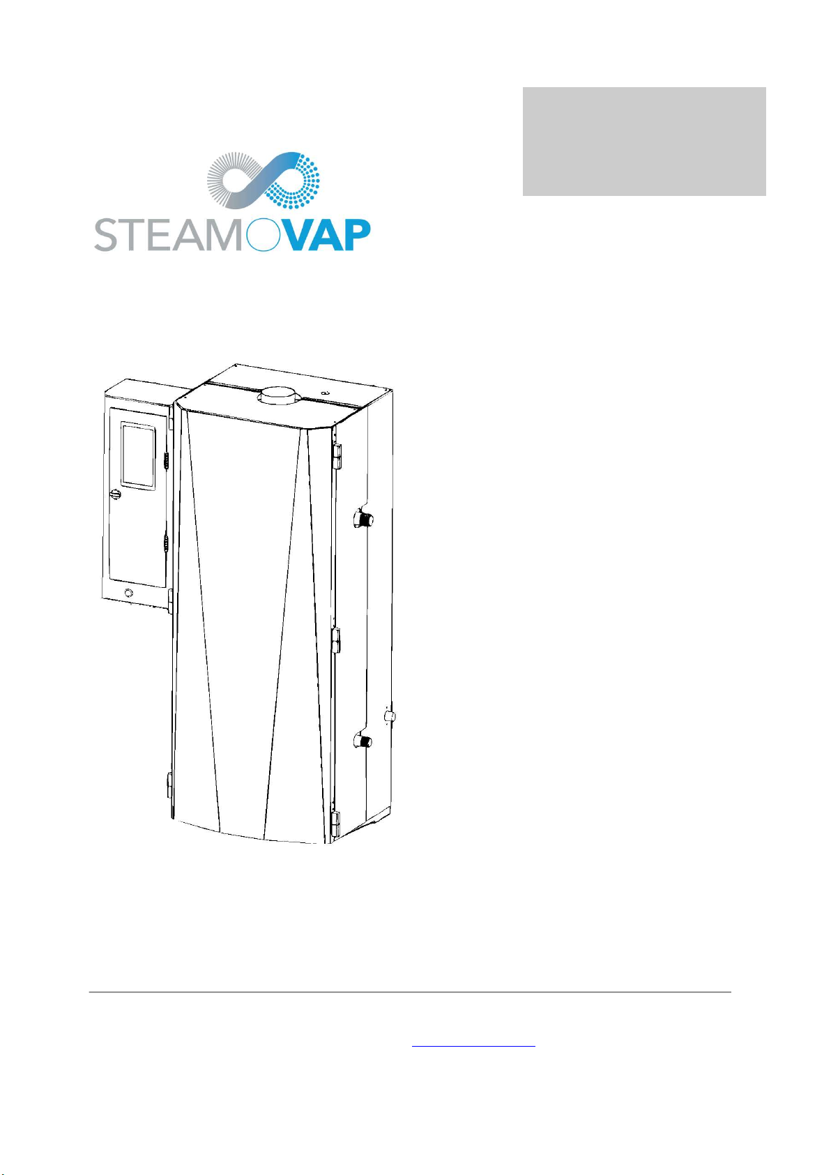
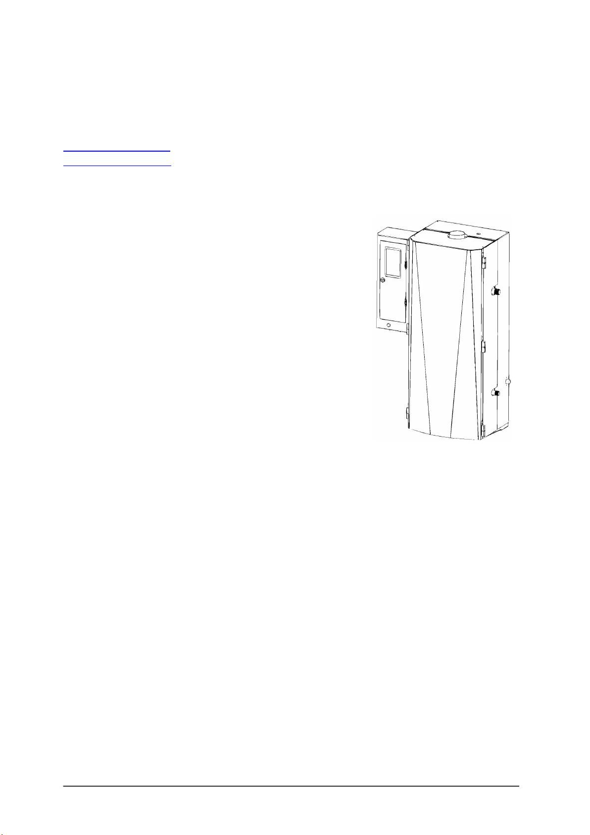
ISE Overview
ISE steam exchange humidifier
Figure 1 – ISE Overview
ISE product designation & name plate
Figure 2 –ISE Name plate
8
section
2
O V E R V I E W
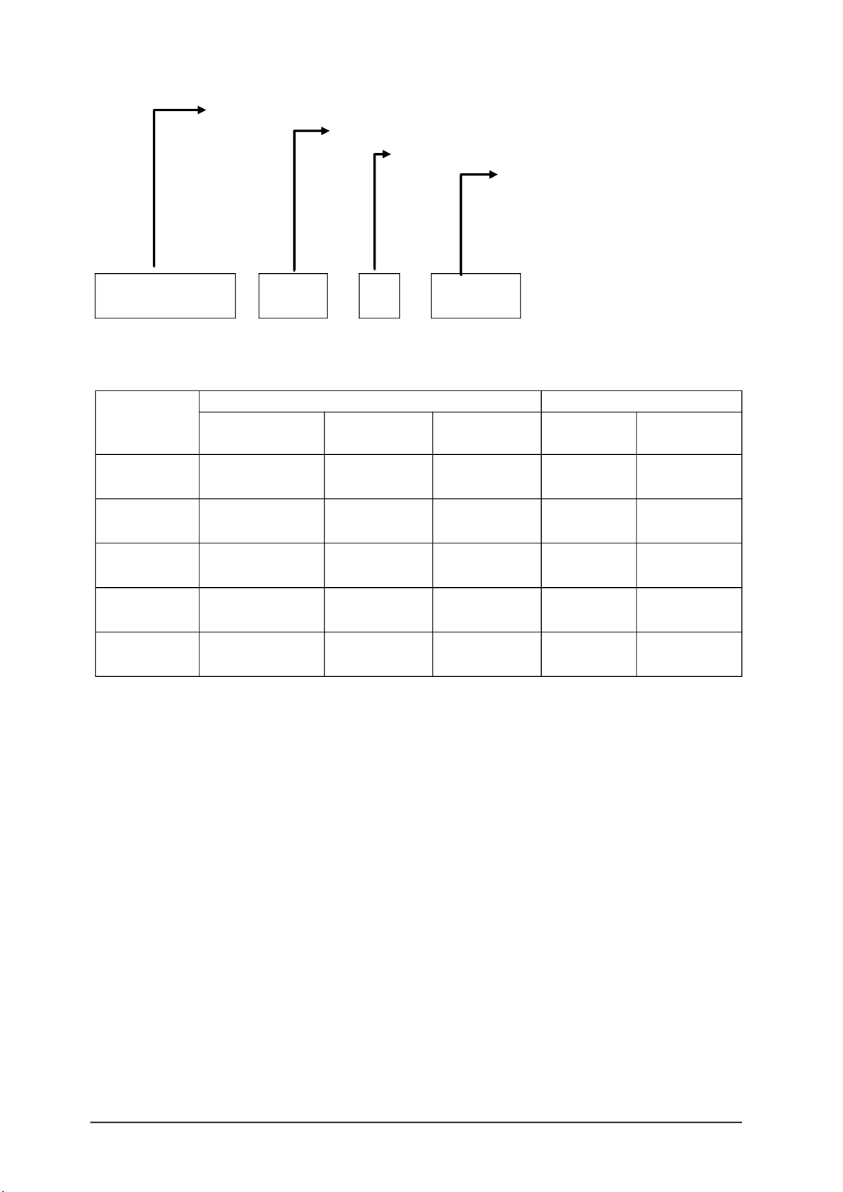
Model designation and options codification
Type & Model
Nominal Voltage
Nb of Phase
Opons
MB Mounng Bracket
FS Floor Stand
BBACnet RS485
RT Roof top enclosure
ISE 100 - 120 / 1 - MB
ISE capacity & power requirement
Model
Steam Capacity Power requirement
5PSI
[34kPa]
10PSI
[69Kpa]
15PSI
[103kPa] Power Voltage
ISE30 4lb/h
[1.8kg/h]
15lb/h
[6.8kg/h]
30lb/h
[13.6kg/h] 100W 120Vac/1ph
or 240/1ph
ISE60 7b/h
[3.2kg/h]
30b/h
[13.6kg/h]
60b/h
[27.3kg/h] 100W 120Vac/1ph
or 240/1ph
ISE100 12b/h
[5.4kg/h]
50b/h
[22.7kg/h]
100b/h
[45.4kg/h] 100W 120Vac/1ph
or 240/1ph
ISE200 24lb/h
[10.9kg/h]
100lb/h
[45.4kg/h]
200lb/h
[90.9kg/h] 100W 120Vac/1ph
or 240/1ph
ISE400 48lb/h
[21.8kg/h]
200lb/h
[90.9kg/h]
400b/h
[181.8kg/h] 2x 100W 120Vac/1ph
or 240/1ph
9
O V E R V I E W
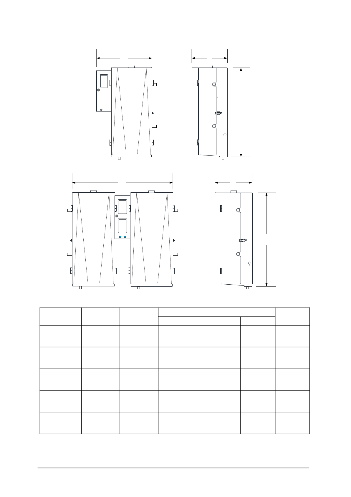
ISE Dimensions
W
H
D
Figure 3 – ISE Dimensions , single module
W
H
D
Figure 4 – ISE Dimensions , two modules , model ISE400
Model Nb Cyl
+ size
Nb Steam
Outlet + Ø Dimensions Net
weight
W H D
ISE30 1x
small
1x 2in
[DN40]
27-1/4in
[682mm]
35in
[875mm]
18-1/4in
[456mm]
80lb
[36kg]
ISE60 1x
medium
1x 2in
[DN50]
27-1/4in
[682mm]
35in
[875mm]
18-1/4in
[456mm]
85lb
[38kg]
ISE100 1x
medium
1x 2-1/2in
[DN65]
27-1/4in
[682mm]
40in
[1000mm]
18-1/4in
[456mm]
100lb
[45kg]
ISE200 1x
large
1x 3-1/2in
[DN90]
27-1/4in
[682mm]
46in
[1150mm]
18-1/4in
[456mm]
120lb
[55kg]
ISE400 2x
large
2x 3-1/2in
[DN90]
27-1/4in
[682mm]
46in
[1150mm]
18-1/4in
[456mm]
270lb
[122kg]
10
I N S T A L L A T I O N
Installation overview
General
1. Installaon of this humidifier should be carried out by trained and qualified personnel.
2. Any work related to installaon of this humidifier must comply with local code and
regulaon regarding safety and prevenon of accidents.
WARNING. Risk of electric shock.
Power supply must be disconnected during installaon.
Main power should be connected only aer all installaon steps have been
completed and properly verified.
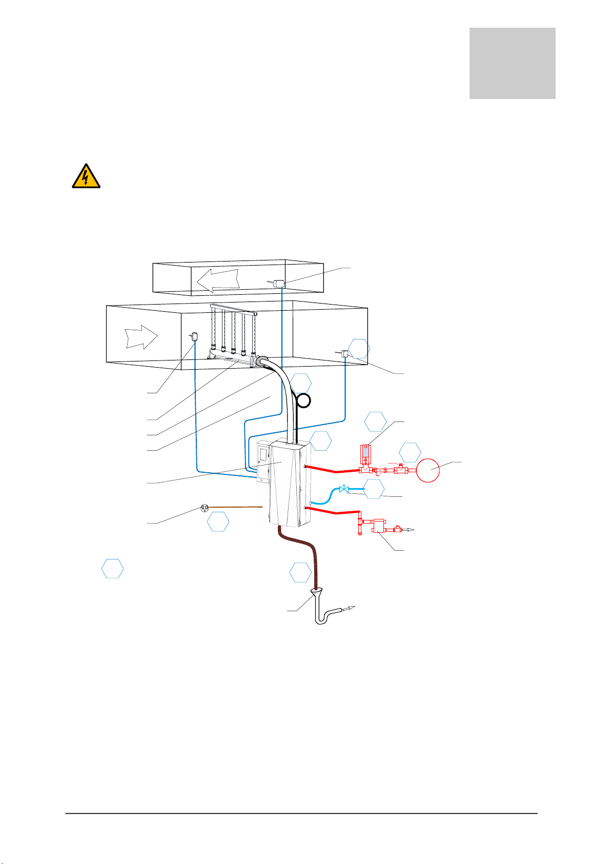
Typical installation with steam ramp
Air
RETURN
RH% Sensor
HI-Limit RH% switch
ISE Steam exchange
Humidifier
Open & deported Drain
with P Trap
Air flow switch
Power supply
Shut-off valve on
water supply line
SOS Mul-ramp
Steam line (hose) 1
2
3
4
5
8
0Installaon steps
Air
SUPPLY
Condensate line
(hose)
6
Control valve
Pressurized steam
(raw steam)
Steam trap
Non pressurized
condensate
Main drain
(waste water)
7
Figure 5 – installaon overview
Typical installation steps:
1. Posioning & mounng of ISE steam exchange humidifier
2. Water supply installaon
3. Drain installaon
4. Pressurized steam & condensate return lines installaon
5. Atmospheric steam line installaon for duct humidificaon
6. Power supply installaon
7. Actuated control valve connecon
8. Safety & RH% control installaon
11
section
3

I N S T A L L A T I O N
Installation – step 1
Positioning & Mounting
General guidelines for positioning
ISE steam exchange humidifier should be posioned so that:
Length of the steam line (or hose) is as short as possible,
In case steam hose is used, the bend radius of 12in (300mm) is ensured
Humidifier is easily accessible for service
CAUTION. Risk of malfuncon due to vibraon. Do Not mount ISE steam exchange
humidifier directly on venlaon duct.
CAUTION. Risk of flooding. Ensure that the local where ISE steam exchange
humidifier will be installed is equipped with floor drain.
In case of no floor drain is available; installaon of a water leak detector is required
in order to prevent any flooding in case of abnormal operaon or service.
ISE steam exchange humidifier should be installed in a well-venlated and dry environment.
If local is subject to below freezing point temperature, acvaon of ant freezing funcon of
the ISE steam exchange humidifier is required.
For outdoor installaon please contact your steamOvap representave to order and install
special outdoor oponal enclosure for IER.
ISE maximum ambient condions:
Temperature: 41°F to 113°F [+5 to +45°C]
Relave Humidity: 90%RH max (non condensing)
Ingress Protecon for ISE standard enclosure: IP20
12

I N S T A L L A T I O N
Clearances
[ ]
[ ]
Min. 36in
900mm
Figure 6 – minimum clearances
Clearance guidelines
There is no minimum clearance on le side of the ISE steam exchange humidifier, but it is a
good pracce to have a clearance of 4 to 8 in [100 to 200mm] for ease of installaon and
service.
Right side clearance of 36in (900mm) minimum is required to the steam exchanger
connecon to steam supply and condensate return piping.
In case of a 2 modules ISE [model ISE400] same clearance, 36in [900mm], is required on both
side of the ISE humidifier.
Allow a minimum clearance of 24in [610mm] with floor to allow for proper drain slope and
drain pipe column.
Top clearance is required of 12in [300mm] for access and proper steam connecon
Front clearance of 30in [762mm] is required for access to the ISE steam exchange humidifier
13
I N S T A L L A T I O N
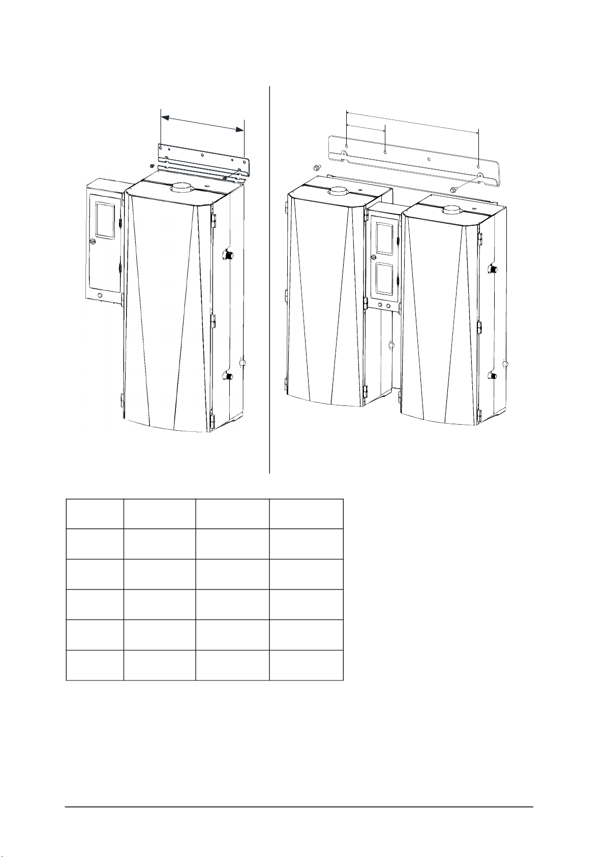
Wall Mounting bracket & weight
15in
[381mm]
Figure 7 mounng bracket for single
module (ISE30 to 200)
36-1/2in [913mm]
12in
[300mm]
Figure 8 – 2 modules mounng bracket
(ISE400)
Weight
Model Nb Cyl + size Net Weight Oper. Weight
ISE30 1x
small
80lb
[36kg]
145lb
[66kg]
ISE60 1x
medium
85lb
[38kg]
159lb
[72kg]
ISE100 1x
medium
100lb
[45kg]
200lb
[91kg]
ISE200 1x
large
120lb
[55kg]
240lb
[109kg]
ISE400 2x
large
270lb
[122kg]
506lb
[230kg]
14

I N S T A L L A T I O N
General guidelines for Mounting
CAUTION. Risk of malfuncon. ISE steam exchange humidifier must be levelled
in X & Z axis.
Installaon on wall, with mounng bracket
1. Verify that wall structure and strength is appropriate to support the operang weight
of the ISE steam exchange humidifier.
In case that wall is not solid enough to support operang weight of ISE humidifier,
install it on a floor stand (FS opon is available to your steamOvap representave).
2. Mark the wall or support according as per below drawing, Drill holes to the wall or
support to aach the mounng bracket to the wall as per the size of anchors and/or
screws.
Distance between the 2 holes in Mounng bracket is 15in [381mm] for ISE30 to ISE200
36-1/2in [913mm] for ISE400
3. Use anchors of sufficient size (at least 3/8in [9m]). Install the mounng bracket to the
wall or support.
Ensure that the mounng bracket is properly levelled.
4. With front cover removed, hung the ISE humidifier onto the mounng bracket.
5. Install the 2 supplied screws to avoid the ISE steam exchange humidifier to move up
from the mounng bracket.
Installaon on Floor Stand (opon FS)
1. Ensure that the floor structure and strength is appropriate to support the operang
weight of the ISE humidifier.
2. Aach the floor stand to the floor or structure to avoid any movement of the ISE
humidifier.
You can use bolt or screws to aach this one to surrounding structure or to the floor.
3. Install Humidifier (with front cover removed) hung the ISE humidifier onto the FS floor
stand and secure it with supplied bolts.
4. Re-install the front cover to the humidifier.
15
I N S T A L L A T I O N
Installation – step 2
Water supply installation
Water supply specification & quality:
Water supply pressure: 15 to 80PSI [1 to 5bar]
Water supply temperature: 37 to 105°F [3 to 40°C]
ISE steam exchange humidifier can accept a wide range of water quality.
Untreated water will lead to scale deposits that will need to be regularly removed from steam
chamber.
Use of addives such as scale inhibitor or corrosion inhibitors, disinfectants or other can
impair the normal operaon of the humidifier and are not allowed.
Water supply conducvity: 1 to 1500µS/cm
Water supply hardness: 0 to 16grains/gallon [0 to 15°gH][268mg CaCO3/l]
Water supply PH: 6.5 to 7.5
Water supply chloride content: 0 to 50ppm
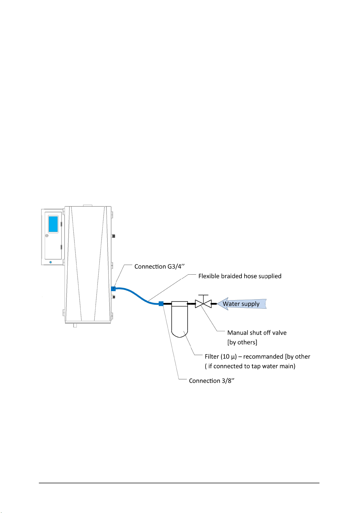
( µ – [ ]
)
[ ]
3/8'
3/4
Figure 9 – water supply connecon, single module
16
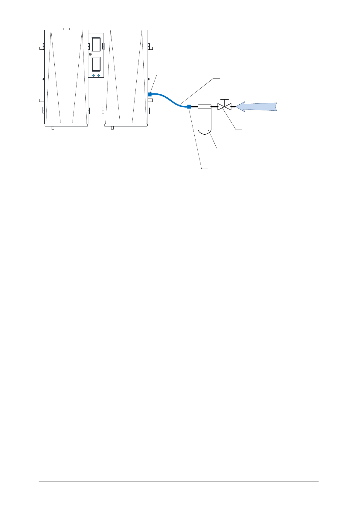
I N S T A L L A T I O N
Flexible braided hose supplied
Water supply
Filter (10 µ) – recommanded [by others]
( if connected to tap water main)
Manual shut off valve
[by others]
Connecon 3/8'’
Connecon
NPT½ female
Figure 10 – water supply connecon, 2 modules ISE400
Water supply connection:
1. Install a manual; shut off valve on the water main line.
2. If ISE humidifier is supplied with tap water it is recommended to install a 10µ sediment
filter on the line. This filter will protect internal water fill valve from clogging.
3. A flexible braided hose is supplied for an easy and secure connecon to the water
supply inlet.
17
I N S T A L L A T I O N
Installation – step 3
Drain installation
Water drained specification:
Drained water maximum temperature: 140°F [60°C]
when supplied with cold water supply
Drained water flow rate: 6.6 GPM [25 l/min]
Drain outlet dimension: ISE30 to 200: (1x)1-1/4in [32mm]
ISE300 & 400: (2x)1-1/4in [32mm]
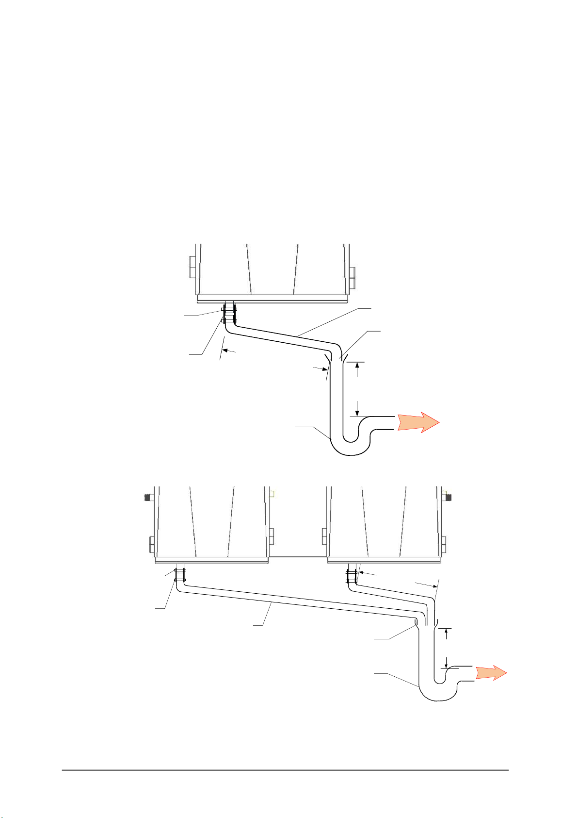
ISE Humidifier
Drain
Connecon sleeve
1-1/4in [DN32] (supplied)
Slope minimum 5°
P trap
Open drain offset from ISE
1-1/2in [DN40] minimum
2 collars
(by others)
12in
[30cm] minimum
Vercal Length 18in
[45cm] minimum
Figure 11 – water drain connecon, single module
Connecon sleeve
1-1/4in [DN32] (supplied)
2 collars
(by others)
Drain
Slope minimum 5°
P trap
Open drain offset from ISE
2in [DN50] minimum
12in [30cm]
minimum
18in [45cm]
minimum
ISE Humidifier
Module 2Module 1
Figure 12 – water drain connecon, 2 modules ISE400
18

I N S T A L L A T I O N
Installation steps:
1. Ensure that an Open drain with a P-trap is installed offset from the ISE humidifier.
IMPORTANT: Risk of malfuncon. A minimum slope angle of 5 degree of the drain
hose or pipe and a minimum length of 12in [30cm] must be provided between the
drain outlet of the ISE humidifier and the open drain inlet.
A minimum of 18in [45cm] vercal run before P trap or obstrucon must be provided
2. If required, install a connecon sleeve 1-1/4 [32mm] at the drain outlet of the ISE
humidifier to the drain pipe, and secure it with 2 collars.
19

I N S T A L L A T I O N
Installation – step 4
Pressurized steam & condensate
installation
Pressurized steam supply piping must conform to local codes and regulaons.
Risk of damage to ISE humidifier. Steam piping should be supported to avoid stress to
steam components and/or ISE humidifier heat exchanger.
Pipes should be free from dirt.
Pressurized steam line installaon should be performed by a qualified installer.
Nipple & union (by others)
Electric actuated control
valve (supplied)
Strainer (supplied)
Manual shut-off valve (by others)
Raw steam supply
Nipple & union (by others)
F&T steam trap (supplied)
Check valve (by others)
Non-pressurized condensate return
Vacuum breaker (by others)
ISE steam exchange
humidifier
Figure 13 – Pressurized steam & condensate connecon
Pressurized steam installation:
ISE humidifier heat exchanger is designed for a maximum steam pressure of 15PSI (105kPa).
Pressurized steam line must be sized to provide design pressure and flow at the CV valve at
full output. Pressure losses in the steam supply line will reduce ISE pure steam capacity.
Actuated steam control valve should be lted to reduce the heat transfer from steam pipe to
the electric actuator. Please refer to below illustraon.
It is a good pracce to install the following components:
•Strainer (supplied) and a manual shut-off valve upstream to the control valve .
•Manual shut-off valve and pressure gauge (by others) upstream to the actuated
control valve.
•Vacuum breaker (by others) between actuated control valve and ISE heat exchanger
inlet and at any high point of the pressurized steam piping
•nipple and union (by others) to the inlet and outlet of the ISE heat exchanger for ease
of service.
20
This manual suits for next models
4
Table of contents
Other SteamOvap Humidifier manuals


Popular Humidifier manuals by other brands


Nordmann
Nordmann ES4 Installation operation & maintenance

Steba
Steba LB 5 Instructions for use

Levoit
Levoit OasisMist LUH-O451S-WUS user manual

Honeywell
Honeywell HCM 800 - PermaFresh Cool Moisture... user manual

HygroMatik
HygroMatik Basic-DS manual

Field Controls
Field Controls SC100 installation instructions