SteamOvap ACA Series User manual

ACA – COMPRESSED AIR & WATER ATOMIZING
HUMIDIFIER & AIR COOLER
Installation and Operation Manual
Please read and save this manual
steamOvap technologies inc, 9495 Charles de la Tour, Montreal, Qc, H4N 1M5, Canada
Tel.: 1-844-357-4477 • www.steamOvap.com
Rev.191101
ACA


Introduction
Foreword
Thank you for purchasing ACA steamOvap compressed air & water atomizing humidifier.
If you have quesons or comments please contact us:
www.steamOvap.com
1-844-357-4477
Intended use
ACA Compressed air & water atomizing is intended exclusively to produce cold mist from
water at atmospheric pressure for air humidificaon.
Operang condions are specified in this Installaon and Operaon Manual (IOM).
Operaon of this atomizing in the intended use scope requires that all direcons and
informaon contained in this IOM are observed.
Any other use or operaon outside the above design scope without wrien authorizaon
from steamOvap may lead to trouble and hazardous condions and will void warranty.
No alteraon or modificaon to the atomizing must be done without wrien authorizaon
from steamOvap.
Replacement of any defecve components must be done with original component and spare
parts from steamOvap representave.
Installation and Operation Manual Limitation
This IOM is intended for trained and qualified personnel and must be applied along with the
applicable local codes and regulaons.
Any work related to installaon or service for this atomizing must comply with local code and
regulaon regarding safety and prevenon of accidents.
End of life disposition
Ensure that ACA Compressed air & water atomizing humidifier is empty from water, if not
proceed empty all pipes, hoses and valves.
Disconnect ACA Compressed air & water atomizing humidifier from power supply, electrical
control signal, water main supply, ACA Compressed air & water atomizing humidifier can then
be removed from the wall or stand.
ACA Compressed air & water atomizing humidifier is an electrical equipment and as such
MUST not be disposed of in domesc waste.
This humidifier should be returned to the closest steamOvap authorized representave for
proper dismantling, recycling and disposion of components according to local regulaons.
3

Table of content
Introduction................................................................................................3
Table of content.........................................................................................4
Safety warnings.........................................................................................5
Before to proceed to Installation................................................................6
ACA Overview...........................................................................................7
ACA-Distribution panel Dimensions & weight............................................9
Typical installation in-space overview......................................................10
Installation – step 1 ACA Dist. panel positioning & mounting...................11
Installation – step 2 Water supply installation..........................................13
Installation – step 3 Compressed air installation......................................15
Installation – step 5 ACA control panel installation..................................16
Installation – step 6 Control installation....................................................17
Verification before start-up.......................................................................18
Configuration & Operation.......................................................................19
Service....................................................................................................xxi
Warranty.................................................................................................xxii
4

S A F E T Y
Safety warnings
General
Risk of electric shock.
Disconnect power supply before installaon or service.
For safety and warranty reasons, Installaon and service of this humidifier should be
carried out by trained and qualified personnel.
Any work related to installaon and service of this humidifier must comply with local code
and regulaon regarding safety and prevenon of accidents.
Electrical Warning
Risk of electric shock.
Disconnect power supply before installaon or service.
Power supply connecon must be done by a trained and qualified electrician.
Water safety warning
Any work related to water supply, drain connecon or service of such for this atomizing
humidifier must comply with local code and regulaon regarding safety and prevenon of
accidents.
Water supply connecon must be done by a trained and qualified plumber.
Risk of disease: ACA atomizing humidifier should be connected to a clean,
wholesome mains water supply. Installer and user are responsible to ensure that
the water supply system complies with local regulaons in regards to Legionella
prevenon and any other microbiological growth prevenon,
Building owner and end user should carry-out a risk analysis and put in place a prevenon
plan to avoid any microbiological growth such as legionella.
Compressed air safety warning
Any work related to compressed air connecon or service of such for this atomizing
humidifier must comply with local code and regulaon regarding safety and prevenon of
accidents.
Compressed air supply connecon must be done by a trained and qualified plumber.
Others
Risk of flooding. In order to avoid any risk of flooding steamOvap recommends a Hi
limit humidity switch installed in the air duct downstream of the distribuon ramp.
Risk of freezing. Plan an an-freeze system in case of installaon in a locaon that
would be exposed to outside condions and suscepble of freezing.
Risk of malfuncon. Do not block outlet(s).
5
section
0

I N T E N D E D U S E
Before to proceed to Installation
Please read this Installation and Operation manual before to proceed to the Installation
Receiving & Unpacking
1. Upon receipt verify that packaging is complete and not damaged.
In case of damage, and/or missing boxes advise immediately the carrier by wring a
note on the waybill.
2. Verify that model of the humidifier matches the purchase order and that all
accessories are included.
3. Any missing item should be reported as soon as possible to steamOvap or its
representave and within 5 business days aer receipt.
steamOvap will not assume any responsibility for missing item aer this delay.
4. Proceed carefully to unpacking, and check that the humidifier and its accessories are
not damaged. in case of damage please proceed as for point 3
Included in standard delivery of ACA Compressed air &
water atomizing humidifier
1. ACA Compressed air & water atomizing humidifier
2. Mounng brackets
3. ACA Controller
4. This IOM
Depending on model
5. In duct manifold
6. Compressed air hose
7. Water hose
8. RH% sensor
6
section
1

O V E R V I E W
ACA Overview
ACA Compressed air & water atomizing humidifier
Figure 1 – ACA Overview
ACA product designation & name plate
Figure 2 – ACA Name plate
7
section
2

I N S T A L L A T I O N
Product designation
Type Model Nozzle qty Capacity Comment
In space ACA-S2 2 26lb/h
In space ACA-S4 4 53lb/h
In space ACA-S6 6 78lb/h
In duct ACA-DHPP 1 to 6 13 to 78b/h
In duct ACA-NOZZ6 1 13 b/h Nozzle only
Control panel ACA-OCUx n/a n/a For 1 or 2 zones
Electrical rating
Type Model Nozzle
Qty Capacity Rated
power
Voltage &
nb of
phase
Rated
current
In-space ACA-S2 2 26lb/h 15W 24Vdc 0.6A
In-space ACA-S4 4 53lb/h 15W 24Vdc 0.6A
In-space ACA-S6 6 78lb/h 15W 24Vdc 0.6A
In duct ACA-DHPP 1 to 6 13 to 78b/h 15 W 24Vdc 0.6A
-ACA-OCUx - - 15W 120Vac/1p 0.13A
Compressed air requirement
Type Model Capacity Air pressure Air consumpon
In-space ACA-S2 2 26lb/h 87 to 100PSI 4 cfm @ 87PSI
In-space ACA-S4 4 53lb/h 87 to 100PSI 8 cfm @ 87PSI
In-space ACA-S6 6 78lb/h 87 to 100PSI 12 cfm @ 87PSI
In duct ACA-DHPP 1 to 6 13 to 78lb/h 87 to 100PSI 2 to 12 cfm @
87PSI
Water supply requirement
Pressure:
40 to 60PSI [2.8 to 4bar] hammer free
Temperature:
37 to 68°F [3 to 20°C]
Untreated water requirement Pure water requirement
Water supply conducvity: 1 to 156µS/cm
Water supply TDS: 0 to 100 ppm TDS max
Water supply PH: 6.5 to 7.5
Water supply chloride content: 0 to 50ppm
Water supply conducvity: 0.1 to 0.5µS/cm
Water supply TDS: 0.02 to 0.2 ppm TDS min
Water supply PH: 6.5 to 7.5
8

I N S T A L L A T I O N
ACA-Distribution panel
Dimensions & weight
16in
20in
8in
4in
Figure 3 – ACA-Sx dimensions
Model Capacity Nb
Nozzle
Dimensions Weight
W H D
ACA-S2 26lb/h 2 16in 24in 8in 24lb
[11kg]
ACA-S4 53lb/h 4 16in 24in 8in 26lb
[13kg]
ACA-S6 78lb/h 6 16in 24in 8in 28lb
[13kg]
ACA-DHPP 1 to 6 13 to
78lb/h 16in 20in 8in 22lb
[10kg]
ACA maximum ambient conditions & IP rating
Temperature: 38°F to 113°F [+3 to +45°C]
Relave Humidity: 95%RH max (non condensing)
Ingress Protecon for ACA standard enclosure: IP42
9

I N S T A L L A T I O N
Typical installation in-space
overview
General
1. Installaon of this atomizing humidifier should be carried out by trained and qualified
personnel.
2. Any work related to installaon of this atomizing humidifier must comply with local
code and regulaon regarding safety and prevenon of accidents.
WARNING. Risk of electric shock.
Power supply must be disconnected during installaon.
Main power should be connected only aer all installaon steps have been
completed and properly verified.
5
3
4
1
2
Figure 3 –ACA typical installaon
installation steps:
Posioning& mounng of ACA in space distribuon panel
Water supply installaon
Compressed air installaon
ACA control panel installaon
RH% control installaon
10
section
3

I N S T A L L A T I O N
Installation – step 1
ACA Dist. panel positioning &
mounting
General guidelines for positioning
ACA in space distribuon panel should be posioned so that:
Unintenonal weng cannot occur on equipment, material or building surface or
people. A ceiling height of 9 [2.7m] minimum is recommended.
Humidifier is easily accessible for service
CAUTION. Risk of flooding. Ensure that the space where ACA Compressed air &
water atomizing humidifier will be installed is equipped with floor drain.
In case of no floor drain is available; installaon of a water leak detector is required
in order to prevent any flooding in case of abnormal operaon or service.
ACA Compressed air & water atomizing humidifier should be installed in a well-venlated and
dry environment.
If local is subject to below freezing point temperature, an freezing disposion such as heat
trace on any water carrying device and pipe is required.
Clearances
24in
[60cm]
8-1/2
[2.5m]
Figure 4 – minimum clearances
11

I N S T A L L A T I O N
Clearance guidelines
There is no minimum clearance on both side of the ACA distribuon panel, but it is a good
pracce to have a clearance of 4 to 8 in [100 to 200mm] for ease of installaon and service
Allow a minimum clearance of 24in [60cm] with ceiling.
Front clearance of 8-1/2 [2.5m] in front of nozzle is required to avoid any unintenonal
weng on surfaces, equipment, wall, or people.
It is a good pracce to install ACA in space distribuon panel where ceiling height is 9
[2.7m]minimum
Mounting holes positions
Figure 5 – ACA distribuon panel mounng holes posion
General guidelines for Mounting
CAUTION. Risk of malfuncon. ACA distribuon panel must be levelled in X & Z axis.
Installaon on wall
1. Verify that wall structure and strength is appropriate to support the weight of the
ACA distribuon panel.
2. Mark the wall or support according to the holes locaon as per the above figure , and
drill 4 holes to the wall or support as per the size of anchors and/or screws.
3. Use anchors of sufficient size (at least 1/4in [6mm]). Insert those anchors and the 2 top
screws. Then hung the ACA distribuon panel onto the 2 top screws.
Ensure that the humidifier is properly levelled.
4. Insert the 2 boom screws and ghten them up. Re verify the level in the 2 direcon X
and Z axis.
1. Tighten the 4 screws.
12
I N S T A L L A T I O N
Installation – step 2
Water supply installation
Water supply specification& quality:
Water supply pressure: 40 to 60PSI [2.8 to 4bar] – hammer free
Water supply temperature: 37 to 68°F [3 to 20°C]
ACA Compressed air & water atomizing humidifier can accept a wide range of water quality.
Important: the use of untreated water will lead to fine parcles deposit with the atomized
water, resulng is fine powder deposit in surrounding surfaces or air filter.
ACA should be connected to a clean, wholesome mains water supply. Installer and user are
responsible to ensure that the water supply system complies with local regulaons in regards
to Legionella and any other microbiological growth prevenon,
A 1μm sediment filter and a silver ions anbacterial cartridge or UV sterilizer must be installed
on the water supply line.
Untreated water requirement Pure water requirement
Water supply conducvity: 1 to 156µS/cm
Water supply TDS: 0 to 100 ppm TDS
Water supply PH: 6.5 to 7.5
Water supply chloride content: 0 to 50ppm
Water supply conducvity: 0.1 to 0.5µS/cm
Water supply TDS: 0.02 to 0.2 ppm TDS
Water supply PH: 6.5 to 7.5
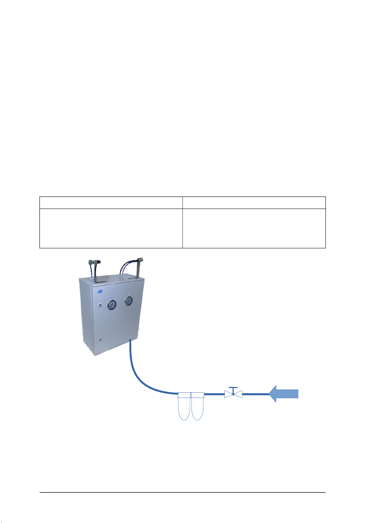
Figure 6 – water supply connecon
13
2 stages filter (1μm)
+ silver ions (anbacterial)
or UV sterilizer
Shut off valve
(by others)

I N S T A L L A T I O N
Water supply connection:
1. Install a manual; shut off valve on the water main line.
2. If ACA distribuon panel is supplied with tap water it is recommended to install a 5µm
sediment filters on the line. This filter will protect internal water components from
clogging.
3. ACA atomizing humidifier is supplied with 2 stages filters 1µm & anbacterial silver
ions cartridge. Install this pre-filter on the water main line downstream of the manual
shut-off valve.
4. Connect water supply to the 3/8in compression fing connecon. located at the
boom of ACA distribuon panel and secure the water line.
5. Ensure that the water line is hammer free and leak free.
Important: In case ACA atomizing humidifier is Off for more than 24hours, user should be
able to isolate the water main supply line and drain the ACA water supply line in order to
avoid any stagnant water and associated risk of legionella growth.
14

I N S T A L L A T I O N
Installation – step 3
Compressed air installation
Compressed air specification& quality:
Water supply pressure: 87 to 100PSI [6 to 7bar]
Air supply should be clean, dry and free from oil.
In case dirt or oil is contained in air supply, an air filter and oil separator should be installed.
Any oil collector should be connected to an oil drain.
To prevent bacterial growth, compressed air piping should be non-corrosive and any joinng
material should be inorganic.
Figure 7 Compressed air installaon
Compressed air connection:
6. Install a manual shut off valve on the compressed air line.
7. Install an air filter and oil separator on the line. This filter will protect ACA internal
component and avoid spraying oil in the air.
8. Connect compressed air to the universal quick coupling M type 1/4 connecon.
located at the boom of ACA distribuon panel and secure the compressed air line.
9. Ensure that the compressed air line is leak free.
15
Air filter & oil separator (by others)

I N S T A L L A T I O N
Installation – step 5
ACA control panel installation
Electrical Warning
Risk of electric shock.
Disconnect power supply before installaon or service.
General guidelines for ACA control panel positioning
ACA control panel should be posioned so that:
Unintenonal weng cannot occur the control panel
Control panel is easily accessible for set-up and control of the ACA distribuon panel
and atomizing
It is protected from sun and rain
Maximum length of cable to ACA distribuon panel and to RH% & Temp sensor is 30
[9m].
Power supply specification:
ACA Control panel is supplied with power cord and standard 120Vac plug.
ACA Distribuon panel is supplied from the ACA control panel at extra low voltage 24Vdc
refer to below diagram for electrical connecon of ACA distribuon panel.
ACA electrical rating
Type Model Rated power
Voltage &
nb of
phase
Rated
current
-ACA-OCU 15W 120Vac/1p 0.13A
In-space ACA-S2, S4, S6, or DHPP 15W 24Vdc 0.6A
16

I N S T A L L A T I O N
Installation – step 6
Control installation
General guidelines for control installation
RHS-P420 should be placed in a locaon where the air is properly mixed and represensave of
the air condion in the room
Connect ACA-Sx or DHPP and RHS-P420 according to below diagram
L
Main supply teminal
120Vac / 1ph
N Gnd
24Vdc +
RH signal
RH & T #1
OCU1
Air & Water
To Dist Pan.
ACA-S or DHPP
Distribuon panel
ACA-OCU1 or 2
Control panel
(by others)
(by others)
+ -
RH1
T1
WATER1 -
WATER1 +
AIR 1 -
AIR 1 +
FAN1
FAN1
B OUT
A OUT
B IN
A IN
Temp signal
4-20mA
signal
AIR +
WATER +
COMMON
RHS-P420
RH% & Temp.
sensor
T V+ RH
Air proving switch
(by others)
Figure 8 – Control connecon
17

I N S T A L L A T I O N
Verification before start-up
Warning
For safety and warranty reasons, Installaon and service of this ACA atomizing humidifier
should be carried out by trained and qualified personnel.
Any work related to installaon and service of this atomizing humidifier must comply with
local code and regulaon regarding safety and prevenon of accidents.
Risk of electric shock.
Disconnect power supply before verificaon.
Risk of floofing: Ensure that the space where ACA Compressed air & water
atomizing humidifier will be installed is equipped with floor drain.
In case of no floor drain is available; installaon of a water leak detector is required
in order to prevent any flooding in case of abnormal operaon or service.
Risk of damage due to weng : Plan for proper clearance in front and below ACA
distribuon panel and nozzle in order to avoid any unintenonal weng on
surfaces, equipment, wall, or people.
Risk of freezing. Plan an an-freeze system (heat trace) in case of installaon in a
locaon that would be exposed to condions suscepble of freezing.
Risk of malfuncon. Do not block nozzle orifice(s).
Check list
Mounng
oCheck mounng to verify that the ACA distribuon panel is level and securely
supported before filling with water.
oVerify that ACA control panel and RH% and /or Temperature sensor are
installed and connected.
Water supply
oVerify that all piping connecons have been completed as recommended and
that water pressure is available.
oEnsure that 2 stages Pre-filter 1µm + an-bacterial silver ions cartridge is
installed.
oOnce water shut off valve is open, verify for any possible leak.
Compressed air
oVerify that compressed air piping have been completed that Air pressure is
available.
oEnsure that an air filter and oil separator have been installed on the line.
oOnce Air shut off valve is open, verify for any possible leak.
Power supply
oVerify that 120Vac electrical is available for the supply of ACA control panel
oCheck that ACA distribuon panel and RH% and/or Temperature sensor have
been wired to the ACA control panel.
Control circuit
oVerify that safety controls such as Hi limit humidistat and/or enable switch
and/or floor leak detector have been connected.
oVerify that RH% and Temperature sensor is connected to the control terminals.
Once all above verificaon has been completed and found sasfactory you can powered up
the ACA atomizing humidifier.
18
section
4

C O N F I G U R A T I O N & O P E R A T I O N
Configuration & Operation
Control panel overview
Figure 9 – Control panel
Control panel allows you to set-up and control the ACA Compressed air & water atomizing
humidifier.
Control panel standard set-up
Steps Screen Descripon
01 When powered the display will indicate actual RH% and
Temperature.
02 By pressing Right arrow LCD display will indicate the
RH% set point
03 Pressing right arrow again will display the on/off pulse
of the air and water valves
04 Pressing right arrow will display the password request
to enter programming mode
19
section
5

C O N F I G U R A T I O N & O P E R A T I O N
Programming mode
Steps Screen Descripon
Default password is 12345 Press enter once value is entered
A Press 1, for User mode
B Enter desired Set point and press enter
C
You can select by pressing the down arrow between:
‘’No’’ or ‘’with’’, then press enter
Pulses are recommended for smaller space
DIf With pulses is selected
enter the Pulse ON period in seconds
E Enter then the Pulse OFF period in seconds
F
Air valve closing should be delayed by 10 to 20 seconds
aer water valves
this period can be adjusted depending on the water hose
length, longer the hose length is londer the delay should
be.
This delay can be set-up in the technician mode.
The Delay On should be set a 0sec, Delay Off will delay the
closing of the Air valve to the desired valu.
Once all sengs have been entered, you should put the control panel off by switching
the main switch to Off for few seconds and put it back On
Once back On, press for few second on the buon ‘’i’’ unl the ‘’SYSTEM’’ is
displayed.
Press enter , then press le arrow unl ‘’RESET’’ is displayed, press again enter
.
Controller will perform a reset. Once reset is complete, press on the right arrow 2
mes to verify that the seng are recorded.
Make sure that the flip switch ‘’A/M”” located inside the control panel beside the control
terminal is on the ‘’A’’ posion for Automac
Operation mode
Once Control panel is ON, press on the ON/OFF green push buon to put the ACA atomizing
humidifier on Automac mode.
20
This manual suits for next models
6
Table of contents
Other SteamOvap Humidifier manuals


