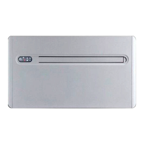
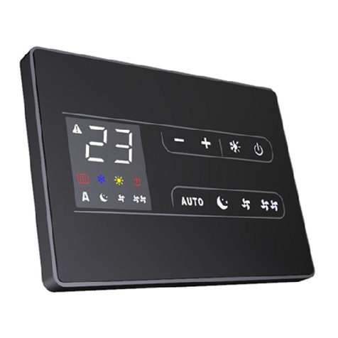
Innova 2.0 15HP User guide

ENInstaller manual
15 HP DC Inverter

2
Markings
Conformity
This unit complies with the European directives:
• EN 60335-2-40 Household and similar electrical applianc-
es - Safety Part 2-40: Particular requirements for electrical
heat pumps, air-conditioners and dehumidiers
• Low Voltage Directive 2014/35/EU according following
technical norms and their subsequent
• EMC Directive 2014/30/EU, according following technical
norms and their subsequent
• RED Directive 2014/53/UE on the harmonisation of the
laws of the Member States relating to the making available
on the market of radio equipment
• RoHS Directive 2011/65/EU
• Directive 2017/1369/EU on energy labelling
• 2009/125/EU Directive and implementing regulation
206/2012/EU and Italian implementing regulation Legisla-
tive Decree no. 15 of 16/02/2011
• F-Gas Regulation 2014/517/EU on uorinated greenhouse
gases
And subsequent amendments.
For declarations of conformity, certicates and other certi-
cation details please consult the website.
First of all, we would like to thank you for having chosen a device of our production.
We are sure you will be happy with it because it represents the state of the art in the technology of
home air conditioning.
By following the suggestions contained in this manual, the product that you have purchased will
operate without problems giving you optimum room temperatures with minimum energy costs.
INNOVA S.r.l.

3
TABLE OF CONTENTS
1 General � � � � � � � � � � � � � � � � � � � � � � � � � � � � � � � � � � � � � � � � � � � � � � � � � � � � � � � � � � � � � � � � � � � � � � � � � �p.5
1.1 Symbols . . . . . . . . . . . . . . . . . . . . . . . . . . . . . . . . . . . . . . . . . . . . . . . . . . . . . . . . . . . . . . . p.5
1.2 About the manual . . . . . . . . . . . . . . . . . . . . . . . . . . . . . . . . . . . . . . . . . . . . . . . . . . . . . . . . . p.5
1.3 Recipients . . . . . . . . . . . . . . . . . . . . . . . . . . . . . . . . . . . . . . . . . . . . . . . . . . . . . . . . . . . . . . p.6
1.4 General warnings . . . . . . . . . . . . . . . . . . . . . . . . . . . . . . . . . . . . . . . . . . . . . . . . . . . . . . . . . p.6
1.5 Basic rules of security . . . . . . . . . . . . . . . . . . . . . . . . . . . . . . . . . . . . . . . . . . . . . . . . . . . . . . . p.7
1.6 Disposal . . . . . . . . . . . . . . . . . . . . . . . . . . . . . . . . . . . . . . . . . . . . . . . . . . . . . . . . . . . . . . . p.7
1.7 Identification . . . . . . . . . . . . . . . . . . . . . . . . . . . . . . . . . . . . . . . . . . . . . . . . . . . . . . . . . . . . p.7
1.8 Destination of use . . . . . . . . . . . . . . . . . . . . . . . . . . . . . . . . . . . . . . . . . . . . . . . . . . . . . . . . . p.8
1.9 Description of the appliance . . . . . . . . . . . . . . . . . . . . . . . . . . . . . . . . . . . . . . . . . . . . . . . . . . p.8
1.10 Components . . . . . . . . . . . . . . . . . . . . . . . . . . . . . . . . . . . . . . . . . . . . . . . . . . . . . . . . . . . . p.9
1.11 Compatible accessories . . . . . . . . . . . . . . . . . . . . . . . . . . . . . . . . . . . . . . . . . . . . . . . . . . . . . p.9
2 Installation� � � � � � � � � � � � � � � � � � � � � � � � � � � � � � � � � � � � � � � � � � � � � � � � � � � � � � � � � � � � � � � � � � � � � � p.11
2.1 Preliminary warnings . . . . . . . . . . . . . . . . . . . . . . . . . . . . . . . . . . . . . . . . . . . . . . . . . . . . . . . p.11
2.2 Reception . . . . . . . . . . . . . . . . . . . . . . . . . . . . . . . . . . . . . . . . . . . . . . . . . . . . . . . . . . . . . .p.11
2.3 Dimensions and weights with packaging . . . . . . . . . . . . . . . . . . . . . . . . . . . . . . . . . . . . . . . . . .p.12
2.4 Handling with packaging . . . . . . . . . . . . . . . . . . . . . . . . . . . . . . . . . . . . . . . . . . . . . . . . . . . .p.12
2.5 Storage . . . . . . . . . . . . . . . . . . . . . . . . . . . . . . . . . . . . . . . . . . . . . . . . . . . . . . . . . . . . . . . .p.13
2.6 Unpacking . . . . . . . . . . . . . . . . . . . . . . . . . . . . . . . . . . . . . . . . . . . . . . . . . . . . . . . . . . . . . .p.13
2.7 Handling without packaging . . . . . . . . . . . . . . . . . . . . . . . . . . . . . . . . . . . . . . . . . . . . . . . . . .p.14
2.8 Installation site . . . . . . . . . . . . . . . . . . . . . . . . . . . . . . . . . . . . . . . . . . . . . . . . . . . . . . . . . . .p.14
2.9 Installation minimum distances . . . . . . . . . . . . . . . . . . . . . . . . . . . . . . . . . . . . . . . . . . . . . . . .p.15
2.10 Positioning. . . . . . . . . . . . . . . . . . . . . . . . . . . . . . . . . . . . . . . . . . . . . . . . . . . . . . . . . . . . . .p.16
2.11 Condensation drain preparation . . . . . . . . . . . . . . . . . . . . . . . . . . . . . . . . . . . . . . . . . . . . . . .p.19
2.12 Electric connections . . . . . . . . . . . . . . . . . . . . . . . . . . . . . . . . . . . . . . . . . . . . . . . . . . . . . . .p.21
2.13 High/low installation configuration . . . . . . . . . . . . . . . . . . . . . . . . . . . . . . . . . . . . . . . . . . . . . .p.23
2.14 Setting cooling only or heating only mode. . . . . . . . . . . . . . . . . . . . . . . . . . . . . . . . . . . . . . . . .p.24
2.15 Brightness control . . . . . . . . . . . . . . . . . . . . . . . . . . . . . . . . . . . . . . . . . . . . . . . . . . . . . . . . .p.25
2.16 Touch screen display key lock . . . . . . . . . . . . . . . . . . . . . . . . . . . . . . . . . . . . . . . . . . . . . . . . . p.25
2.17 hotel function. . . . . . . . . . . . . . . . . . . . . . . . . . . . . . . . . . . . . . . . . . . . . . . . . . . . . . . . . . . .p.25
2.18 Operations after installation . . . . . . . . . . . . . . . . . . . . . . . . . . . . . . . . . . . . . . . . . . . . . . . . . .p.25
2.19 Removal of aesthetic panels and grilles . . . . . . . . . . . . . . . . . . . . . . . . . . . . . . . . . . . . . . . . . . .p.25
2.20 Assembly of aesthetic panels and grilles. . . . . . . . . . . . . . . . . . . . . . . . . . . . . . . . . . . . . . . . . . .p.26
3 Maintenance � � � � � � � � � � � � � � � � � � � � � � � � � � � � � � � � � � � � � � � � � � � � � � � � � � � � � � � � � � � � � � � � � � � � p.27
3.1 Preliminary warnings . . . . . . . . . . . . . . . . . . . . . . . . . . . . . . . . . . . . . . . . . . . . . . . . . . . . . . . p.27
3.2 Routine maintenance. . . . . . . . . . . . . . . . . . . . . . . . . . . . . . . . . . . . . . . . . . . . . . . . . . . . . . .p.27
4 Troubleshooting � � � � � � � � � � � � � � � � � � � � � � � � � � � � � � � � � � � � � � � � � � � � � � � � � � � � � � � � � � � � � � � � p.29
4.1 Troubleshooting table . . . . . . . . . . . . . . . . . . . . . . . . . . . . . . . . . . . . . . . . . . . . . . . . . . . . . .p.29
4.2 Displayed faults. . . . . . . . . . . . . . . . . . . . . . . . . . . . . . . . . . . . . . . . . . . . . . . . . . . . . . . . . . .p.29
4.3 Diagnosis of possible anomalies . . . . . . . . . . . . . . . . . . . . . . . . . . . . . . . . . . . . . . . . . . . . . . . .p.29

4
5 Technical information� � � � � � � � � � � � � � � � � � � � � � � � � � � � � � � � � � � � � � � � � � � � � � � � � � � � � � � � � � � � p.31
5.1 Technical data . . . . . . . . . . . . . . . . . . . . . . . . . . . . . . . . . . . . . . . . . . . . . . . . . . . . . . . . . . . p.31
5.2 Dimensions . . . . . . . . . . . . . . . . . . . . . . . . . . . . . . . . . . . . . . . . . . . . . . . . . . . . . . . . . . . . .p.32
5.3 RED Compliance Statement . . . . . . . . . . . . . . . . . . . . . . . . . . . . . . . . . . . . . . . . . . . . . . . . . .p.32
5.4 Safety . . . . . . . . . . . . . . . . . . . . . . . . . . . . . . . . . . . . . . . . . . . . . . . . . . . . . . . . . . . . . . . . .p.32

5
GENERAL
GENERAL
1�1 Symbols
The pictograms in the next chapter provide the necessary
information for correct, safe use of the machine in a rapid,
unmistakable way.
Editorial pictograms
User
• This indicates pages containing instructions or informa-
tion for the User.
Installer
• This indicates pages containing instructions or informa-
tion for the Installer.
Service
• This indicates pages containing instructions or informa-
tion for the Technical Service Centre.
Safety pictograms
Warning
• The operation described above presents a risk of physical
injury if not carried out in compliance with safety regula-
tions.
Dangerous electric voltage
Signals to the personnel that the operation described could
cause electrocution if not performed according to the safety
rules.
Danger of very hot parts
The concerned personnel is informed that the operation de-
scribed above presents a risk of burning due to contact with
hot components if not carried out in compliance with safety
regulations.
Prohibition
• Refers to prohibited actions.
Pictograms related to refrigerant R32
Symbols are used in some parts of the appliance:
Caution: low ammability material
• R32 refrigerant gas is slightly ammable and odourless.
Avoid proximity to sources of ignition in continuous oper-
ation (open ames, gas appliances, electric stoves, lighted
cigarettes, etc.).
Instructions
• Read the instructions carefully before performing any
work on the appliance.
Instructions for Service
• The Technical Service Centre must read the instructions
carefully before performing any work on the appliance.
Instructions for the user
• Further information can be found in the technical docu-
mentation of the appliance.
1�2 About the manual
This manual was written to provide all the explanations for
the correct management of the appliance.
Read this manual carefully before using the product and
keep the instructions with you so that you will always have
them available when needed.
the manual is divided into sections:
General information
It addresses all recipients.
It contains general information and important warnings that
should be known before installing and using the appliance.
Installation
It is addressed exclusively to the installer.
It contains specic warnings and all the information neces-
sary for positioning, mounting and connecting the appliance.
Commissioning, maintenance and troubleshooting
It addresses all recipients.
It contains specic warnings useful information for the most
common commissioning and routine maintenance.
Technical information
It addresses all recipients.
It contains detailed technical information about the appli-
ance.

6
GENERAL
1�3 Recipients
User
Non-expert person capable of operating the product in safe
conditions for people, for the product itself and the environ-
ment, interpreting an elementary diagnostic of faults and
abnormal operating conditions, carrying out simple adjust-
ment, checking and maintenance operations.
Installer
Expert person qualied to position and connect (hydraulical-
ly, electrically, etc.) the unit to the plant; this person is respon-
sible for handling and correct installation according to the
instructions provided in this manual and the national stand-
ards currently in force.
To work on the refrigeration circuit, the installer must comply
with the provisions of Regulation 303/2008/EC which denes,
in accordance with Directive 842/2006/EC, the requirements
for companies and personnel with regard to xed refrigera-
tion, air conditioning and heat pump equipment containing
certain uorinated greenhouse gases (F-gas licence).
Service
Expert and qualied person authorised directly by the man-
ufacturer to carry out all routine and supplementary mainte-
nance operations, as well as every adjustment, check, repair
and replacement of parts necessary during the life of the unit
itself.
Service personnel must comply with the provisions of Reg-
ulation 303/2008/EC which denes, in accordance with Di-
rective 842/2006/EC, the requirements for companies and
personnel with regard to xed refrigeration, air conditioning
and heat pump equipment containing certain uorinated
greenhouse gases (F-gas licence).
1�4 General warnings
This instruction manual forms an integral part of the device
and therefore must be carefully preserved and must ALWAYS
travel with it, even if you transfer the device to another owner
or relocate it to other premises. If the manual gets damaged
or lost, download a copy from the website.
Read this manual carefully before proceeding with any
operation and follow the instructions in the individual
chapters.
All personnel involved must be aware of the operations
and dangers that may arise when beginning all unit instal-
lation operations.
Specic warnings are given in each chapter of the docu-
ment and must be read before starting operations.
Installation performed outside the warnings provided in
this manual and use of the appliance outside the pre-
scribed temperature limits will invalidate the warranty.
The installation and maintenance of climate control equip-
ment could be dangerous because there is pressurised
refrigerant gas and live electrical components inside the
appliances. The installation and subsequent maintenance
phases must be carried out exclusively by authorised and
qualied personnel.
Any contractual or extra-contractual liability for damage
caused to persons, animals or property, due to installation,
adjustment and maintenance errors or improper use is ex-
cluded. All uses not expressly indicated in this manual are
not permitted.
Only qualied installer companies are authorised to in-
stall the device. After having completed installation, the
installer will issue a declaration of conformity to the plant
manager, as required by the applicable standards and the
guidelines provided by contractor's instruction manual
supplied with the device.
First start-up and repair or maintenance operations must
be carried out by the Technical Assistance Centre or by
qualied personnel following the provisions of this man-
ual.
Do not modify or tamper with the appliance as this can
lead to dangerous situations.
Use suitable accident-prevention clothing and equip-
ment during installation and/or maintenance operations.
The manufacturer is not liable for the non-observance of
the current safety and accident prevention regulations.
In the event of liquids, oil, turn o the main switch and
close the water taps. Immediately call the Technical As-
sistance Service or other qualied personnel and do not
intervene personally on the appliance.
In case of replacement of parts, use only original parts.
The manufacturer is not responsible for damages to per-
sons or property caused by failure to follow the instruc-
tions in this manual.
The manufacturer reserves the right to make changes to
its models at any time to improve its product, without
prejudice to the essential characteristics described in
this manual. The manufacturer is not obliged to add such
modications to machines previously manufactured, al-
ready delivered or under construction.
This document is restricted in use to the terms of the law
and may not be copied or transferred to third parties with-
out the express authorization of the manufacturer.
These appliances have been designed for conditioning
and/or heating rooms and they must be destined solely
for this purpose, in accordance with their performance
characteristics.
A temperature that is too low or too high is harmful to
health and is an unnecessary waste of energy. Avoid direct
contact with the air ow over an extended period.
Do not leave the room closed for long. Periodically open
the windows to ensure proper ventilation.
The appliance is declared to have an IPX0 protection rat-
ing, therefore, it cannot be installed outdoors or in laundry
rooms.
Specic warnings for R32
This document contains only some of the warnings re-
lated to the refrigerant R32. For more comprehensive in-
formation, carefully read the safety data sheet available
from the dealer.

7
GENERAL
Each chapter contains specic warnings for the opera-
tions it describes. These warnings must be read before
starting activities.
R32 refrigerant gas is slightly ammable and odourless.
All precautions concerning the treatment of the refriger-
ant must be observed following the regulations in force.
The unit must be installed in a room without a continu-
ously operating source of ignition (e.g. an open ame, an
operating gas appliance or an operating electric heater).
Ensure that in the event of a leakage of uid, the uid does
not leak into the room creating a re or explosion hazard.
Do not place ammable objects (spray cans) within 1 me-
tre of the air outlet.
Do not puncture or burn the unit.
Do not use any means to speed up the defrosting process.
Use brushes or tools that do not involve risks of perforating
the exchangers or igniting ames to clean the exchangers.
The unit uses environmentally friendly R32 refrigerant gas,
with a Global Warming Potential (GWP) = 675. Do not re-
lease R32 gas into the atmosphere.
1�5 Basic rules of security
Please keep in mind that the use of products powered by
electricity and water call for operators to comply with certain
essential safety rules:
The use of the appliance to children and unassisted disa-
bled persons is prohibited.
It is forbidden to touch the device with wet or damp body
parts.
It is forbidden to clean the device before having discon-
nected it from the mains by setting the main switch of the
system to "o".
It is forbidden to modify the safety or adjustment devic-
es or adjust without authorization and indications of the
manufacturer.
It is forbidden to pull, unplug or twist the device's electric
cables, even if it is disconnected from the mains.
It is forbidden to introduce objects and substances
through the air inlet and outlet grilles.
It is forbidden to open the access doors of the device's
internal parts without rst having set main switch of the
system to" o".
It is forbidden to dispose of, or leave in the reach of chil-
dren, the packaging materials which could become a
source of danger.
It is forbidden to climb with your feet on the device and/
or place any kind of object on top of it.
Specic safety rules for R32
Smoking in the vicinity of the appliance is prohibited.
Using a mobile phone near the appliance is prohibited.
Using leak detectors with halogen lamps is prohibited.
1�6 Disposal
The symbol on the product or its packaging indicates that
the product must not be treated as normal household waste,
but must be taken to the appropriate collection point for the
recycling of electrical and electronic equipment.
Proper disposal of this product avoids harm to humans and
the environment and promotes the reuse of valuable raw
materials.
For more detailed information about the recycling of this
product, contact your local city oce, your household waste
disposal service or the shop where you purchased the prod-
uct.
Illegal disposal of the product by the user involves the ap-
plication of the administrative sanctions provided for by the
regulations in force.
This provision is only valid in the EU Member States.
Avoid disassembling the unit yourself.
This unit contains uorinated greenhouse gases covered
by the Kyoto Protocol. Maintenance and disposal opera-
tions must be carried out by qualied personnel only.
Contact an authorised Technical Assistance Centre to
disassemble the appliance.
1�7 Identication
The appliance can be identied by the rating plate:
Technical rating plate
According to EU Regulation No. 517/2014 concerning
certain uorinated greenhouse gases, it is mandatory to
indicate the total amount of refrigerant present in the in-

8
GENERAL
stalled system. This information can be found on the rat-
ing plate of the unit.
Tampering with, removal of, or lack of identication plates
will not allow for the safe identication of the product by
its serial number and therefore invalidates the warranty.
1�8 Destination of use
These appliances have been designed for conditioning and/
or heating rooms and they must be destined solely for this
purpose, in accordance with their performance characteris-
tics.
1�9 Description of the appliance
The ..2.0 15 HP DC Inverter range of air conditioners without
an external unit are designed for indoor installation on a pe-
rimeter wall at the top or bottom, in a vertical position.
Inverter technology allows you to optimise the power for
maximum comfort. The Dual Power function allows the re-
quired temperature to be reached in the shortest possible
time (Inverter models only). Control is via a touch panel locat-
ed on the unit or via a remote control.
The appliance uses the refrigerant R32.

9
GENERAL
1�10 Components
1� Control Panel
2� Air outlet deector
3� Front panel
4� Intake grid
5� Aesthetic side panel
6� External air intake
7� External air expulsion
8� Condensate drain
9� Anti-lifting bracket
10� Remote control
11� Terminal block
12� Air lter
13� Room air probe
14� Internal exchanger
15� External fan
16� Condensation pump
17� External exchanger
18� Maximum level oat
19� Level oat
20� Condensation drain valve
21� Four-way valve
22� Compressor
23� External air probe
4
5
6
10
13
14
15
16
17
18
19
20
21
23
22
11
12
7
8
9
3
1
2
1�11 Compatible accessories
The accessories table refers to all products in the ..2.0
range. Please check the column Combinable products for
correspondence with the purchased size.

10
GENERAL
Accessory description Combinable products Code
Wall-mounted control panels
Control panels
Smart touch electronic wall-mounted control panel with thermostat and room probe with
integratedWi-Fi module (supplied with 8 m connection cable). Colour black All ECA031II
Smart touch electronic wall-mounted control panel with thermostat and room probe with
integratedWi-Fi module (supplied with 8 m connection cable). Colour white All ECB031II
Pre-installation accessories
Pre-installation kit
Kit consisting of: paper template, external grilles, wall xing bracket, pipes for holes, crews
and dowels All GB0671II
Kit consisting of: paper template, external grilles, wall xing bracket, pipes for holes, crews
and dowels, anges and grilles DN 200 mm ..2.0 - 15 HP DC INVERTER GB1092II
Metal casing
Recessed formwork for corner installation with right-hand outlet. Compatible with only DC
Inverter versions . All L00771II
Recessed formwork for corner installation with left-hand exit. Compatible with only DC
Inverter versions . All L00772II
Accessories supplied separately.
Grilles and accessories
Kit n. 2 external grilles with xed ns 160 mm for outdoor All GB0738II
Rain protection kit. Applicable only on xed grids. DN 160 mm All GB0739II
Kit n. 1 insect protection for intake hole only. Can only be applied to xed outside grilles DN
160 mm. All GB0755II
Kit n. 2 external grilles with xed ns 200 mm for outdoor ..2.0 - 15 HP DC INVERTER GB1091II
Installation kit
Kit for installation on glass walls. Consisting of: 1 aesthetic back cover, 2 oor xing bracket, 1
front plinth cover oor xing brackets, screws and nuts All GB0740II
Kit "Fresh Air"
Kit Fresh Air with heat recovery ventilation All GR0765II
Cover kit
Aesthetic kit lower side cover
..2.0 - 8 HP ON-OFF
..2.0 - 10 HP DC INVERTER
..2.0 - 12 HP DC INVERTER ELECT
..2.0 - 12 HP DC INVERTER
..2.0 - 15 HP DC INVERTER
GB0737II
..2.0 MINI - 09 HP DC INVERTER GB1105II
Condensate nebulizer
3.0
Condensate nebulizer to be coupled to eliminate condensate drainage pipe in winter
operation All COVA00I02II (1)
1. Available while stocks last

11
INSTALLATION
INSTALLATION
2�1 Preliminary warnings
For detailed information on the products, refer to
chapter "Technical information"p.31.
The installation must be carried out by the installer. There
is a risk of water leakage, electric shock or re if the instal-
lation is not performed correctly.
During the installation, it is necessary to observe the pre-
cautions mentioned in this manual, and on the labels
placed inside the equipment, as well as to adopt any pre-
caution suggested by common sense and by the Safety
Regulations in force in the place of installation.
Be sure to use the supplied or specied installation parts.
Use of other parts may cause the unit to come to lose,
water leakage, electrical shock, or re.
Failure to apply the indicated rules may cause malfunc-
tions of the appliances and relieves the manufacturer
from any warranty and from any damage caused to per-
sons, animals or property.
Preliminary warnings for R32
Safety checks must be carried out to ensure that the risk of
combustion is minimised before starting work on systems
containing ammable refrigerants.
The appliance must be protected against accidental im-
pacts to prevent mechanical damage.
Do not puncture or burn.
2�2 Reception
Preliminary warnings
Upon receipt of the package check that it is not damaged,
otherwise accept the goods with reserve, producing pho-
tographic evidence of any damage.
The package must be transported in an upright position;
otherwise, notify the carrier immediately.
In the event of damage, notify the shipper within 3 days
of receipt of any damage by registered mail with return
receipt, submitting photographic evidence. Similar infor-
mation should be sent by fax to the manufacturer (juris-
diction will be at the Court Trento for any dispute).
No notice of damage will be accepted after 3 days from
delivery.
Unpack and check the contents against the packing list.
Package description
The packaging is made of suitable material and carried out
by experienced personnel.
All units are checked and tested and are delivered complete
and in perfect conditions.
The appliance is shipped in standard packaging consisting of
a cardboard sleeve and a set of expanded polystyrene pro-
tectors.

12
INSTALLATION
2�3 Dimensions and weights with packaging
L
P
H
..2.0
Models m.u. 15HP
Dimensions and weight for shopping
Total widh mm 1100
Total height mm 660
Total depth mm 260
Weight kg 45,0
2�4 Handling with packaging
Preliminary warnings
The appliance must be handled only by qualied person-
nel, adequately equipped and with equipment suitable
for the weight and dimensions of the appliance.
Stay clear of the area below and around it when the load
is lifted o the ground.
Avoid dangerous situations when using a hoist to lift the
appliance.
The appliance is unbalanced on the right (compressor
side)
During transportation, the appliance must be kept in ver-
tical position.
Movement methods
Boxes can either be carried singularly by hand by two opera-
tors or loaded on a forklift truck even stacked.
Check the indications on the packaging for the number of
stackable packages.
In manual operation it is compulsory to respect always the
maximum weight per person provided for by the national
laws and standards.
Use the handles provided on the packaging.
A Handles
A
A

13
INSTALLATION
2�5 Storage
Preliminary warnings
Stored in accordance with the applicable national regu-
lations.
Store the box in a closed environment protected from
atmospheric agents and isolate it from the oor using
planks or pallets.
Do not turn the packaging upside down.
Only place the appliance in a vertical position.
Store in a clean and dry place.
Specic warnings for R32
Store the unit in such a way as to avoid mechanical dam-
age.
Check the national/local legistation in force, regarding re
regulations. The refrigerant contributes to the re load.
(149 g R290).
2�6 Unpacking
Preliminary warnings
Check that no components were damaged during trans-
port.
Dispose of the packaging components following the ap-
plicable waste disposal regulations.
Handle with care.
The equipment must always be handled vertically.
Check if there is refrigerant inside the package using an
electronic leak detector suitable for the system refrigerant.
If it is present, the refrigeration circuit is likely damaged. In
this case, do not install the appliance and call the Techni-
cal Assistance Centre.
The packing material (cardboard, staples, plastic bags, etc.)
must not be dispersed or abandoned in the surrounding
environment and must be kept out of children reach, as it
can be dangerous.
Specic warnings for R32
Check that there are no sources of ignition in continuous
operation (open ames, gas appliances, electric stoves,
lighted cigarettes, etc.).
Using leak detectors with halogen lamps is prohibited.
Smoking in the vicinity of the appliance is prohibited.
Using a mobile phone near the appliance is prohibited.
Remove the package
1� Polystyrene elements
1
Remove the packing:
– open the cardboard packaging
– remove the polystyrene elements
– remove the accompanying components
– remove the appliance from the box

14
INSTALLATION
Accompanying material
They are included with the appliance, inside the packaging: Check the presence of the individual components.
A External xed grid for air inlet and outlet (2 pcs front view)
B Screws and dowels kit (6 pcs)
C Wall mounting bracket
D Control panel user manual
E Remote control
F Paper template for holes
G CR2025 3V remote control battery
H Wall inlet pipes (2 pcs)
I Energy eciency label
J Control panel installation manual
K Internal anges
C
D
A++
A
I
F
E
B
K
G
A
H
J
2�7 Handling without packaging
Preliminary warnings
The appliance must be handled only by qualied person-
nel, adequately equipped and with equipment suitable
for the weight and dimensions of the appliance.
Movement methods
Boxes can either be carried singularly by hand by two opera-
tors or loaded on a forklift truck even stacked.
Check the indications on the packaging for the number of
stackable packages.
In manual operation it is compulsory to respect always the
maximum weight per person provided for by the national
laws and standards.
2�8 Installation site
The location of the appliance must be determined by the
plant engineer or a competent person and must take into ac-
count both purely technical requirements and any national/
local legislation in force.
This appliance is designed for vertical, low-wall or high-wall
indoor installation.
The appliance must be installed against a wall communi-
cating with the outside.
The appliance is stated as having an IPX0 protection rat-
ing, therefore it is not suitable for outdoor installation and
in rooms with presence of water (swimming pool rooms,
etc.).
Preliminary warnings
Avoid installing the unit near:
• obstacles or barriers that cause recirculation of the ex-
haust air
• narrow places where the sound level of the appliance can
be enhanced by reverberations or resonances
• environments with the presence of ammable or explo-
sive gases
• very humid environments (laundries, greenhouses, etc.)
• environments with aggressive atmospheres

15
INSTALLATION
• solar radiation and proximity to heat sources
Avoid placing the unit within 1 metre of radio and video
equipment.
Do not install over heat sources.
Make sure that:
• the installation site of the unit must be chosen with the ut-
most care to guarantee adequate protection from shocks
and consequent damage
• the wall is able to support the weight of the appliance
• the wall section does not feature building supporting ele-
ments, pipes or power lines
• there are no obstacles to the free circulation of air through
the holes (plants, leaves...)
• the appliance must be installed in a position where it can
be easily serviced
• the safety distances between the units and other appli-
ances or structures are scrupulously respected so that the
air entering and leaving the fans is free to circulate
If the appliance is installed incompletely or on an inappro-
priate base, it could cause damage to persons or property
if it should detach from its base.
The unit should not be installed in a position where the air
ow is aimed directly at the people nearby.
Provide the following:
• a nearby drain for the outow of condensate
• a compliant power supply nearby
• xing elements suitable for the type of support
Preliminary warnings for R32
The installation of the unit does not have any special re-
quirements (such as minimum area, room ventilation re-
quirements or sensors) in relation to the use of refrigerants
as the quantity used is less than 1.224 kg.
2�9 Installation minimum distances
The clearance zones for the installation and maintenance of
the appliance are shown in the gure. Established spaces are
necessary to avoid barriers to airow and allow for normal
cleaning and maintenance.
Make sure that there is sucient space to allow the pan-
els to be removed for routine and supplementary mainte-
nance operations.
A High wall installation
B Low wall installation
200
2500 max.
60
A
60
B
50
2000

16
INSTALLATION
2�10 Positioning
The units can be wall-mounted upwards or downwards.
The units are supplied with a paper template for marking the
holes necessary for installation.
Hold the template in the correct position with tape.
A Holes for M8 dowels
B Electrical connection area
C Ø162 mm holes for air channelling for models 8 HP On-O - 10 HP DC Inverter - 12 HP DC Inverter - 12 HP DC Inverter ELEC
D ø 16 mm condensate drain
E anti-lifting bracket hole
F Ø 202 mm holes for air channelling for models 15 HP DC Inverter
B
C
F
IN OUT
D
E
A
Preliminary warnings
The wall mounting bracket supplied as an accessory is re-
quired to position the unit on the wall.
Make sure that:
• the wall supports the weight of the appliance
• the section of oor or wall does not concern piping or
electrical lines
• the functionality of load-bearing elements is not compro-
mised

17
INSTALLATION
Installation arrangement
Wall drilling for ducts
A Side of the wall towards the interior
B Side of the wall towards the exterior
1� Perimeter wall
2� Unit
3� Return and expulsion grilles
4� Outside air ducts
A
1
2
3
4
B
– position the paper template
– mark the positions of the holes for the ducts
– use a drill
– drill a pilot hole
– use a core drill
– drill the through hole into the wall
– keep a downward inclination toward the external side
The maximum length of the holes is 1 meter.
Curves are prohibited.
To prevent the creation of large quantities of dust and de-
bris in the room it is recommended to couple the core drill
to a vacuum system.
Proceed with caution in the vicinity of the outer wall in
order to avoid the breakage of plaster around the hole.
Take precautions so that the drilled material does not fall
on persons and objects below.
Positioning the ducts
A Plastic sheet for ducts
A
– measure the depth of the holes drilled in the wall
– subtract 5 mm from the measurement
– cut the plastic sheets supplied to size
– roll the plastic sheet
– insert the rolled sheet into the hole
– position so that the edges of the sheet are 2 mm inside
both ends of the hole
Positioning outside air dampers
Before proceeding with the installation of the external air
dampers, it is necessary to discern the one to be positioned
on the air intake from the one intended for the expulsion.
The dampers are identied with the labels:
IN: air intake damper
OUT: air delivery damper
Use only the dampers supplied with the unit.

18
INSTALLATION
1� Paper template
2� Air intake damper
3� Air expulsion damper
IN OUT
1
23
IN OUT
1� Chain
2� Counterange
3� Spring
4� External air damper
1
2
3
4
– fold the damper
– insert it in the duct until it comes out on the other side of
the wall
– hold the chains with the other hand so that the damper
does not fall
– open the damper outside of the hole
– rotate the damper so that the aps are in vertical position
– insert the counterange in the hole toward the interior of
the room
– rotate it so that the hooks are in vertical position
– pull the chains so that the springs are in tension
– hook the chains to the counterange
– cut o the excess of chain
When painting the dampers, use water-based paints suit-
able for plastic surfaces to avoid problems with the move-
ment of the aps.
Do not use thick, sticky paints like enamels.
Fixing the bracket
The devices are provided with metallic support for mounting
on the wall.
1� Spirit level
2� Metal support
3� Fixing screw
4� Support wall
5� Expansion plug
1
4
3
2
5
2
– use the paper template
– mark the positions of the xing holes
– use a drill
– mark the position of the mounting holes
– x the metallic support with the screws and the wall plugs
Place the metallic support on a level surface that is capa-
ble of supporting its weight.
Check that the installation is horizontal using a water level.

19
INSTALLATION
0°
1° max.
A maximum inclination of 1° towards the right side of the
appliance is allowed to facilitate the drainage of conden-
sate.
Positioning
1
2
2
1
– fasten the unit to the upper part of the metallic support
– verify the correct hooking to the interlocking points
To facilitate connections, a spacer can be used to keep the
bottom of the unit away from the wall.
2�11 Condensation drain preparation
This appliance is complete with a tray for collecting the con-
densation produced during operation, which must be chan-
nelled to a suitable place for drainage.
The size and positioning of the drainage tube are shown be-
low.
Preliminary warnings
If the line ows into a container (e.g. a tank), do not close
the container hermetically and avoid immersing the drain-
ing pipe into the water.
The hole for the condensation pipe must always slope to-
wards the outside.
The exact position in which to place the pipe mouth is
indicated on the template.
Check that the expelled water does not cause any dam-
age or problems to people or objects. During winter, this
water may create sheets of ice outside.
When connecting the condensation drain, be careful not
to squeeze the rubber duct.
It is possible to empty the collection tray using the safety
drain at the base of the appliance if necessary.
If you do not want to prepare an external drainage pipe in
"cold only" mode, it is advisable to close the condensate
drain with a plug.

20
INSTALLATION
Positioning
1� Condensation drain connection (black plug)
2� Condensation drain stub
3� Fixing ties
4� Safety drain (white plug)
5� Insulating material
1
23
4
5
The device is factory supplied with a stub pipe connected to
the condensation drain connection. If it is not enough.
– remove the nozzle from the discharge connection
– connect the drainage tube measuring 0.6 meters supplied
with the unit or a longer one
– direct it towards a suitable location for drainage
– keep a minimum slope of 3% towards the drain location
– insulate tting points
Use plastic drainage pipes.
Avoid pipes made of metallic material.
Make sure all joints are sealed to prevent leakage of water.
Condensate drainage pipes must be insulated for both in-
door and outdoor sections of the house to avoid conden-
sation on the surface and/or freezing problems.
If needed it is possible to empty the condensation collec-
tion pan through a safety drain provided on the base of
the devi-ce. See Chapter Extraordinary maintenance
If using a jug for collecting the condensation:
Avoid the hermetic closure of the container.
Prevent the end of the drainage tube from falling below
the water level.
If draining into the sewage system:
300 mm
3%
The discharge system must feature a suitable syphon in
order to prevent air from entering the vacuum system. The
syphon also prevents odours and insects from entering
the system.
The syphon must feature a plug in its lower part or must
otherwise allow for a quick disassembly for cleaning pur-
poses.
If using an open drain:
This manual suits for next models
2
Table of contents
Other Innova Inverter manuals

Innova
Innova AirLeaf ECA644 User manual

Innova
Innova 2.0 User manual

Innova
Innova AirLeaf ECB649 User manual

Innova
Innova EB0644 User manual

Innova
Innova Air Leaf ECA644 User manual

Innova
Innova Air Compact 4M User manual

Innova
Innova Filomuro SLW 400 User manual

Innova
Innova AirLeaf ECA644 User manual

Innova
Innova SL User manual

Innova
Innova 10 HP DC User manual