Spectracom TPRO-cPCI User manual

TPRO-cPCI/TSAT-cPCI
SYNCHRONIZABLE TIMECODE
GENERATOR with
COMPACT PCI BUS INTERFACE
User Manual
95 Methodist Hill Drive
Rochester, NY 14623
Phone: US +1.585.321.5800
Fax: US +1.585.321.5219
www.spectracomcorp.com
Part Number 1152-5001-0050
Manual Revision D
12 January 2009

Copyright © 2008 Spectracom Corporation. The contents of this publication may not be
reproduced in any form without the written permission of Spectracom Corporation. Printed in
USA.
Specifications subject to change or improvement without notice.
Spectracom, NetClock, Ageless, TimeGuard, TimeBurst, TimeTap, LineTap, MultiTap,
VersaTap, and Legally Traceable Time are Spectracom registered trademarks. All other
products are identified by trademarks of their respective companies or organizations. All rights
reserved.

SPECTRACOM LIMITED WARRANTY
LIMITED WARRANTY
Spectracom warrants each new product manufactured and sold by
it to be free from defects in software, material, workmanship, and
construction, except for batteries, fuses, or other material normally
consumed in operation that may be contained therein AND AS
NOTED BELOW, for five years after shipment to the original
purchaser (which period is referred to as the “warranty period”).
This warranty shall not apply if the product is used contrary to the
instructions in its manual or is otherwise subjected to misuse,
abnormal operations, accident, lightning or transient surge, repairs
or modifications not performed by Spectracom.
The GPS receiver is warranted for one year from date of
shipment and subject to the exceptions listed above. The
power adapter, if supplied, is warranted for one year from date
of shipment and subject to the exceptions listed above.
THE ANALOG CLOCKS ARE WARRANTED FOR ONE YEAR
FROM DATE OF SHIPMENT AND SUBJECT TO THE EXCEPTIONS
LISTED ABOVE.
THE TIMECODE READER/GENERATORS ARE WARRANTED FOR
ONE YEAR FROM DATE OF SHIPMENT AND SUBJECT TO THE
EXCEPTIONS LISTED ABOVE.
The Rubidium oscillator, if supplied, is warranted for two years from
date of shipment and subject to the exceptions listed above.
All other items and pieces of equipment not specified above,
including the antenna unit, antenna surge suppressor and antenna
pre-amplifier are warranted for 5 years, subject to the exceptions
listed above.
WARRANTY CLAIMS
Spectracom’s obligation under this warranty is limited to in-factory
service and repair, at Spectracom’s option, of the product or the
component thereof, which is found to be defective. If in
Spectracom’s judgment the defective condition in a Spectracom
product is for a cause listed above for which Spectracom is not
responsible, Spectracom will make the repairs or replacement of
components and charge its then current price, which buyer agrees
to pay.
Spectracom shall not have any warranty obligations if the
procedure for warranty claims is not followed. Users must notify
Spectracom of the claim with full information as to the claimed
defect. Spectracom products shall not be returned unless a return
authorization number is issued by Spectracom.
Spectracom products must be returned with the description of the
claimed defect and identification of the individual to be contacted
if additional information is needed. Spectracom products must be
returned properly packed with transportation charges prepaid.
Shipping expense: Expenses incurred for shipping Spectracom
products to and from Spectracom (including international customs
fees) shall be paid for by the customer, with the following
exception. For customers located within the United States, any
product repaired by Spectracom under a “warranty repair” will be
shipped back to the customer at Spectracom’s expense unless
special/faster delivery is requested by customer.
Spectracom highly recommends that prior to returning equipment for
service work, our technical support department be contacted to
provide trouble shooting assistance while the equipment is still
installed. If equipment is returned without first contacting the support
department and “no problems are found” during the repair work,
an evaluation fee may be charged.
EXCEPT FOR THE LIMITED WARRANTY STATED ABOVE,
SPECTRACOM DISCLAIMS ALL WARRANTIES OF ANY KIND
WITH REGARD TO SPECTRACOM PRODUCTS OR OTHER
MATERIALS PROVIDED BY SPECTRACOM, INCLUDING
WITHOUT LIMITATION ANY IMPLIED WARRANTY OR
MERCHANTABILITY OR FITNESS FOR A PARTICULAR PURPOSE.
Spectracom shall have no liability or responsibility to the original
customer or any other party with respect to any liability, loss, or
damage caused directly or indirectly by any Spectracom product,
material, or software sold or provided by Spectracom, replacement
parts or units, or services provided, including but not limited to any
interruption of service, excess charges resulting from malfunctions of
hardware or software, loss of business or anticipatory profits
resulting from the use or operation of the Spectracom product or
software, whatsoever or howsoever caused. In no event shall
Spectracom be liable for any direct, indirect, special or
consequential damages whether the claims are grounded in
contract, tort (including negligence), or strict liability.
EXTENDED WARRANTY COVERAGE
Extended warranties can be purchased for additional periods
beyond the standard five-year warranty. Contact Spectracom no
later than the last year of the standard five-year warranty for
extended coverage.
SPECTRACOM 95 Methodist Hill Drive Rochester, NY 14623
+1.585.321.5800 FAX: +1.585.321.5218 www.spectracomcorp.com sales@spectracomcorp.com


Spectracom Corporation TPRO-cPCI/TSAT-cPCI
Synchronizable Timecode Generator User Manual iii
Table of Contents
1 OVERVIEW .............................................................................................. 1-1
1.1 General Information about GPS.....................................................................................................1-1
1.2 Your Spectracom GPS Receiver....................................................................................................1-2
1.3 Inventory........................................................................................................................................1-2
1.4 Inspection and Support..................................................................................................................1-2
2 SETTINGS, CONNECTION, AND CONFIGURATION ................................ 2-1
2.1 Jumper Settings.............................................................................................................................2-1
2.2 Bus Connector...............................................................................................................................2-2
2.3 External Connections.....................................................................................................................2-2
2.4 GPS Antenna Connector (TSAT-cPCI Only)..................................................................................2-2
2.5 Timing Connector...........................................................................................................................2-2
2.6 Breakout Cable..............................................................................................................................2-2
2.7 Time Code Input.............................................................................................................................2-3
2.8 Time Code Output..........................................................................................................................2-3
2.9 Time Tag Input...............................................................................................................................2-4
2.10 1 PPS Output.................................................................................................................................2-4
2.11 Oscillator Output............................................................................................................................2-4
2.12 Heartbeat Output............................................................................................................................2-4
2.13 Match Output..................................................................................................................................2-4
2.14 In-Sync Output...............................................................................................................................2-4
2.15 Indicator Lights...............................................................................................................................2-5
2.15.1 ACQ Indicator Light........................................................................................................................2-5
2.15.2 SYNC Indicator Light......................................................................................................................2-5
3 SPECIFICATIONS..................................................................................... 3-1
4 REGISTER LEVEL DESCRIPTION............................................................... 4-1
4.1 Base Address.................................................................................................................................4-1
4.2 ASCII Strings..................................................................................................................................4-1
4.3 Register Map..................................................................................................................................4-2
4.3.1 Forced Reset (tbreg_reset)............................................................................................................4-2
4.3.2 Command Register (tbreg_cmd[3:0]).............................................................................................4-2
4.3.3 Response Register (tbreg_response[3:0])......................................................................................4-2
4.3.4 Interrupt Enable Register (tbreg_irq_en)........................................................................................4-3
4.3.5 Clear Flag–Match Register (tbreg_clrflag_m).................................................................................4-3
4.3.6 Clear Flag–Heartbeat Register (tbreg_clrflag_hb)..........................................................................4-3
4.3.7 Clear Flag–Command Overflow (tbreg_clrflag_cmov)....................................................................4-3
4.3.8 Clear Flag–Sync Change (tbreg_clrflag_sc)...................................................................................4-3
4.3.9 Status Register (tbreg_status)........................................................................................................4-3
4.3.10 Clock Time Registers.....................................................................................................................4-7
5 COMMANDS AND RESPONSES .............................................................. 5-1
5.1 Introduction....................................................................................................................................5-1
5.2 Set Time.........................................................................................................................................5-1
5.3 Set Year.........................................................................................................................................5-3
5.4 Set Match Start Time.....................................................................................................................5-4
5.5 Set Match Stop Time......................................................................................................................5-4
5.6 Set Heartbeat Divider.....................................................................................................................5-5

TPRO-cPCI/TSAT-cPCI Spectracom Corporation
Synchronizable Timecode Generator User Manualiv
5.6.1 Examples for Setting the Heartbeat ...............................................................................................5-5
5.7 Select Oscillator Output Frequency................................................................................................5-6
5.8 Set Offset Time..............................................................................................................................5-6
5.9 Read Number of Satellites Tracked and Altitude............................................................................5-7
5.10 Read Longitude..............................................................................................................................5-8
5.11 Read Latitude.................................................................................................................................5-8
5.12 Enable/Disable Synchronization Flat..............................................................................................5-9
5.13 Read Synchronization Enable Flag................................................................................................5-9
5.14 Factory Test Messages..................................................................................................................5-9
5.15 Read Version...............................................................................................................................5-10
5.16 Lamp Test....................................................................................................................................5-10
5.17 Blink Yellow Mode........................................................................................................................5-10
6 OPTIONS AND ACCESSORIES................................................................. 6-1
6.1 Accessories....................................................................................................................................6-1
6.1.1 TRIM-CAB-D-D-100 (TSAT-cPCI Only).........................................................................................6-1
6.1.2 GPS Optic Isolator (TSAT-cPCI Only)............................................................................................6-1
7 DRIVER SUPPORT ................................................................................... 7-1

Spectracom Corporation TPRO-cPCI/TSAT-cPCI
Synchronizable Timecode Generator User Manual 1
-
1
1Overview
This manual provides comprehensive information on the system architecture, specifications,
and operation of the Spectracom TPRO-cPCI and TSAT-cPCI Synchronizable Time Code
Generators with PCI Bus Interface.
The TPRO-cPCI and TSAT-cPCI provide high-accuracy timing functions on a plug-in board for
the CompactPCI® computer bus. The board has an on-board clock, which is kept in sync to
either an external time code input (TPRO-cPCI) or to time provided by GPS satellites (TSAT-
cPCI). Several timing functions are derived from the on-board clock, including a programmable
periodic pulse rate output ("Heartbeat"), a programmable start/stop output ("Match"), a
selectable frequency output ("Oscillator Out", 1 kHz, 1, 5, or 10 MHz), and a time-stamping input
("Time Tag").
The TSAT-cPCI includes an externally-mounted GPS antenna and a 100-foot cable to connect
the antenna to the board. The GPS satellites provide continuous time and position information,
available anywhere in the world. It automatically syncs its on-board clock to the time
transmitted by the GPS satellites and disciplines the onboard 10 MHz oscillator to maintain a 1
microsecond accuracy. The board outputs a time code signal, in IRIG-B format, which conveys
the day, hour, minute, and second, and also has a 1 kHz carrier referenced to the on-board
oscillator.
The TPRO-cPCI is similar to the TSAT-cPCI, with the exception that it obtains time from an
input time code. The time code can be in IRIG-A, IRIG-B or NASA36 format; the board
automatically detects which format is being used. The time code conveys the day, hour, minute,
and second. The on-board 10 MHz oscillator is disciplined to maintain an accuracy of 10
microseconds for IRIG-A and 15 microseconds for IRIG-B and NASA36.
Either board may be used as a stand-alone time code generator. The computer programs the
day, hour, minute, and second. The board then continues to count from that time, using the on-
board oscillator as the time base reference. This is called freewheeling.
The host computer communicates to either board through a set of memory-mapped registers.
When the computer boots up, the board identifies itself to the CompactPCI® bus by specifying
the unique Subsystem Vendor ID and Subsystem Device ID. The host computer can then read
the instantaneous time, and command the board to set time, and/or to provide an interrupt at a
periodic rate, at a specified time, and/or when a time-tag event occurs.
Front panel indicator lights indicate when the board is in the process of synchronizing
("acquiring") the GPS or time code input signal, and when the board has established valid
synchronization. The host computer can also interrogate the status register to determine these
and other conditions.
1.1 General Information about GPS
NOTE: GPS applies only to the TSAT-cPCI board; the TPRO-cPCI is not equipped for GPS.
The United States government operates a set of approximately 32 satellites, collectively known
as the "GPS Constellation" or "GPS Satellites." Each satellite has an internal atomic clock and

TPRO-cPCI/TSAT-cPCI Spectracom Corporation
Synchronizable Timecode Generator User Manual1-2
transmits a signal specifying the time and satellite position. On the ground, the GPS receiver
determines its position (longitude, latitude, and elevation) and the time by decoding the signals
simultaneously from at least four of the GPS satellites.
The satellite orbits are circular, inclined approximately 56 degrees from the equator, orbiting the
Earth once every 11 hours. There are several different orbital planes, providing continuous
coverage to all places on Earth. The GPS receiver uses an omni-directional antenna; the
satellites move slowly across the sky (they are not at fixed locations).
Each satellite transmits a spread-spectrum signal, centered at 1575.42 MHz. When power is
first applied, the GPS receiver begins searching for the satellites. It does this by searching for
each satellite individually, listening for each satellite's distinct spread-spectrum hopping
sequence. This process can take a few minutes, as the receiver iteratively locates satellites,
refines its position, and determines for which satellites to search.
The GPS receiver retains the last known position when the power is switched off. This results in
faster satellite acquisition the next time it is switched on. If the antenna has been moved more
than a few miles, however, acquisition time will be slightly longer because it must first re-
compute the position.
1.2 Your Spectracom GPS Receiver
Your board’s GPS receiver is built into the antenna housing and communicates to the board via
a serial (RS-422) interface. Power (+12V) is supplied from the board. The unit comes with a
100-foot cable. Extension cables are available in 100-foot lengths. The maximum total length is
500 feet. The connectors on the extension cables are not weatherproof; only the first 100-feet
can be outdoors. The cable consists of several twisted pairs (not coaxial cable) and a foil
shield.
NOTE: Spectracom recommends weatherproofing the cable connection at the GPS antenna in
order to protect the connection from moisture. Contact Spectracom to order the
appropriate weatherproofing kit.
1.3 Inventory
Before installing the board, please verify that all material ordered has been received. The TSAT-
cPCI is delivered with a 100-foot cable with pre-installed connectors, a GPS receiver/antenna
(housed together in a single enclosure), a breakout-cable (DB-15 to several BNC connectors),
and a user manual. The TPRO-cPCI does not include those accessories specific to GPS
functions. If there is a discrepancy, please contact Spectracom Customer Service at US
+1.585.321.5800.
1.4 Inspection and Support
Unpack the equipment and inspect it for damage. If any equipment has been damaged in
transit, please contact Spectracom Customer Service at US +1.585.321.5800.
If any problems occur during installation and configuration of your Spectracom product, please
contact Spectracom Technical Support at US +1.585.321.5823 or US +1.585.321.5824.

Spectracom Corporation TPRO-cPCI/TSAT-cPCI
Synchronizable Timecode Generator User Manual 1
-
3
CAUTION: Electronic equipment is sensitive to Electrostatic
Discharge (ESD). Observe all ESD precautions and
safeguards when handling the timecode generator.
NOTE: If equipment is returned to Spectracom, it must be shipped in its original packing
material. Save all packaging material for this purpose.

TPRO-cPCI/TSAT-cPCI Spectracom Corporation
Synchronizable Timecode Generator User Manual1-4

Spectracom Corporation TPRO-cPCI/TSAT-cPCI
Synchronizable Timecode Generator User Manual 2
-
1
2Settings, Connection, and Configuration
2.1 Jumper Settings
The board has three push-on configuration jumpers. Verify that these are installed as shown in
Figure 2.1. (Certain custom options may call for these these jumpers to be arranged differently
than shown in the example. Such options include supplemental instructions to explain the
jumper settings).
1357
16
9
2
151311
141210864
JP1
Figure 2.1– Jumper Settings
Jumper numbers are not printed on the board.
Jumper 11 to 12 connects the programmed Oscillator Output frequency to the RS-422 driver
input.
Jumper 13 to 14 connects the Heartbeat output from the on-board circuitry to the Timing
connector.
Jumper 15 to 16 connects the Match output from the on-board circuitry to the Timing
connector.
The normal jumper setting consists of jumpers at locations 11 to 12, 13 to 14, and 15 to 16; and
no jumpers at 1 to 2, 3 to 4, 5 to 6, 7 to 8, and 9 to 10, as shown above.
Jumpers 1-10 are reserved for custom options.

Spectracom Corporation TPRO-cPCI/TSAT-cPCI
Synchronizable Timecode Generator User Manual2-2
2.2 Bus Connector
The CompactPCI®bus connector (J1) is not soldered to the board. This is normal. The
connector is designed to be press-fitted into the board.
2.3 External Connections
Only those functions that are actually used need to be connected. Always turn the computer's
power off before connecting or disconnecting.
2.4 GPS Antenna Connector (TSAT-cPCI Only)
The TSAT-cPCI is equipped with a high-density, 15-pin plug connector, labeled
"GPS ANTENNA", which connects to the GPS antenna via the supplied cable. Spectracom
cables include shielding to meet EMI requirements. Use of other cables is not
recommended.
When power is first applied, the board sends initialization commands to the receiver/antenna.
For this reason, do not disconnect and reconnect the antenna while power is applied.
2.5 Timing Connector
Both versions of the board have a DB-15 socket connector, labeled "TIMING". The pinout for
this connector is the same for both TPRO-cPCI and TSAT-cPCI, as follows:
Table 2.1—Timing Pinouts
Pin Function Type
1 Time Code Input+ Differential Analog
2 Timecode Input– Differential Analog
3 Signal Ground ——
4 Time Code Output Single-ended Analog
5 Signal Ground ——
6 Match Output TTL Output
7 Signal Ground ——
8 Oscillator Output+ RS-422 Output
9 In-Sync Output Open Open Collector
10 Time-Tag Input TTL Input
11 1PPS Sync Input TTL Input
12 1PPS Output+ RS-422 Output
13 1PPS Output+ RS-422 Output
14 Heartbeat Output TTL Output
15 Oscillator Output- RS-422 Output
This pinout is different than Spectracom's TPRO/TSAT-PCI series boards.
2.6 Breakout Cable
A breakout cable assembly is supplied with each board to access the most commonly-used
features. This cable consists of a 15-pin plug and five BNC sockets. Standard boards are
supplied with breakout cable Number 0810545.

TPRO-cPCI/TSAT-cPCI Spectracom Corporation
Synchronizable Timecode Generator User Manual 2
-
3
Because the Time Code Input is a differential signal, for standard boards the breakout cable
uses a shorter cable for the Time Code Input than for the other signals; the shield (Time Code
Input–) is not connected to Signal Ground on the board. The shorter cable prevents the shield
from touching the other shields, thus preserving the isolation from Signal Ground. (In most
applications, the Time Code Input– is connected to Signal Ground on the user's end.)
2.7 Time Code Input
This differential analog signal consists of an amplitude-modulated sine wave that can be of
IRIG-A, IRIG-B, or NASA36 format. The board detects the format automatically and establishes
synchronization. No commands need to be sent from the host computer in order to establish
synchronization.
The carrier frequency depends on the code format (1 kHz for IRIG-B and NASA36, 10 kHz for
IRIG-A). IRIG-B is by far the most popular format. The sine wave has two distinct amplitudes,
known as "mark" and "space". The ratio of mark:space is 3:1. An AGC circuit accommodates a
wide range of possible input amplitudes, as described in Chapter Three—Specifications.
Time codes, regardless of format, convey the Julian day (001-366), hour, minute, and second.
Precise frequency is also conveyed. The year and date are not conveyed. The board phase-
locks and disciplines its on-board oscillator to the time code carrier. This allows the board’s
timing functions to have an accuracy of ten microseconds for IRIG-A and fifteen microseconds
for IRIG-B and NASA36. IRIG-A accuracy is slightly better than that of IRIG-B and NASA36,
because IRIG-A has a faster/higher carrier frequency.
Essentially, time codes are audio signals. They can be distributed, without degradation, for long
distances (several hundred feet) using co-axial or twisted-pair cables. Cable and termination
impedance is not critical, since the signal consists of a low-frequency sine wave. A single
output can drive many (>10) inputs.
The time code can be recorded on tape in order to time-stamp data, but there are several
drawbacks to this. For example, due to time-base flutter, precision boards like the TPRO-cPCI
will not synchronize to a time code that is being played back from tape. Also, when recording, it
is often necessary to reduce the amplitude of the signal; otherwise the recorder's AGC will
compress the high and low parts to the same amplitude, thus losing the timing information.
Digitizing the time code is not recommended because the precise frequency information, which
is contained in the carrier frequency, is lost. In all probability, the board will not synchronize to a
digitized reproduction of a time code because of the time base errors involved.
2.8 Time Code Output
The board outputs an IRIG-B time code signal, capable of driving many (>10) boards.
The on-board clock generates the time code output. It is always present. When the board is
powered-up it begins counting from Day 001, hour 00, minute 00, second 00 (001:00:00:00).
Valid Julian days range from 001 to 366. The invalid Julian day number (000) signifies that the
clock has not been set. The time code output jumps to the correct time when the clock is set
(via the computer bus), or when synchronization is established with the time code input (for
TPRO-cPCI) or to GPS (for TSAT-cPCI).

Spectracom Corporation TPRO-cPCI/TSAT-cPCI
Synchronizable Timecode Generator User Manual2-4
There are two methods for using the time code output to drive inputs for multiple boards. The
"T" method connects the output of the master to each slave's input. The advantage of this
method is that, if any board loses the incoming signal, it will report a loss of sync and will not
affect the other slaves; however, it does require an additional connector (usually a BNC "T") at
all but the master and the last slave boards.
The second method is known as a "loop-through.” The output of the master is connected to the
input of the first slave. The output of the first slave is connected to the input of the second
slave, and so on. The advantage is that no additional connectors are needed; but, if the signal
is lost at a given board, all of the boards that are "downstream" from that board will have lost
sync with the master. While they will be in sync with each other (this is usually an advantage),
they can neither recognize nor indicate loss of master sync (a disadvantage).
The user must determine which method is most suitable for the application, although most
applications use the "T" method.
2.9 Time Tag Input
The board latches the on-board clock time into a holding register on the rising edge of this
signal. The user's software is responsible for ensuring that each event is read before the next
occurs.
This is a TTL input with an on-board 10K pull-up resistor to +5V.
2.10 1 PPS Output
This one pulse per second output comes from the on-board clock. It is present regardless of
whether the board is synchronized or freewheeling. An RS-422 driver and series 10-ohm
resistors in each line are on-board. The recommended termination is 120-ohms, ½ watt, line-to-
line (not to ground). The 1PPS Output can be used as a single-ended TTL signal.
2.11 Oscillator Output
Software selects whether this signal is 10 MHz, 5 MHz, 1 MHz, 1 kHz, or Off. It is an RS-422
signal with 10-ohm resistors in each line on the board. The recommended termination is 120-
ohms, ½ watt, line-to-line (not to ground). The driver is enabled (not tri-stated), held in the
"zero" condition, when in the Off mode.
2.12 Heartbeat Output
This is a programmable, periodic pulse with a TTL driver. It is present regardless of whether the
board is synchronized or freewheeling. Power on default state is off for heartbeat output.
2.13 Match Output
The Match Output is a TTL output. It goes high at a pre-set time and low at another pre-set
time, much like an alarm clock.
2.14 In-Sync Output
This is the same signal that lights the green SYNC light on the front panel and drives the Flag–
Sync bit in the Status Register. It is an open-collector output, suitable for driving an LED or a

TPRO-cPCI/TSAT-cPCI Spectracom Corporation
Synchronizable Timecode Generator User Manual 2
-
5
small relay. It can also be used to drive TTL logic by connecting an external 4.7K pull-up
resistor to +5V. Use of a Schmitt Trigger input (e.g., 74HCT14) is recommended, as the rise
time is relatively slow. The external pull-up resistor and the distributed cable capacitance
determine the rise time.
The In-Sync output conducts current to ground when the board is in sync with GPS or the time
code input. It also pulses low briefly during power-on reset, or when a “Forced Reset” or “Lamp
Test” command is issued. This provides a means for testing the external relay or LED.
2.15 Indicator Lights
The front panel has two indicator lights.
2.15.1 ACQ Indicator Light
The yellow ACQ indicator lights when the board is in the process of acquiring either the GPS
satellite signals or the incoming time code. When the indicator is not lit, there is no time code
input, there are errors in the serial communication to the GPS receiver, or the board is in-sync.
The ACQ indicator also lights momentarily during power-on reset, when a Forced Reset or
Lamp Test command is issued, or when any command is sent to the board when the Blink
Yellow Mode is enabled.
2.15.2 SYNC Indicator Light
The green SYNC indicator lights when the board has established synchronization with the GPS
satellite signal or the input time code.
The SYNC indicator also lights momentarily during power-on reset, or when a Forced Reset or
Lamp Test command is issued.

Spectracom Corporation TPRO-cPCI/TSAT-cPCI
Synchronizable Timecode Generator User Manual2-6

Spectracom Corporation TPRO-cPCI/TSAT-cPCI
Synchronizable Timecode Generator User Manual 3
-
1
3Specifications
NOTE: Specifications apply to both the TPRO-cPCI and the TSAT-cPCI unless otherwise
indicated.
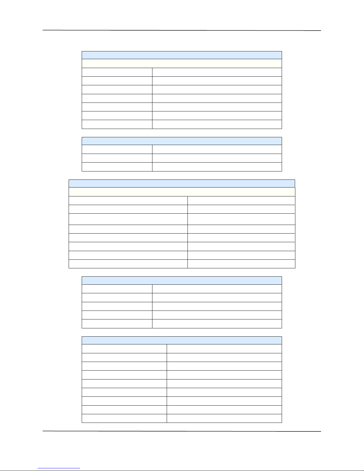
Table 3.1—General Specifications
Size (board) 100mm, 160 mm, 1.6mm (H, D, T)
(3.94 inch, 6.30 inch, 0.063 inch) (H, D, T)
Size (front panel) 3U x 4HP 128.7 mm, 20.32 mm (H, W)
(5.07 inch, 0.80 inch) (H, W)
Circuit Board Material UL 94V-0 FR-4
Power (TSAT-cPCI) +5V ± 5%: 425 mA max
+12V ± 5%: 425 mA max
–12V ± 5%: 50 mA max
Power (TPRO-cPCI) +5V ± 5%: 425 mA max
+12V ± 5%: 225 mA max
–12V ± 5%: 50 mA max
Operating Temperature TSAT-cPCI: 0 to 70 C (32 to 158 F)
TPRO-cPCI: 0 to 70 C (32 to 158 F)
Storage Temperature –40C to +85C (–40F to +185F)
Humidity 0 to 95%, non-condensing
TIMING Connector DB-15 socket, 15 pins
GPS ANTENNA Connector High-density, D-type plug, 15 pins
Table 3.2—CompactPCI®Interface
CompactPCI®Interface Standard 32-bit (J1 only)
CompactPCI®Spec 2.0 Compliant
Memory Map 64 consecutive 32-bit words (256 bytes)
I/O Map (None)
Chipset Vendor ID (PLX Technology, Inc.) 0x10b5
Chipset Device ID (PLX 9050 Chip) 0x9050
Subsystem Vendor ID (Spectracom) 0x1347
Subsystem Device ID (TPRO-cPCI) 0x7000
Subsystem Device ID (TSAT-cPCI) 0x7100
Table 3.3—On-board Clock
Synchronization to GPS (TSAT–cPCI) ±1 μS max
Synchronization to Time Code Input (TPRO-cPCI)
±10 μS max (IRIG-A)
±15 μS max (IRIG-B, NASA36)
Time base (freewheeling) TSAT-cPCI ±25 ppm (±25 μS per Sec)
Time base (freewheeling) TPRO-cPCI ±100 ppm (±100 μS per Sec)
Time base (freewheeling) TSAT-cPCI ±1 PPM in one minute
Time base (freewheeling) TPRO-cPCI–05 ±10 PPM in one minute
Range 366:23:59:59.999999
Resolution 1 μS

TPRO-cPCI/TSAT-cPCI Spectracom Corporation
Synchronizable Timecode Generator User Manual3-2
Table 3.4—External GPS Receiver/Antenna
TSAT-cPCI Only
Number of Satellites Tracked 12 max
Acquisition Time (Warm Start) 45 seconds (typical)
Acquisition Time (Cold Start) 2 minutes (typ), 15 minutes (max)
Frequency 1575.42 MHz (Receive Only, L1 Band, C/A Code, SPS)
Sync to UTC ±130 nS (1 sigma, stationary location)
Altitude –400 m to +8,000 m (–1,312 ft to +25,000 ft)
Position Accuracy 40 meters (135 ft) 2dRMS
Datum WGS-84
Operating Temperature –30C to +75C (–20F to +165F)
Storage Temperature –55C to +90C (–65F to +195F)
Humidity MIL STD 810E, Method 507.3, Procedure I, II, III (95%)
Weatherproof MIL STD 810E, Method 512.3
Salt Fog MIL STD 810E, Method 509.3 (48 hours)
Ultraviolet Protection ASTM G53-88
Transient Protection 600 Watts, 1 mS (data and power lines)
ESD IEC 1000-4-2 Level 4 (–8 KV to +8 KV)
EMI FCC Part 15 Class B, European CE
Size 115 mm, 90 mm (4.5 inch, 3.6 inch) (Diam., H)
Mass 475 g (16.8 oz.)
Mounting 1–14 UNS threads x 1 inch deep
Mating Connector Deutsch MMP26C-2212S1 Plug Housing
with Deutsch 6862-201-22278 Contact Sockets
Spectracom Corporation TPRO-cPCI/TSAT-cPCI
Synchronizable Timecode Generator User Manual 3
-
3
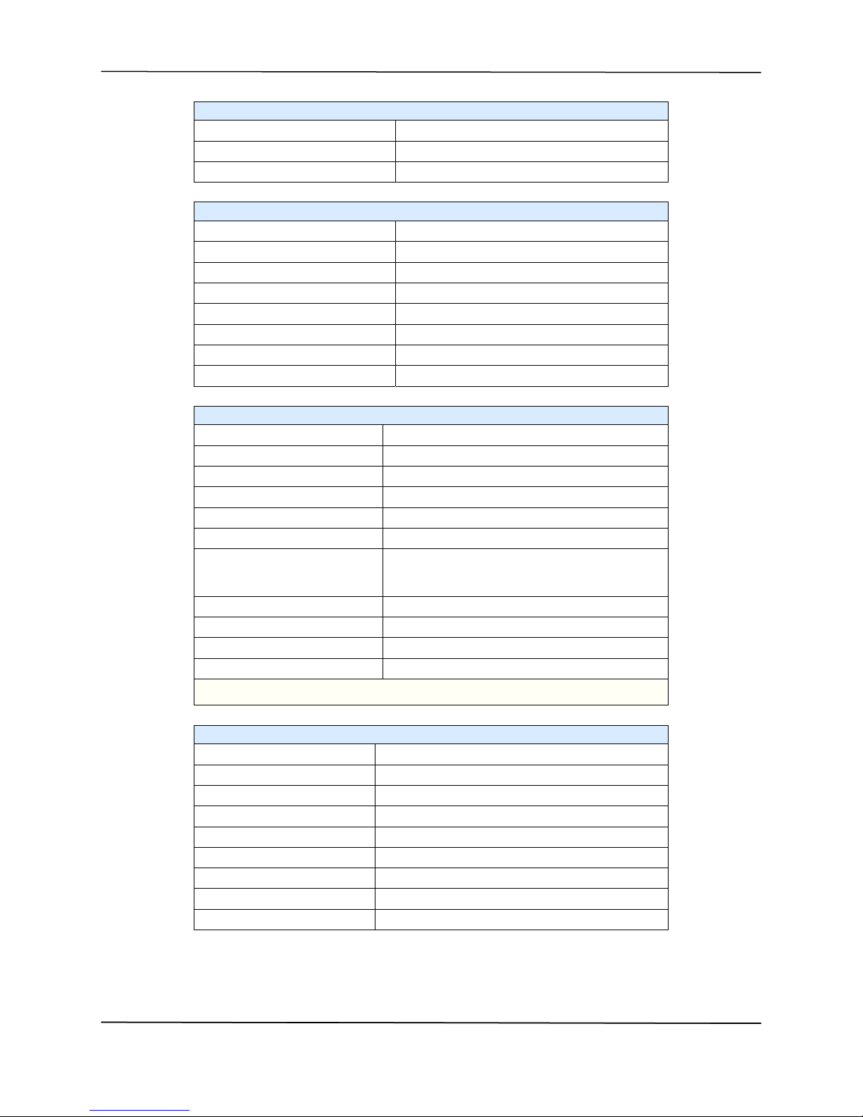
Table 3.5—Supplied GPS Antenna Cable
TSAT-cPCI Only
Length 30.5 m ± 0.3 m (100 ft ± 1 ft)
Cable Size 9 mm (0.4 inch) O.D.
Antenna Connector Size 20 mm (0.8 inch) O.D.
Board Connector Size 34 mm X 16 mm (1.4 inch x 0.6 inch)
Outer Jacket Black PVC with U/V Stabilizer/Inhibitor
Internal Wires 5 Twisted Pairs, 22 AWG, stranded, insulated wire
EMI Shield Foil (100% Coverage) and drain wire
Table 3.6—Optional Extension Cable for TSAT-cPCI
Length 30.3 m ± 0.3 m (99.5 ft ± 1 ft)
Cable Size 9 mm (0.4 inch) O.D.
Connector Size (both ends) 34 mm X 16 mm (1.4 inch x 0.6 inch)
Table 3.7—Time Code Input TPRO-cPCI Only
Connector DB-15 TIMING, Pins 1(+) and 2(–)
Format (detected automatically) IRIG-B(122) or IRIG-A(132)
Amplitude (mark) IRIG-A
Amplitude (mark) IRIG-B 1.2 Vp-p (min), 8.0 Vp-p (max)
1.2 Vp-p (min), 8.0 Vp-p (max)
Modulation Ratio 2:1 min, 3:1 typical, 4:1 max
Time Base Error ±25 ppm max
Input Impedance 10K ohm
Common-Mode Voltage (relative to signal ground) ±100 V max
Acquisition Time 15 seconds max
Table 3.8—Time Code Output
Connector DB-15 TIMING, pin 4
Format IRIG-B(122)(CF and SBS fields not used)
Amplitude (mark) 3.0 Vp-p min, 4.0 Vp-p typical, 6.5 Vp-p max; into 50 ohms
Modulation Ratio 3:1 (typical)
Time base Error same as specified for the on-board clock
Table 3.9—Time Tag Input
Connector DB-15 TIMING, pin 5
Tagged Edge Rising
Input Voltage (high) +2.2 V min, +5.1 V max
Input Voltage (low) –0.1 V min, +0.4 V max
Input Current (high) 100 uA max
Input Current (low) –600 uA max
Input Termination (on-board) 10.7K ohms to +5 Volts
Rise/Fall Time 150 nS max
Pulse Width (time high) 1 uS min, 999.999 mS max
TPRO-cPCI/TSAT-cPCI Spectracom Corporation
Synchronizable Timecode Generator User Manual3-4
Table 3.9—Time Tag Input
Time Between Each Rising Edge 500 uS min
Repetition Rate 2000 events/second max
Time Tag Accuracy ± 1 uS
Table 3.10—1PPS Output
Connector DB-15 TIMING, pins 13(+) and 12(–)
Output Type Differential RS-422
Recommended Termination 120 ohms, ½ watt, line-to-line
On-Time Edge Rising
Time base Error Same as on-board clock
Differential Output Voltage 3.0 Vp-p typical into 120 ohms
Output Skew (pin 13 to pin 12) 5 nS typical
Pulse Width 4 uS typical
Table 3.11—Oscillator Output
Connector DB-15 TIMING, pins 8(+) and 15(–)
Output Off, 1 kHz, 1 MHz, 5 MHz, or 10 MHz (programmable)
Power-on Default Frequency Off
Output Type Differential RS-422
Wave Shape Square wave, 40%/60% duty cycle
Recommended Termination 120 ohms, ½ Watt, line-to-line
Differential Output
(into 120 ohms)
2.5 Vp-p (1 kHz or 1 MHz)
2.0 Vp-p (5 MHz)
1.7 Vp-p (10 MHz)
Output Skew (pin 8 to pin 15) 5 nS typical
Cable Length* (1 kHz or 1 MHz) 76 m (250 ft) max
Cable Length* (5 MHz) 23 m (75 ft) max
Cable Length* (10 MHz) 3 m (10 ft) max
Spectracom recommends a 22 AWG twisted, shielded pair cable. Connect shield to
connector shell.
Table 3.12—Heartbeat Output
Connector DB-15 TIMING, pin 14
Wave Shape Pulse
Pulse Polarity Programmable
Pulse Width 100 nS, 333 nS, 1 uS, or 1 mS (Programmable)
Output Voltage (high) 2.4 V min at 2.5 mA
Output Voltage (low) 0.4 V max at –2.5 mA
Output Current (high or low) 2.5 mA max
Range 200 nS to 65.5 Seconds
Power-on Default Disabled
This manual suits for next models
1
Table of contents
Other Spectracom Inverter manuals


