Stearns 87,000 Series Quick guide

Installation and Service Instructions for
87,000; 87,100; 87,200; 87,400 and 87,600 Series
Important
Please read these instructions carefully before
installing, operating, or servicing your Stearns
brake. Failure to comply with these instructions
could cause injury to personnel and/or damage
to property if the brake is installed or operated
incorrectly. For definition of limited warranty/
liability, contact Rexnord Industries, LLC,
Stearns Division, 5150 International Dr.,
Cudahy, WI 53110, (414) 272-1100.
Caution
1. Installation and servicing must be made
in compliance with all local safety codes
including Occupational Safety and Health
Act (OSHA). All wiring and electrical
connections must comply with the National
Electric Code (NEC) and local electric
codes in effect.
2. Use of this brake in atmospheres
containing explosive gases and dusts
must be in accordance with NEC article
501. This brake is not suitable for use in
certain atmospheres containing explosive
gases and dusts. HazLoc inspection
authorities are responsible for verifying and
authorizing the use of suitably designed
and installed HazLoc equipment. When
questions arise consult local Authority
Having Jurisdiction (AHJ).
3. To prevent an electrical hazard, disconnect
power source before working on the brake.
If power disconnect point is out of sight,
lock disconnect in the off position and tag
to prevent accidental application of power.
4. Make certain power source conforms to
the requirements specified on the brake
nameplate.
5. Be careful when touching the exterior of an
operating brake. Allow sufficient time for
brake to cool before disassembly. Surfaces
may be hot enough to be painful or cause
injury.
6. Do not operate brake with housing
removed. All moving parts should be
guarded.
7. Installation and servicing should be
performed only by qualified personnel
familiar with the construction and operation
of the brake.
8. For proper performance and operation,
only genuine Stearns parts should be used
for repairs and replacements.
9. After usage, the brake interior will contain
burnt and degraded friction material
dust. This dust must be removed before
servicing or adjusting the brake.
DO NOT BLOW OFF DUST using an air
hose. It is important to avoid dispersing
dust into the air or inhaling it, as this may
be dangerous to your health.
a. Wear a filtered mask or a respirator
while removing dust from the inside of
a brake.
b. Use a vacuum cleaner or a soft brush
to remove dust from the brake. When
brushing, avoid causing the dust to
become airborne. Collect the dust in a
container, such as a bag, which can be
sealed off.
10. Do not run motor with the brake in
the manual release position to avoid
overheating of friction disc.
11. Do not lubricate any parts of the brake.
12. Do not adjust brake torque. The nominal
static torque is factory pre-set and should
not be altered.
General Description
The 87,X00 Series is a spring-set, electrically
released disc brake for controlled stopping and
holding of a load. It is self-adjusting for friction
disc wear and mounts directly to a NEMA
C-face motor with 8-1/2” (AK) register and a
7-1/4” (AJ) bolt circle.
The 87,100 Series Brake mounts to a
10-1/2” AK diameter register and 9” (AJ) bolt
circle.
The brake is provided with a manual release
lever or rod. When the motor is off and the load
is to be moved without energizing the motor,
the manual release lever or rod should be
used. This removes the holding torque from the
motor shaft, allowing it to be rotated by hand,
however drag may be noted. The brake will
remain in the manual release position until the
release lever or rod is returned manually to its
set position, or until the brake is re-energized
electrically and the release lever or rod returns
to its set position automatically.
Note: Fan-guard mounted brakes requiring
IP54 & IP55 protection may require additional
sealing measures beyond seals provided with
this brake. Pressurized sprays aimed at the
fan and brake hub surfaces can result in fluid
migration along the motor shaft and keyway,
and into the brake. The use of an appropriate
sealant such as RTV or a forsheda seal is
advised.
I. Installation Procedure - 87,000; 87,100;
87,400 and 87,600
A. Remove manual release knob (148) (on
pull type), housing nuts (15) and housing
(7). Housings equipped with side manual
release do not have release knob.
B. Depress solenoid plunger (29) and pull
release rod (146) back to lock brake
mechanism in manual release position or
wire tie plunger (29) to frame (79). The
87,600 Series Brake, brakes with optional
deadman manual release and brakes with
optional side manual release, the plunger
must be wire tied to the frame.
C. Remove entire support plate assembly
(142) by evenly unscrewing screw (142S).
Remove screws, conical spring washers,
and flat washers if supplied.
D. Remove pressure plate (5), friction disc (4),
and stationary disc (3).
Note 1: Brakes with a single friction disc do
not have stationary discs. Vertically mounted
brakes will have special pins which hold spacer
springs and, in some cases, spring washers
except one-disc vertical below. Note color
coded sequence of springs and location of
washers, if used, or refer to Instruction Sheet
P/N 8-078-937-05 (Sheet 301.3) for proper
assembly of vertical mounting components.
E. Attach endplate (2) to NEMA C-face of
motor using four 1/2” diameter socket
head cap screws (not supplied) torque per
manufacturer’s specifications. (Head of
cap screws must not project above friction
surface.) If foot mounted, secure foot
mounting bracket to foundation. The use
of dowels to insure permanent alignment
is recommended. Foot, machine or C-face
mounted brakes must be carefully aligned
within .004” on concentricity and face
runout. Shaft runout should be within .002”
T.I.R. Maximum permissible shaft endfloat
is .020”.
Note 2: If motor is to be ceiling mounted after
assembly, entire brake will have to be rotated
180° or “upside down” so it will be positioned
with solenoid plunger (29) above frame when
final assembly is mounted on ceiling. Similarly,
®Spring-Set Disc Brakes
P/N 8-078-927-00
effective 07/14/2017
Figure 1
2
150
16S
16
3
4
4
29
5
146
142S
7
15
148
Splined Configuration
16S16S
16B
16A 4B
4A
16 tooth 3.12 diameter 24 tooth 4.24 diameter

for horizontal wall mounting, rotate 90°.
Note 3: The brake nameplate states mounting
position; “horizontal, vertical above or vertical
below.” The brake must be mounted in that
position. Horizontal brakes rated 35 lb-ft and
less do not require modification to be mounted
vertical below.
Note 4: A dimple drilled into the motor shaft for
the hub set screw (16S), 90° from the key is
recommended for vertical mounting.
F. Position hub (16) and key (by customer)
on the motor shaft so outboard face of hub
will protrude approximately 1/32” to 1/16”
beyond face of last outboard friction disc.
(Position may be determined by assembling
friction disc(s) and stationary disc(s) onto
hub, noting hub position, and removing
disc(s).
Torque set screw (16S) as follows: 5/16
diameter - 13 ft-lb, 3/8 diameter - 24 ft-lb
and 1/2 diameter - 52 ft-lb. If brake utilizes
vertical mounting springs, do not assemble
them when measuring for hub location.
G. Reassemble friction disc (be sure friction
discs slide freely), spring (if vertical),
stationary discs, and pressure plate in
correct sequence and position. All parts
must slide freely. The universal mounting
pressure plate presently used has three
tapered reliefs on outboard face. However,
some older brakes used a pressure plate
with a single tapered
relief marked top, which must be installed
with relief facing manual release rod (146).
H. Mount support plate assembly, torque
screws to 50 in-lbs in endplate. Conical
spring washer installed under the screw
head. Flat washer used under the conical
spring washer only with aluminum support
plate. Be sure that assembly is mounted
with the solenoid in a vertical position
(plunger above frame) as shown when
brake is horizontal. If release rod (146) is
not in manual release position and has
allowed the mechanism to overadjust, it will
have to be reset before mounting support
plate. In this case, the lever arm (17) throat
will be near, or touching, the pinion (32)
teeth. Refer to Figure 6 and Self-Adjust
Maintenance. Loosen pressure spring cap
screw (19) until pressure spring (11) is free,
mount support plate assembly to endplate
and retighten spring cap screw until snug.
Do not overtighten! Torque to a maximum
of 8 ft-lbs.
I. Manually lift solenoid plunger to maximum
travel, and release. Complete electrical
connection. (See Section on Electrical
Connection of Brake.) Depress solenoid
plunger manually or electrically, and allow
it to snap up. Repeat this process several
times to set air gap on solenoid. (Check
Self-Adjust Maintenance Section for proper
gap measurement, or corrective action of
improper gap.)
J. Replace housing, nuts and manual release
knob.
II. Installation Procedure - 87,200 (See
Figure 1A)
As shown in the exploded view, Figure 1A,
the 87,200 Brake is very similar to the motor
mounted 87,000 Series. It is, however, a
self-supported, foot mounted unit, with an
integral bearing supported through-shaft. Since
disassembly is not required prior to mounting,
installation is simplified.
A. Bolt foot mounting bracket (34) to foundation
uses four 3/8-16 cap screws and lock
washers (not supplied). Torque cap screws
to 110 ft-lb specifications. Dowels are
recommended to maintain alignment.
B. For reference purposes, the endplate
mounting bolts, 1A, are torqued to 100-110
lb-ft for cast iron endplates; or 45-50 lb-ft for
aluminum endplates.
C. Do not exceed maximum overhung, or side
load ratings on output shafts. 100 lbs. on
housing end of brake, 150 lbs. on endplate/
foot stand end of brake. (Measured at 1”
from end of shaft).
D. See Section Electrical Connection of Brake.
Note:To remove housing for servicing of the
brake it is necessary to loosen the eccentric
bearing sleeve. Loosen the set screw on
the sleeve (35S) and, using a 3/16” drift pin,
rotate the sleeve on the shaft until loose
(about ±20°). Remove the housing nuts
(15) and release knob (148), and slide the
housing off the shaft. Reverse the procedure
for re-assembly.
III. Electrical Connection of Brake - All
Models
CAUTION 1: Inverter Motor and Special
Control Systems. This brake contains either
a single phase AC coil or DC coil that requires
instantaneous power within ± 10% of rating at
the coil. A separate power source is required
when this brake is used in conjunction with a
motor or control system that limits voltage or
current input (i.e. inverter motors) or causes a
ramping of the power supply.
CAUTION 2: Class H coils with terminals. Do
not bend lead wire crimp connection as this
causes a fatigue in the metal which may break
under vibration.
Note 1: Brake coil connections described
here cover common motor connections. For
nonstandard motor or control connections,
contact respective supplier or Stearns Div.
Note 2: Be sure lead wires to coil are not tight
or pinched, and that leads will not be rubbed
by friction disc, trapped between solenoid
plunger and frame, caught between lever arm
and endplate, or by linkage.
Note 3: On brakes with spacer heater, connect
to appropriate power source. Heater is to be
energized continuously, even during storage or
rusting may occur.
A. AC coils, single or dual voltage
1. Dual voltage coils may be factory precon-
nected for high voltage with wire nuts.
Checking coil connection is suggested. On
the 87,200 only, coil lead wire termination
is accessible at lead wire outlet of endplate
(2). Four lead style are marked on leads
for connection per Figure 4. Two unmarked
leads mean preconnection made for high
voltage. If reconnection of a dual voltage
coil is required (two unmarked leads) on the
87,200, housing (7) must first be removed
per Section and Figure 1A. Reconnect coil
for appropriate voltage as shown in Figure 4.
Bring out line leads.
2. On single voltage coils, connect coil to any
two leads on single or three-phase motors
of the same voltage as the brake. Refer to
brake nameplate and coil number for correct
voltage and frequency. See Figure 4 for dual
voltage coil connection and connect to any
two leads of single or three-phase motor of
the same voltage. The brake can also be
wired to external switch contacts providing
proper voltage other than that used to
control the motor. Normally, the motor and
brake contacts are interlocked.
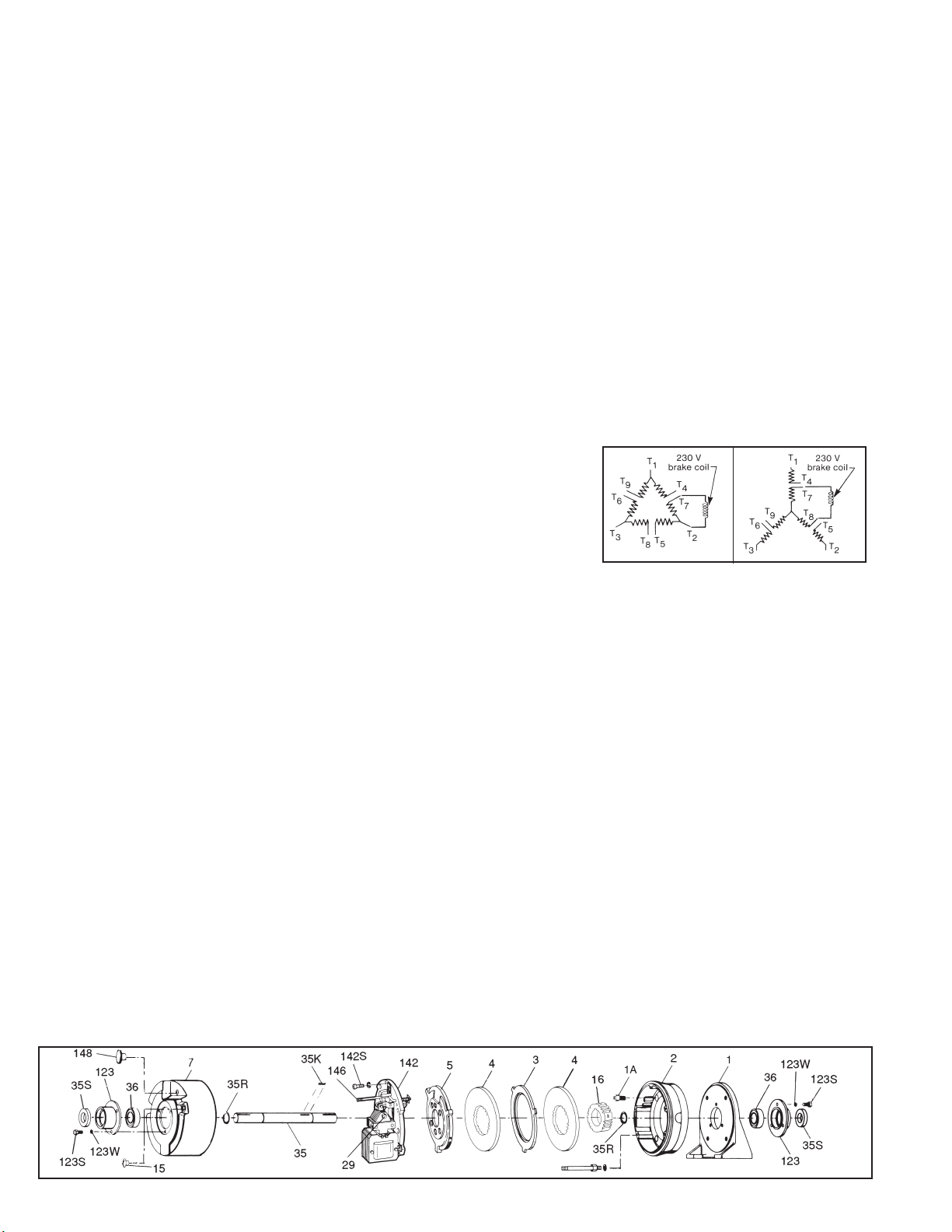
B. Connecting AC solenoid coils on dual
voltage 230/460 three-phase motors
To use a 230 volt coil (or a 230/460 dual
voltage coil connected for 230 volts) with a
230/460 dual voltage three-phase motor, the
brake leads are connected across two motor
terminals as shown in Figures 2 and 3 or other
equivalent combinations. If a 230 volt brake coil
is connected as shown in Figures 2 and 3 the
motor can be operated on either 230 volts or
460 volts with no effect on brake operation.
AC Voltage Coil Connection
C. DC coils - all models
1. All Stearns DC coils are single voltage
dual winding. A high current pull-in winding
is initially energized to start the plunger
movement, while a low current holding
winding is momentarily shunted from the
circuit until the plunger has pulled in. The
older design incorporated a mechanical
switch mounted to the solenoid frame and
actuated by an arm mounted to the plunger
to bring the holding winding into the circuit.
In addition, coils over 48 Vdc have an arc
suppression module in parallel with the
switch contacts to protect the contacts
from arc erosion and suppress EMI. The
polarity of the incoming power supply is
immaterial with the mechanical switch. The
new electronic switch design incor-porates
an electronic timing circuit to allow the
plunger to pull in, then electrically switch to
the holding winding. Polarity of the power
supply to the electronic switch and coil must
be maintained. Refer to Figure 5 for proper
wiring.
Caution! Never use a series resistor to drop
power supply voltage to the coil as brake
malfunction will result.
2. Due to high initial current demands of a
DC solenoid, a separate DC power source
Figure 1A
Figure 2 Figure 3

of adequate current capacity is usually
required.
Caution! For electrical release of brake, apply
full rated coil voltage instantly. Do not increase
voltage slowly.
IV. General Maintenance - All Models
Warning! Any mechanism or load held in
position by the brake should be secured to
prevent possible injury to personnel or damage
to equipment before any disassembly of the
brake is attempted or the manual release knob
or lever is operated on the brake. Observe all
cautions listed at the beginning of this manual.
Note 1: Replacement part kits for many items
are available and contain retrofit instructions.
Note 2: The 87,400 Maritime Series and
87,600 Navy Brakes as well as the 87,000
Marine Duty Brakes, though similar in
construction to the standard 87,000 Series
commercial brakes, utilize special materials
such as brass, bronze, ductile iron, etc. To
obtain correct replacement parts for the Series
87,000 Marine Duty or the Series 87,400 and
87,600 Brakes, obtain brake serial number and
consult factory.
A. Coil replacement - all models
All standard NEMA AC voltage coils are
available in kits. Select coil kit from appropriate
replacement parts list for the particular brake
series being serviced.
All standard NEMA DC voltage coils are
available in assemblies and may also be
obtained from appropriate parts list.
B. Friction disc replacement - all models
Note: Replace friction disc in single disc brakes
when wear surface area is one-half the original
disc thickness. In multiple disc brakes, replace
all friction discs when throat of lever arm (17) is
within 1/16” of touching teeth of pinion (32).
1. Observe cautions and warnings preceding
Installation Procedure, in Section I, Follow
Step A, then disconnect solenoid lead wires.
2. Continue with Steps B through D and Steps
G through J. Be sure to reconnect coil leads
before replacing housing (J).
C. Self-adjust maintenance (See Figure 6)
Since the self-adjust brake automatically
adjusts itself for friction disc wear, mainte-
nance is held to a minimum. The solenoid is
factory set with a 13/16” to 15/16” air gap, and
requires no resetting, even when changing
friction discs.
Measure air gap with brake fully assembled
without housing.
Note: To measure solenoid air gap on vertically
mounted brakes, grasp solenoid link to hold
plunger in a free horizontal position and move
toward solenoid frame until spring pressure
is felt. Holding firmly in this position, measure
air gap between mating (ground) surface on
solenoid frame and solenoid plunger. Adjust
to proper gap and check gap by again holding
plunger as directed.
The gap is determined by the position of wrap
spring stop (76). The normal operating gap is
13/16” to 15/16”. Should this change, follow the
steps listed:
1. If (stop) screws (76S) had been loosened
and retightened, the air gap may require
resetting. The gap is measured between
mating surfaces of plunger (2) and solenoid
frame (79), and may be increased by raising
slightly, or decreased by lowering slightly,
wrap spring stop (76). Be sure to retighten
(stop) screws (76S). Manually lift plunger
to maximum travel and release. Depress
plunger, manually or electrically, and allow
it to snap up. Repeat several times, then
recheck air gap. (For vertically mounted
brakes refer to Note in Section IV under Item
C).
2. Tang of wrap spring (71) must be below, and
must make contact with, wrap spring stop
(76) when solenoid lever (28) is manually
raised. If stop is bent outward, allowing
tang to bypass it, rebend to square position,
assemble correctly, and reset solenoid air
gap as described in Paragraph 1.
3. Should air gap disappear due to
overheating, oil or other lubricant may
have been applied to solenoid lever and
pinion assembly (8). Remove support plate
assembly (142). Loosen pressure spring
nut (19) until pressure spring (11) is free.
Remove cotter pin (8P) from solenoid lever
(28) and retaining ring (131R) from pivot
pin (131). Note location of spacer washer
(138) if used, and push pivot pin out to free
affected assembly. Remove retaining ring
(32R) from pinion (32) and disassemble.
Parts should be thoroughly cleaned in
M.E.K. or equivalent
solvent that does not
leave a film. Dry all
parts thoroughly and
reassemble. Rotate
pinion and wrap spring
clockwise until tang (A)
is aligned with centerline
of the upper hole of
the lever arm. Refer to
Figure 7. Reassemble
in reverse order. Do
not retighten cap screw
(19) until support plate
assembly is mounted on endplate. Refer to
Steps H and I of Installation Procedure to
complete assembly.
4. Check condition and positioning of pinion
(32) and rack (part of lever arm assembly,
17). Replace parts as necessary with com-
plete assemblies. See following Sections.
D. Solenoid lever and pinion assembly
replacement - all models except
Series 87,600
If pinion (32) teeth are worn, replace entire
assembly (8). Consult appropriate parts list for
kit number. Check sector gear of lever arm (17)
for wear.
E. Lever arm replacement - Series 87,000;
87,100 and 87,200 only
If sector gear teeth of lever arm (17) are worn,
replace entire lever arm assembly available
as a kit from appropriate repair parts list. Also
check pinion (32) teeth for wear. See Item
8. Do not attempt to use this aluminum lever
arm with Series 87,400 (Maritime) and Series
87,600 (Navy) Brakes.
F. Pressure spring stud and nut
replacement - Series 87,000; 87,100; 87,200
and 87,400
On older designs of above brakes, Item (152)
was threaded shoulder stud, Item (152P) was
a solid pin. These items have been replaced
by a spring tube, cap screw and spring pin.
Replacement of any individual component
requires replacement of all three older style
components. Consult appropriate repair parts
list for complete retrofit kit. The 87,600 (Navy)
Brake uses the pressure spring stud and nut
arrangement. Consult appropriate master plan
drawing for piece part numbers.
V. Troubleshooting
A. If brake does not stop properly or
overheats, check the following:
1. Is manual release engaged, and is motor
energized?
2. Friction discs may be excessively worn,
charred or broken.
3. Hub may have become loose and shifted
Figure 4
3 and 421High voltage –2 and 41 and 3Low voltage Tie Leads
Power Line BPower Line A
For
Class H Coil (colored) Class B Coil (black)
DC Voltage Coil Connection
Figure 5
*Arc suppression used for coil above 48 Vdc.
**Follow polarity for switch to operate.
Electronic Switch** (New Style)
Mechanical Switch (Old Style)
Class BClass H
Figure 6
Figure 7

on shaft.
4. Is hub clean and do friction discs slide
freely.
5. Are controls which govern start of braking
cycles operating properly?
6. Are limit switches, electric eyes, etc.
functioning properly?
7. On vertically mounted brakes, are springs
in place of disc pack? See
P/N 8-078-937-05 (Sheet 301.3).
8. If brake is floor mounted, check alignment.
See Section I, Step E.
9. Pressure spring may be improperly
assembled or broken.
10. Is solenoid air gap adjusted correctly? See
Self-Adjust Maintenance, Section IV, Item
C.
11. Check linkage for binding. The approximate
pressure applied to the top of the solenoid
link to move plunger is:
If excessive force is required, determine
cause of binding and correct. Do not
overlook bent, worn or broken plunger
guides as a possible cause for binding.
12. Solenoid lever stop (22) must be in place
on support plate.
13. Solenoid may not be energizing and
releasing the brake. Check voltage at
the coil and compare to the coil and/or
nameplate voltage rating.
14. Whether brake is AC or DC a voltage drop
may be occurring. If excessive drop in
voltage is noted, check wire size of power
source. Correct as needed.
Note: A method to check voltage at coil is
to insert a block of wood of the approximate
thickness of the solenoid air gap between
the solenoid frame and plunger. (The block
will prevent brake from releasing when coil
is energized.) Connect voltmeter leads at
the coil terminals or lead wires. Energize
coil. Voltmeter needle will not fluctuate and
reading can be taken. Reading should be
taken immediately and the coil de-energized
to prevent overheating of the coil. Compare
voltage reading with coil rating.
15. If brake is DC solenoid style, check switch
actuation and condition of coil. The switch
should open with the following approximate
air gap. (This is plunger travel remaining
before plunger seats to frame.) Solenoid
size is used for reference:
If actuating arm is bent, replace plunger.
Check switch contacts. If pitted, replace
switch.
16. Check slots of endplate for wear at the
areas where stationary discs are in contact.
Grooves in the slots can cause hang-up or
even breakage of ears of stationary discs.
If grooving is noted, replace endplate.
17. Check that heads of mounting bolts do not
extend above wear surface of endplate.
18. On vertical brakes with cast iron end-
plates, check the vertical mounting pins
to be sure shoulder of pin is flush with
wear surface of endplate. Be sure pins are
straight and pressure plate and stationary
disc(s) are free to slide on the pins. Be
sure springs and spacers are installed in
proper order. See P/N 8-078-937-05
(Sheet 301.3).
19. Check pressure spring length to insure
correct compressed height. Original spring
lengths are given in the following Table
so that correct setting may be verified
and corrected if necessary. With worn
friction discs, add amount of wear to the
approximate spring length shown.
20. If a heater is supplied and excess rusting
has occurred in brake, check power source
to heater to be sure it is operating and that
heater is not burned out.
21. If stopping time is more than two seconds
(rule of thumb), the brake torque rating
may be insufficient. If the brake stops high
inertial loads and/or brake stops more
than five times per minute, check thermal
requirements of application versus thermal
capacity rating of brake.
22. Use Loctite® 242 to secure link screw
nut (13N) to link screw (13C) if vibration
causes nut to loosen.
B. If brake hums, solenoid pulls in slowly,
or coil burns out, check the following:
1. Voltage supply at coil versus coil rating.
2. Is solenoid air gap excessive? See Self-
Adjust Maintenance.
3. Shading coils may be broken.
4. Plunger guides may be excessively worn.
Does solenoid plunger rub on solenoid frame
laminations? If so, replace plunger guides.
5. Solenoid frame and plunger may be
excessively worn.
6. Is solenoid dirty?
7. Solenoid mounting screws may have
become loose, causing frame to shift and
plunger to seat improperly.
8. Sector gear and pinion teeth may be
jamming due to excessive tooth wear.
9. Excessive voltage drop when motor starts.
Check size of lead wires for motor starting
current and solenoid inrush current. See
Section V-A, Items 11, 12, 14 and 15.
C. If brake is noisy during stopping:
1. Check mounting face runout, mounting
rabbet eccentricity and shaft runout. See
Installation Procedure, Section I, Step E.
Correct as required.
2. Check for signs of the outside diameter
of the friction disc(s) rubbing on the inside
diameter of the endplate. This would indicate
brake is eccentric with respect to the motor
shaft and/or the shaft is deflecting during a
stop. Check alignment and shaft diameter.
Also check for worn motor bearings. If
realignment does not correct the problem, a
larger diameter shaft may be required. Shaft
deflection may also be caused by excessive
overhang of brake from motor bearing.
Additional shaft support may be required.
3. In cases where motor shaft extends through
a fan casing or guard, the clearance hole
may not be adequate. Rubbing of the shaft
may occur causing a noise during a stop. If
required, enlarge clearance hole.
4. Check for bad motor bearings. Replace
if necessary. Check for excessive shaft
endfloat. Correct as required.
7/32” to 1/4”#6 solenoid
3/16” to 7/32”#5 or #8 solenoid
3-1/4”35, 75 & 105Purple 3-1/4”25 & 50Orange 3-1/4”15White 3-1/4”10Black 3-3/8”35, 75 & 105Green 3-3/8”25 & 50Red 3-9/16”15Yellow 3-5/16”10Blue
Compressed
Spring Length
Torque
(lb-ft)
Color
Copyright© 2000-2017 by Rexnord Corporation
Rexnord Corporation, Stearns Division, 5150 International Dr., Cudahy, Wisconsin 53110, (414) 272-1100 Fax: (414) 277-4364 www.rexnord.com/stearns
16 lbs#8 coil 9 lbs#6 coil (25 lb-ft) 5-1/2 lbs#6 coil (15 lb-ft) 3 lbs#5 coil
This manual suits for next models
4
Other Stearns Industrial Equipment manuals
Popular Industrial Equipment manuals by other brands

Leroy-Somer
Leroy-Somer Nidec LSAH 42.3 Installation and Maintenance

Mod-U-Blast
Mod-U-Blast MBM Series owner's manual

Zodiac
Zodiac Heat Line 20 Instructions for installation and use

Panasonic
Panasonic Aicure UD40 Series user manual

SUHNER ABRASIVE
SUHNER ABRASIVE UAK 30-RF SPZ-L Technical document

Clarke
Clarke C18H instruction manual