Steel Core 40809 User manual

*Actual product may vary slightly
Please carefully read and save these instructions before attempting to assemble, maintain, install, or operate this product.
Observe all safety information to protect yourself and others. Failure to observe the instructions may result in property
damage and/or personal injury. Please keep instructions for future reference.
For warranty purchases, please keep your dated proof of purchase. File or attach to the manual for safe keeping.
For Customer Service, Call 1-800-348-5004
This product contains or, when used, produces a chemical
known to the State of California to cause cancer and birth
defects or other reproductive harm.
(California Health & Safety Code § 25249.5, et seq.)
WARNING
11GA COIL ROOFING NAILER
40809
Z87
Fig.1
Fig.2
Fig.3
BC
A
WARNING: W hen using pneumatic tools, basic safety precautions
should always be followed to reduce the risk of personal injury,
There are certain applications for which this to ol was designed. we
strongly recommends that this tool NOT be modified and /or used for
any application other than for which it was designed. If you have any
questions relative to its application, please contact with our dealer.
including the followin g:
READ AND F OLLOW ALL INS TRUCTIONS.
IMPORTANT SAFETY INSTRUCTIONS
1. KEEP WORKING AREA CLEAN.
2. DON'T ALLOW CHILDREN KEEP AT
THE WORKING AREA.
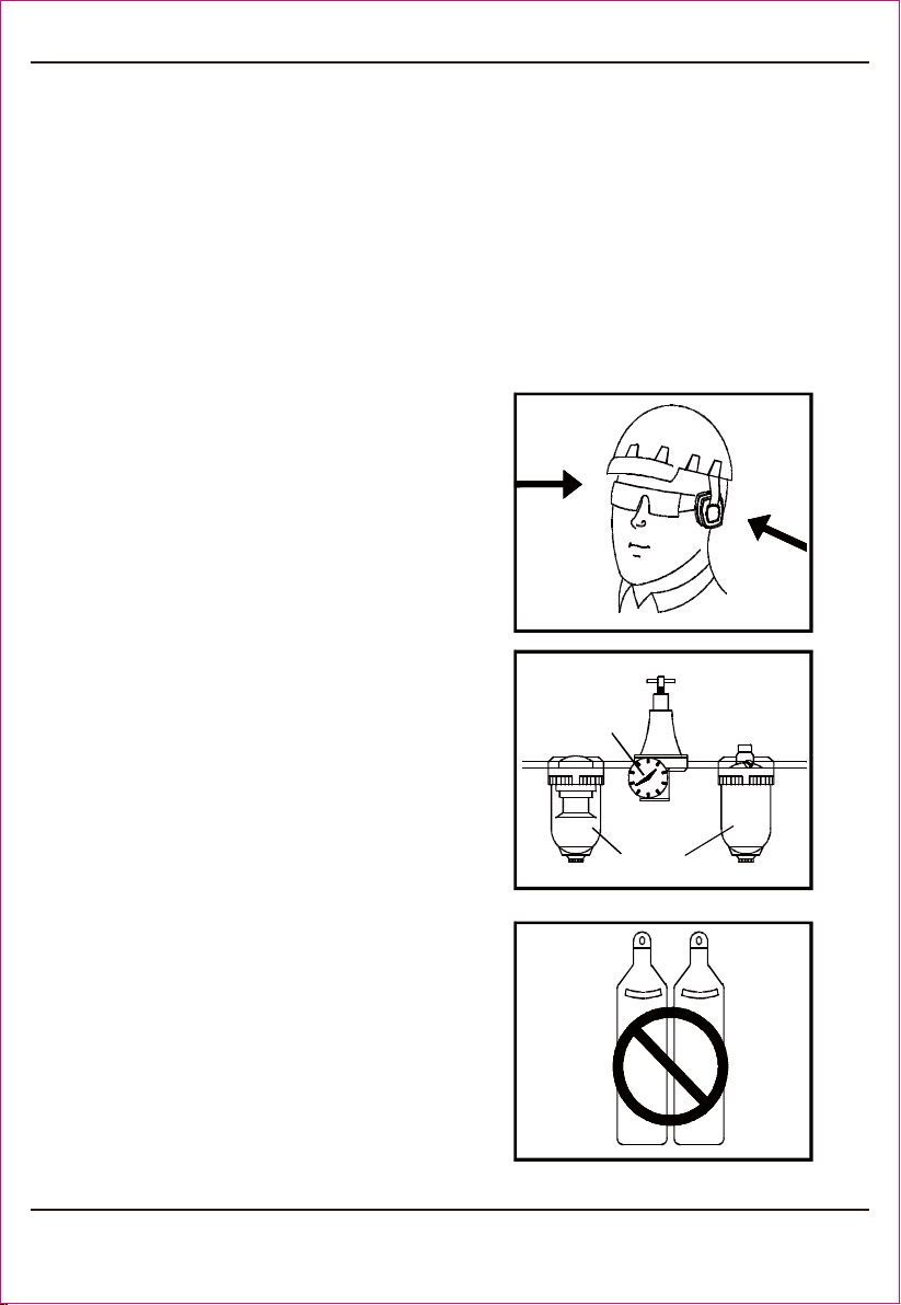
3. USE SAFETY GLASSES.
4 . U S E E A R PRO T E CT I ON .
5. DRESS SAFELY.
6. O NLY U SE CL EAN , D RY AND
REGULATED
C l u t t e r e d a r e a s i n v i t e i n j u r i e s .
Don't let them
To prevent
eye injuries, the tool operator and all
persons in the working area must wear
s a f e t y g l a s s e s w i t h p e r m a n e n t l y
attac hed, rigid, plastic side shields.
These safety gla sses must conform to
ANSI Z87.1 requirements (approved
glasses have “Z87” printed o r stamped
T he
working area may be exposed to high
noise levels that can lead to hearing
Protective gloves
and nonskid footwear or safety shoes
are recommended when working with
and operating this tool. Don't wear loose
clothing or jewelr y. They can get caught
in moving parts. Also, wear a protective
hair covering to prevent long hair from
compressed a ir at 70 to
handle the tool.
on them).
damaged.
getting caught in the tool.
120 PSI (4.8 t o 8. 3 BA R) .

Fig.4
Fig.6
1
2
3
Fig.5
7. NEVER USEOXYGEN, CARBON
DIOXIDE,
8.DO NOT CONNECT TOOL
9. ONLY US E AIR HOSETHAT IS
RATED
10.DON'T OPERATE TOOL NEAR THE
COMBU ST IB LE ,
11 DISCONNECT TOOL FROM AIR
S U PPLY H OSE
12.O N L Y D I SCO N N ECT Q U I C K
CON N EC TOR B E IN G C ONNE C TED
13.REPLACE PARTS AND ACCESSO-
R I ES.
combustible gases or any
otherbottled gas asapower source for
to pressure
thatpotentially exceeds180PSI(12.3
for 150% o f the m aximu m
systempressure.
.
or a ny o th er easy
explosive material and don't operate the
tool under easy producing corrosion,
r u s t and h a v i n g h e a v y p o w d e r
.
before doi n g t o o l
m a i n t enanc e , c l e a r i n gaj a m m e d
fastener, leaving work area, moving tool
to another location, or handing the tool
with the connector of the body tail
portion air inlet, no compressed air can
be guaranteed when disconnecting. If
operating is not correct, thetool can
remain charged with air afterbeing
disconnected and still be able to drive a
Onlyallo w u s e s a m e
rep la cem e nt p arts w hile s erv ic i ng.
Approved accessories andreplacement
Please try to useahose
o f I D 3/8”conn e c t i n g nai l e r w i t h
this tool.
BAR).
environment.
to another person.
parts are available.
fastener, causing personal injury.
Compressor.
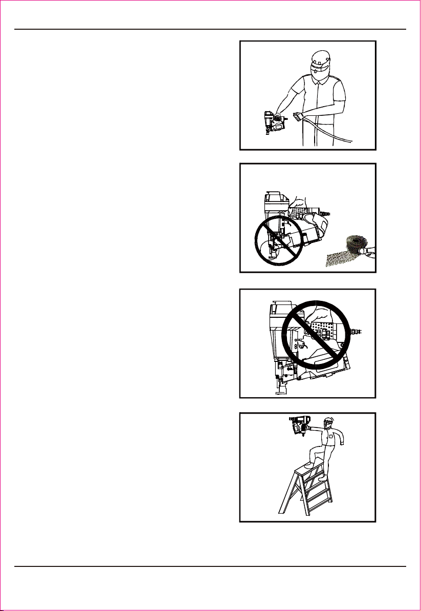
Fig.10
Fig.9
Fig.8
Fig.7
14. BEFORE USING TOLL,
15. NEVER USE TOOL
1 6 . O N L Y U S E P A R T S A N D
FASTEN ERS,
17. CONNECT TOOL TO AIR SUPP LY
BEFORE
1 8 .A LWAYS A S S UM E T HE TO O L
C ONTAI NS FA STENE RS.
19. DO NO T LOAD FASTENERS
20. REMOVE FINGER FROM TRIGGER
21. DON'T OVER REACH .
carefully
check if there is any part damaged to
obt ain ideal results. Do not use the tool
i f th e t o o l h a s a n y a ir le a k e d ,
uncompleted, damaged par ts and n eed s
if safety, trigge r
o r s pr in g i s i no per ab le , missin g o r
damaged. Do not alter or remove safety,
t ri g g e r o r s p r i n g s . M a k e d a i l y
inspe ctions f or f re e movement of trigge r
re commende d by us .
loading fasteners, to prevent a
f a s t e n e r f r o m bei n g f i re d du r i n g
connection. The tool dri ving mechanism
may cycle whe n tool is connected to the
air supply. Wh en not in use remove all
Keep the tool
poi nted awa y from yourself and others
at all times. No hor seplay. Respect the
with
trigger or safe ty depressed, to prevent
u n in te nt io nal f ir i n g o f a f as ten e r.
when not drivi ng fasteners. Never carr y
tool with finger on tr igger: tool will fire a
faste ner if sa fe ty is b umpe d whi le trigge r
Keep prope r
footing and balance at all times when
22. FIRE FASTENERS INTO WORK
SURFACE ONLY: NEVER into materials
repairing.
and safety me chanism .
fasteners from the nail housing.
tool as a working implement.
is depressed.
using or handing the tool.
too hard to penetra te.
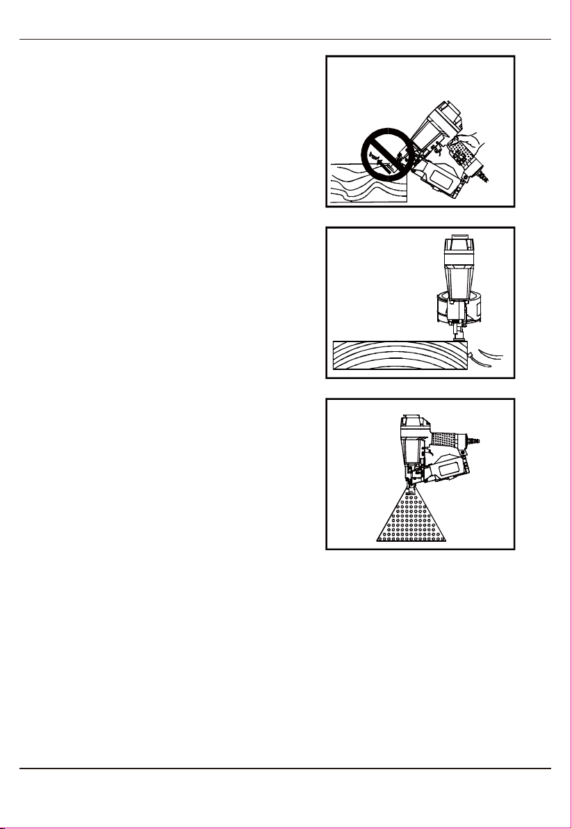
Fig.13
Fig.11
Fig.12
23. GRI P TOOL FIR MLY TO MAINTAI N
CONTR OL
24. DO NOT DRIVE FASTENERS
2 5 . D O N O T DR IVE FA S T E N ER S
CLOSE
26. KEEP ALERT.
27. KEEP HANDS AND BODY PARTS
28. T HIS TOOL IS EQU IPED W IT H
AD JU S TER
29. WHEN NOT IN USE,
while allowing tool to recoil
away from work surface as fast ener is
driven. If safety bracket is allowed to
co nta ct wor k su rf ace agai n b ef or e
t ri gger i s re l e a s ed, a n un w a n t ed
on
top of other fasteners, o r with the tool at
too steep an an gle: the fasteners can
to the edge of the workpiece.
The work piece is likel y to split allowing
the fastener to fly free or ricochet
Watch what you are
doing. Use common sense. Do not
operate any tool when you are tired.
away from area shown in Fig. 13, to
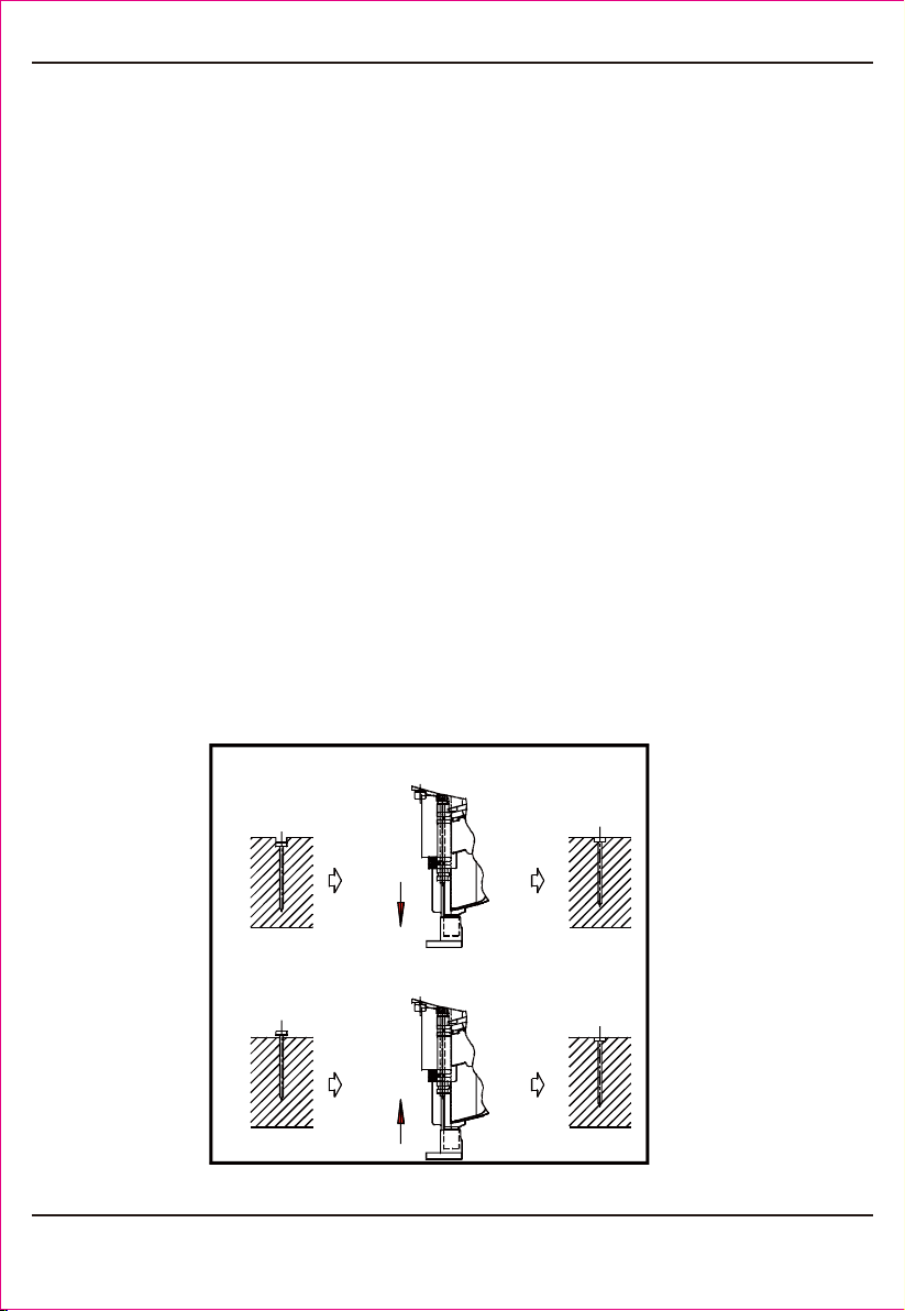
that ca n ad ju st dri vi ng
depth. When adjusting the driving depth,
first disconnect from air supply, rota te
the knob of the adjuster by hand until it
tool should be
cleaned and put it back into the packing
box. For safety, ke ep out of reach of
children.
fastener will be fired.
ricochet causing persona l injury.
causing personal injury.
avoid injury.
is satisfactoy.
Employer m ust enforce compliance with the safety warningsand all
Keep this manual available for use by all people assigned to use this
For personal safety and properoperation of this tool, read and follow all
EMPLOYER’S RESPONSIBILITIES
other instructions contained in this manual.
tool.
of these instructions carefully.

1-800-348-5004
DESCRIPTION
Roofing coil nailer
S5 Hex Key
S4 Hex Key
S3 Hex Key
Air Tool Oil
Safety glasses
Operating instruction
Q'ty
1
1
1
1
1
1
1
PACKING LIST
TECHNICAL PARAMETER
CHARACTERISTIC
Compressed Air pressure
Outline Dimension (L H W)
Nail Length Range
Too l Weight
Air Inlet
Air Consumption
× ×
VALUE
70-120PSI (4.9-8.3bar)
11.5 "
/ "-1 /
5
1/4 NPT
0.11ft /cycle at 100psi(at pressure
6.9bar, 3.1 litre/ cycle)
" 11.5 5"
"
"
× ×
7 3
3
8 4
.58 Ibs (2. 53K g)
1-800-348-5004
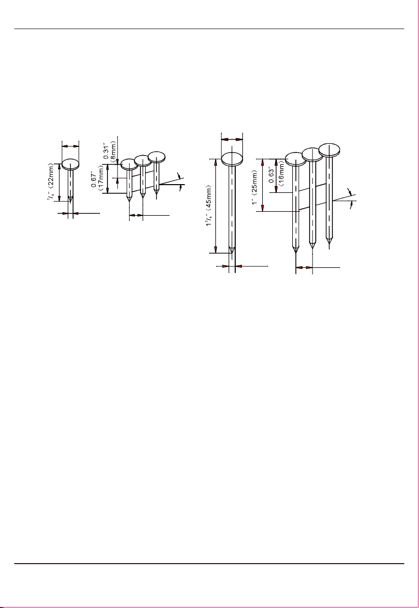
FASTENERS SPECIFICATIONS
Only use recommended the fasteners.
OPERATING INSTRUCTIONS
FOREWORD
POWER SOURCE
It’s a he avy duty, coil fed, pneumatic roofing nailer, u sing
compressed air as power source. It is designed to install / ˝-1 / ˝or
0.12˝diameter roofing nails of various lengths. It is widely used for
connection of roofing frame and connection of roofing frame and felt.
This tool is designed to operate on clean, dry, compressed air at
regulated pressures between 70 and120 PSI (Pounds per Square Inch).
The preferred system w ould include a filter (C) Fig.2, a pressure
regulator (A) Fig.2, andautomatic oiler (B) Fig.2 located as close to the
tool as possible (within15 feet is ideal).
All compressed air contains moisture and other contaminates that a re
detrimental to internal components of the tool. An air-line filter will
remove most of these contaminates and significan tly p rolong the life of
the tool. I f an in-line oiler is not available: place five or six drops of oil,
into the tool’s air inlet at the beginning of each workday.
Only disconnect quick connector being connected with the connector of
the body tail portion air inlet, no compressed air can be guaranteed
when disconnecting.
7 3
8 4
Ø
Min.
0.39φ˝
( )φ10mm
3.05mmφ( )
0.12φ˝0.31˝
( )8mm
15 -16
o o
Max.
0.39φ˝
( )φ10mm
15 -16
o o
3.05mmφ( )
0.12φ˝0.31˝
( )8mm

1-800-348-5004
PREPARING THE TOOL BEFORE DRIVING
CAUTION:
1. After reading and unders tanding this entire manual, connect tool to
air supply.
Keep tool pointed away from yourself and others at all
times.
Always conne ct tool to air supply before loading fasteners.
Do not load fasteners w ith trigger or safety depressed.
Always we ar Z87 approved safety glas ses, and he aring protection
when preparing or operating the tool.
Never use a tool that leaks air or needs repair.
2. Depress HANDLE (See A Fig. 14 ) and open t he LATC H. R otate the
UPPE R NAIL HOUSING to the side of the BODY.
3. The ADJUSTER PLATE can be move d up and down when twisting the
ADJUSTE R NUT(see B Fig.15) . According to the length of nail, the
ADJUSTE R PLATE should be adjusted correctly to t he position
Indicated inside LO WER NAIL HOUSING.
4. Place a coil of nails over the LOWER NAIL HOUSING . Uncoil enough
nails to reach the F EED HO OK and place the second nail betwee n the
teeth on the FE ED HOOK. (see Fig. 16).
5. Close the UPPER NAIL HOUSING and depress the LATCH (see Fig.
17).
6. Adjust directional EXHAUST deflector (s ee F ig. 18), so that the
exhaust air blast will be directed aw ay from the operator. Grasp the
deflector and rotate it to the desired position for the current application.
CAUT ION : All line co mponents (ho ses, co nnectors, filters,
regulators, etc.) must meet 150% of the maximum system pressure.
Please try to useahose of ID 3/8”connectingnailer with compressor.
Do not connect this tool to a system with maximum potential. Only
disconnect quick connector being connected with the connector of
the body tail portion air inlet, no compressed air can be guaranteed
Disconnect tool from air supply before performing maintenance,
clearingajammed fastener, leaving work area, moving tool to
when disconne cting .
ano ther location, or handing the tool to another person.

1-800-348-5004
Fig.16
Fig.14
A
Fig .15
B
Fig .17
Fig.18
A
Fig.19
A
USING THE TOOL
There are two methods of operation to drive nails with theis
tool: Contact Fire and Single Sequential Fire (Black trigger)
Contact Fire
This tool is set up at the Contact Fire mode
1. P ull the trigger with th e tool off the work piece
2. Depress the safety ag ainst the work piece to drive a nail
3. Move the tool along the work piece with a boun cing motion. Each
depression of the safety w ill drive a nail. As soon as the desired number
of nails has been driven, remove your finger from the trigge r.
1-800-348-5004
Single Sequential Fire
1. Position the nail outlet on the work piece with finger off the trigger
2. Depres s the safety firmly until it is comple tely depressed.
3. Pull the trigger to drive a nail
4. Remove finger from the trigger.
To continue nailing in a separate location, move the tool along the
wood, repeating steps 2 - 4 as required.
Remove finger from trigger whe n not driving fasteners.
Never carry tool with finger on trigger: tool will fire a fastener if
safety is bumped.
Keep tool pointed in a safe direction at all times.
Never attempt to drive a fastener into material that is to o hard, or at
too steep an a ngle, or near the edge of the workpiece. The fastener
can ricochet causing personal injury.
Disco nnect tool from air supply before performing maintenance,
clearing a jammed fastener, leaving working area, moving tool to
another locatio n, or handing the tool to another person.
Clean and inspect tool daily. Carefully chec k for proper operation of
trigge r and safety mechanism. Do not use the tool unless both the
trigger and the safety mechanism are functional, or if the tool is
leaking air or needs any other repair.
3. Driving depth will be adjusted by adjusting adjuster (A) Fig.19 .
Test fire a fastener an d check depth. If the nail is driven too deep,
rotate the adjuster to ma ke safe bracket do wnw ard. Whereas,
CAUTION:
Fig.20

1-800-348-5004
Fig.21
1. Disconnect tool from air
2.Open latch, rotate lower housing and
remove the nails of the lowe r housing.
3.Use a slender, soft steel rod to drive the
drive blad e to its uppermost position. U se
needle nose pliers to remove the jammed
CAUTION:
fastener (see Fig.21).
supply .
4.Follow instructions in PREPARING THE TOO L BEFORE DRIVING to
reload fa steners.
CLEARING A JAMMED
FASTENER
Disconnect tool from air supply before cleaning and
Ad d pneumatic tool oil into the oiler regularly to remain the moving
components of the tool fine lubrication. Check the filter of the
compressor weekly and s witch off manual valve to drain water and
Wipe the tool clean. Blow the tool clean by high compressed air, then
use non-flammable cleaning solutions to wipe exterior of tool only if
necessary. Do not soak tool with cleaning solutions. Su ch solutions can
damage internal parts. The expose d portion of the small piston rod and
Inspect triggerand safety mechanism to assure system is complet e and
functional: no loose or missing parts, no binding or sticking parts shall
Ke ep all screws tight. Loose screws can cause personal injury or
Check if there are worn and damaged parts. If any, please repl ace
If tool is used without an in -line oiler: place 5 or 6 drops of porter-cable
air tool oil into the air inlet of the tool at the beginni ng of each workday.
CAUTION:
MAINTENANCE
CLEAN AND INSPECT DAILY
inspection. Correct all problems before operating.
contaminations out.
feed hook must be kept clean.
be found.
dama ge t ool.
immediately.

1-800-348-5004
TROUBLE SHOOTING
CAUTION: Disconnect tool from air supply before performing
any Service Procedure.
PROB LEM
CA USE
SOLUTION
Air le aking at trigger area
1. O-ring in trigger valve stem
is worn and damaged.
2. O-ring in trigger valve head is
worn and damaged.
3. Having foreign matters.
1.Che ck/re placeO -ring/lubricate.
2.Che ck/re placeO -ring/lubricate
3.Clean the tool/lubricate
Air leaking at the body
lower portion and nose
1.Screw is loose at connecting
portion of the nose and body.
2.O-ring is damaged between
body and nose.
3.Bumper is damaged.
4.Having the foreign matters at the
contacting portion of t he bumper
and body.
1.Tighten screw/recheck
2.Che ck/re placeO -ring/lubricate
3. Replace the bump er.
4. Disasse mble an d clean
Air leaking a t the body
upper portion and nose
1.Screw is loose at the connecting
portion of the cylinder and body.
2.O-ring is damaged.
3.Gasket is damaged.
1. Tig hten t he screw and recheck.
2. Check/replace0-ring/lubricate
3. Replace the gasket.
Failure to start tool.
1.Tool dry, lack lubrication.
2.The spring in the cylinder cap is
damaged.
1. Use pneu matic too l oi l
2.Replace the spring in the
cylinder cap.
Blade driving fasteners
too deeply
1.Safe bracket poison is not
correct.
2.Air pressure is too high.
1.Rotate knob of the adjuster to
move safe bracket down.
2.Decrease air pressure.
All quality tools eventually require servicing of rep lacement of parts due
to wear from normal use. Some user servicea ble components are
described in the TROUBLE SHOOTING Section. All repairs made by
local agencies are fully guaranteed against defective material and
workmanship. We cannot guarantee repairs made or attempted b y
Should your have any questions about your tool, please contact with us
at any time. In any communications, please give all information shown
on the nameplate of your tool (model number, type , serial number, etc.)
SERVICE AND REPAIRS
anyone other than these ag encies.

1-800-348-5004
Skippin g
fastene rs/feeding
intermittently
1.Having the foreign matters
between the small piston and
small cylinder.
2.O-ring on the small piston is
worn and damaged.
3.Tool dry and lack lubrication.
4.The spring on the small piston is
damaged.
5.Air pressure is lower.
6.Connecting screw of nose and
body is loose.
7.Stopped hook ca n't stop the
fasteners.
8.Bent fasteners.
9.Wrong size fasteners.
10.Gasket is damaged.
11.Small piston bumper is worm
and damaged.
12.Feed hook is binding.
13.Nail length is not correct with
loading space of nail housing.
14.Weld wires in nail coil is broken.
1.Disassemble/ clean/lubricate.
2.Che ck/replaceO-ring/lubricate
3.Use pneumatic tool oil.
4.Rep lace small piston the spring.
5.Increase the air pressure, but
don't exceed 120 PSI (8.3 bar).
6.Tighten all screw.
7.Rep lace taper spring of the
stopped hook.
8.Use recommende d fasteners.
9.Use recommende d fasteners
10.Re place gasket/tighten screw.
11.Replace bumperand lubricate
small piston.
13.Clean feed hookand torsion
spring.
13.Adjust adjuster plate at the nail
housing tail portion according to
the recommended nail length to
make arrow on the nail housing
tail pointing to correct direction.
14.Stop using.
PROBLEM
CAUSE
SOLUT ION
Ru ns slowly or has power
loss
1. Tool dry, lack lubrication
2. The spring in the cylinder cap is
damaged.
3.Having foreign ma tters between
piston assembly andcylinder.
4.Have not assembled the cylinder
to home position.
5.O-ring on the valve is dry after
disassemble.
6.Air pressure is too lower.
7.Driver is worn (sort)
8.Inner diameter of used hose is
small.
1.Use pneumatic tool oil.
2.Replace the spring in the
cylinder cap.
3.Disassemble/clean/lubricate.
4.Reassemble after
disassembling.
5.Reassemble after lubricating
6.Increase the air pressure, but
don't exceed 120 PSI (8.3 bar).
7.Replace piston assembly.
8.Use bigger inner diameter o f
the hose.
Fasteners are jammed
1.Fasteners are wrong size.
2.Weld wires in nail coil is broken.
1.Use recommended fasteners.
2.Stop using.


1-800-348-5004
PART LIST
Description
Screw M5*20
Bushing
Exhaust Cover
Washer
Screw M5*30
Spring Washer
Cylinder Cap
Gasket
O-ring 36.3*2.5
O-ring 55.4*3
Spring
Valve
O-ring 40.2*2.3
Seal
Valve Seat
Stopped Washer
Washer
O-ring 43.3*3.5
Piston Assembly
Cylinder
O-ring 50.5*2.5
Restrictive plate
Cylinder sleeve
Bumper
Protective Piece
Soft Spacer
Body
O-ring 46*1.3
Restrictive Washer
Nose
Screw M6*25
Bracket
Spring
Adjuster
Bracket Assembly
Nut M3
Spring pim3*28
Safe Bracket Guide
Cylinder
O-ring 76.36*2 .62
Spring Washer
O-ring 7.5*1.5
Screw M6*35
Washer
Latch
Pin
Washer
Pin
Handle
Stopped Hook
Spring
Block Plate
Spring Washer
Description
Cover
Pin 2.5*18
Ball
Spring
Backing plate
Lower Nail Housing
Screw M4*12
Pin
Shaft
Spring
Protector
O-ring 10.3*1.9
O-ring 20.3*1.5
Valve set
Trigger Valve Guide
Spring
O-ring 9.5*1.9
O-ring 20.3*2.5
O-ring 12.8*1.9
Trigger Valve Head
O-ring 5.5*1.5
Spring
Trigger Valve Stem
Trigger Assembly
Pin
O-ring 24.3*2.8
Feed Hook
Washer
Feed Hook Pin
Torsion Spring
Piston
O-ring 12.3*1.9
Piston Bumper
Spring
Locking Washer
Upper Nail Housing
Adjuster Nut
Adjuster Plate
Washer
Adjuster Stem
Adjuster Bushing
Pin
Screw M4*10
Nut M6
Connected plate
Support
Braket
Screw M6*10
Soft Grip sleeve
O-ring 65.4*2.5
End Cap
Air plug
Item
1
2
3
4
5
6
7
8
9
10
11
12
13
14
15
16
17
18
19
20
21
22
23
24
25
26
27
28
29
30
31
32
33
34
35
36
37
38
39
40
41
42
43
44
45
46
47
48
49
50
51
52
I
53
54
55
56
57
58
59
60
61
62
63
64
65
66
67
68
69
70
71
72
73
74
75
76
77
78
79
80
81
82
83
84
85
86
87
88
89
90
91
92
93
94
95
96
tem
97
98
99
100
101
102
103
104

Limited Manufacturer Warranty
FOT makes every effort to ensure that this product meets high quality and durability
standards. FOT warrants to the original retail consumer a 1-year limited warranty
from the date the product was purchased at retail and each product is free from
defects in materials. Warranty does not apply to defects due directly or indirectly
to misuse, abuse, negligence or accidents, repairs or alterations, or a lack of
maintenance. FOT shall in no event be liable for death, injuries to persons or
property, or for incidental, special or consequential damages arising from the
use of our products. To receive service under warranty, the original manufacturer
part must be returned for examination by an authorized service center. Shipping
and handling charges may apply. If a defect is found, FOT will either repair or
replace the product at its discretion.
DO NOT RETURN TO STORE
For Customer Service:
Table of contents
Other Steel Core Nail Gun manuals

Popular Nail Gun manuals by other brands


Campbell Hausfeld
Campbell Hausfeld IN729000AV operating instructions

Hitachi
Hitachi NT 32AE2 Instruction and safety manual

Senco
Senco FinishPro 35 Specification sheet

Metabo HPT
Metabo HPT NT 1865DMA Instruction and safety manual

Hitachi
Hitachi NT 50AE2 Instruction and safety Instruction and safety manual

Freeman
Freeman PFBC940 user manual