STEELFORCE PRO 100 HC User manual
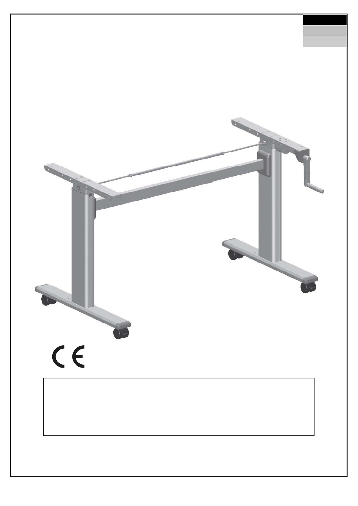
STEELFORCE PRO 100 HC
STEELFORCE
PRO 100 HC
MVL-H11fA1P-0EN-DE-NL
Assembly Manual
Read this manual thoroughly and store in a safe place.
English
Deutsch
Nederlands

STEELFORCE PRO 100 HC
2
Content
1GENERAL ..................................................................................................3
1.1 Local value of the assembly/operating manual .................................3
1.2 Intended use .....................................................................................3
1.3 Improper use.....................................................................................3
1.4 Content box ......................................................................................4
2SAFETY INFORMATION.............................................................................5
2.1 Symbols/warnings.............................................................................5
2.2 Symbols used on the workstation frame............................................5
2.3 Organizational measures ...................................................................5
2.4 Informal safety measures..................................................................5
2.5 Note for those assembling the workstation .......................................5
2.6 Transport and assembly.....................................................................5
2.7 Use of the workstation frame ............................................................6
2.8 Specific dangers ................................................................................6
2.9 Emergency instructions .....................................................................6
2.10 Maintenance and upkeep ...................................................................6
2.11 Cleaning.............................................................................................6
2.12 Persistent risks..................................................................................6
3ASSEMBLY ................................................................................................7
3.1 Checking the items supplied ..............................................................7
3.2 Packaging ..........................................................................................7
3.3 Tightening torques for screws used...................................................7
3.4 Assembly of the workstation .............................................................7
3.4.1 Pre-assembly of the Crossbar......................................................... 7-9
3.4.2 Mounting the Feet........................................................................9-10
3.4.3 Installation of the Wheels / Adjustable Feet........................................11
3.4.4 Mounting the Drive Shaft ................................................................12
3.4.5 Assembly of the Hand Crank ............................................................13
3.4.6 Installation of the Hand Crank .........................................................14
3.4.7 Frame test without Table Top...........................................................14
3.4.8 Assembly of the Table Top ..............................................................14
3.4.9 Assembly of the parts of the Table Top .............................................14
4TECHNICAL SPECIFICATIONS.................................................................15
5OPERATION AND INDICATORS ...............................................................16
6 CUSTOMER SERVICE ...............................................................................16
7 MANUFACTURER.....................................................................................16
8 RECYCLING.............................................................................................16
8.1 Taking the workstation apart...........................................................16
8.2 Recycling .........................................................................................16

STEELFORCE PRO 100 HC
3
1 General
1.1 Local value of the assembly/operating manual
The guiding principle for safe use and trouble-free operation of this workstation frame is
knowledge of basic safety information and regulations. This assembly/operating manual
contains the most important information needed for assembling and operating the work-
station frame safely. This assembly/operating manual, in particular the safety information
contained herein, must be observed by any person building the frame and working on the
finished surface. More importantly, the rules and regulations applying to accident preven-
tion in the locality in which the workstation frame is to be used must be observed at all
times.
1.2 Intended use
The workstation frame must be used only as a height-adjustable workstation for sitting/
standing use in offices or other enclosed areas. The frame must be used for this purpose
only. The workstation frame may be set up and operated solely in office environments. Do
not use the workstation frame in the home. Please observe the provisions of Section 2,
Safety Information. Children may be unaware of the dangers presented by the workstation
frame if unsupervised. Any other use than the above shall be deemed improper. The man-
ufacturer can in no way be held liable for damage arising from improper use.
Intended use shall also include:
Observation of all information from the assembly/operating manual and
Prohibition of any sort of addition to/conversion of the workstation.
1.3 Improper use
Never use the workstation frame to lift people or loads.
Load the table frame only up to the maximum load (see chapter 4 "Technical data").
Do not use the workstation frame in the home; alternatively, use it only in offices.
WARNING: Any changes or modifications not expressly approved by the manufac-
turer could void the user’s authority to operate the equipment.
STEELFORCE PRO 100 HC
4
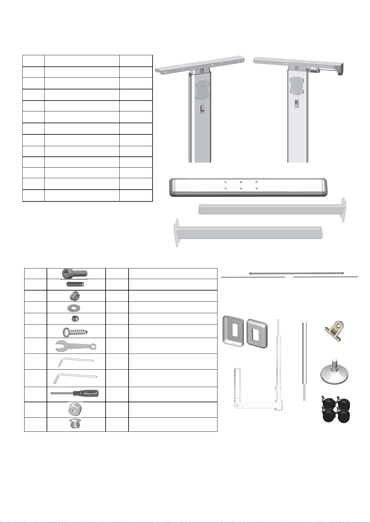
01 02
13.1 8 x M6x25 Bolt
13.2 8 x M6x16 Adjusting Screw
13.3 8 x M6 Collar Nut
13.4 8 x M6 Ring
13.5 2 x M6x6 Set Screw
13.6 10 x Screw 4.5x20mm
13.7 2 x M10 Spanner
13.8 1 x M3 Allen Key
13.9 1 x M5 Allen Key
13.10 1 x Screwdriver
13.11 2x Hexagon-stopper
13.12 4x Cover Cap
# Description Qty
01 Leg L 1
02 Leg R 1
03 Foot 2
04 Inner Crossbar 1
05 Outer Crossbar 1
06 Drive Shaft Kit 1
07 Cover cap, crossbar 2
08 Hand Crank 1
09 Hand Crank Extension 1
10 Hand Crank Guide 1
11 Adjustable foot 4
12 Wheelset 4
06
1.4 Content Box
08
07 09
12
10
Mounting Material and Tools
11
05
03
04
STEELFORCE PRO 100 HC
5
2 Safety Information
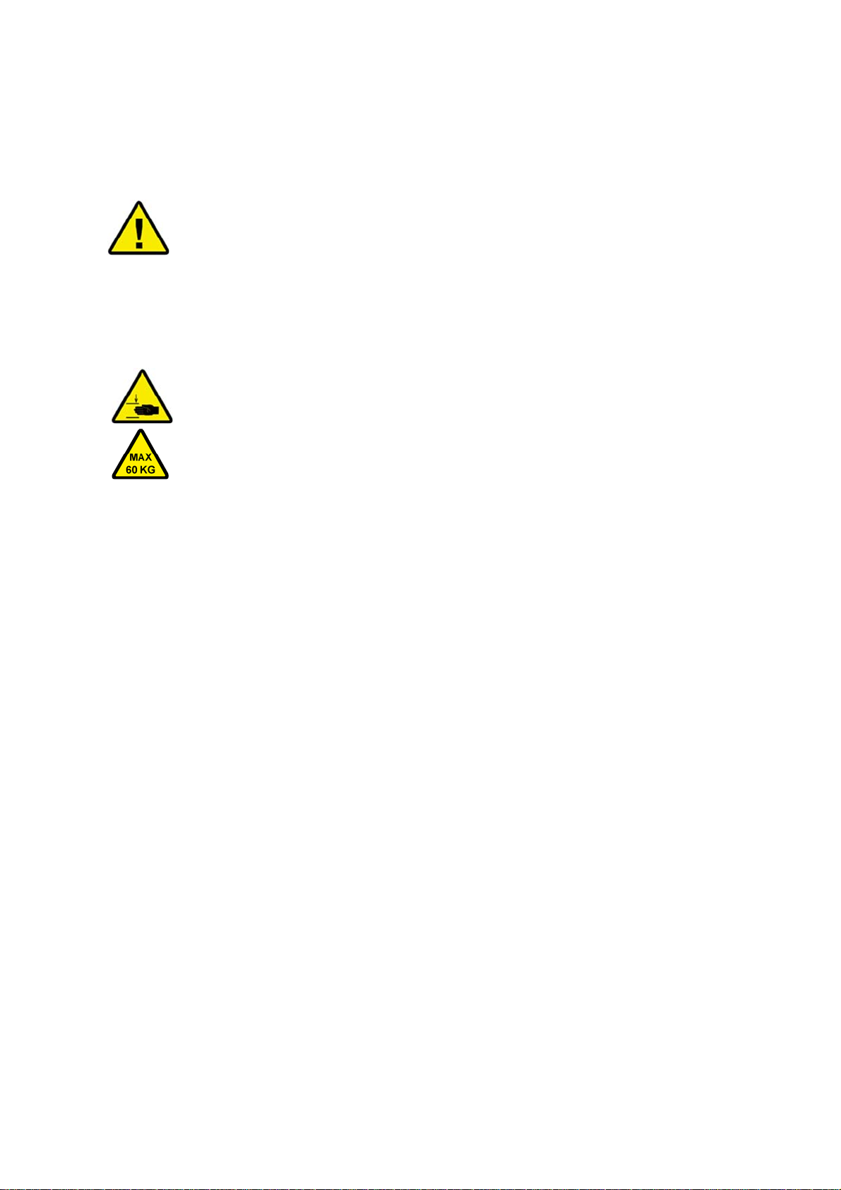
2.1 Symbols/warnings
The assembly/operating manual uses the following terms and signs to indicate dangers:
2.2 Symbols used on the workstation frame
2.3 Organizational measures
The workstation frame can best be assembled by two people. Turning the frame,
once the work surface has been fitted, is a task in particular which requires two
people!
2.4 Informal safety measures
Keep the assembly/operating manual in the place where the workstation frame is
used at all times.
Make sure that all safety information on the table (see Section 2.2, Symbols used
on the workstation frame) is legible, replacing the same if necessary.
2.5 Note for those assembling the workstation
The workstation must be assembled/worked on by persons over the age of 16.
The persons referred to above must have read and understood the assembly/
operating manual.
2.6 Transport and assembly
The workstation frame must be moved by two persons only, and in such cases must
be retracted.
Do not drag or pull the workstation frame over the floor.
Assemble the workstation frame with the supplied tools only. They are the only tools
which ensure that the screws can be tightened to the correct torque.
2.7 Use of the workstation frame
Children may only use the desk under supervision. They may not be aware of the
dangers of the agency. This puts them at serious risk of self-injury, possibly with
fatal consequences.
The desk may only be used in an environment that is suitable for it.
Do not use the desk on an uneven surface. The desk will then not be stable.
This symbol indicates an immediate threatening situation for any person’s
life or health. Failure to adhere to such information may have serious con-
sequences for health, or could even result in life-threatening injury or
death.
This symbol indicates important information. Failure to adhere to such in-
formation could lead to damage to the workstation.
Do not place objects or parts of the body under the workstation frame or
between the cross members. This could cause serious injury.
Do not exceed the maximum permitted load on the workstation frame.
Overloading could lead to breakage and serious injury as a consequence.

STEELFORCE PRO 100 HC
6
2.9 Emergency Instructions
Immediately leave the area around the desk when it starts to move
spontaneously. Do not use the desk. Have the desk repaired by a specialized
company. Do not use the desk again until it has been repaired.
If you notice anything unusual, take the desk out of service immediately. Have
the desk repaired by a specialized company. Do not use the desk again until it
has been repaired.
2.10 Maintenance and upkeep
Always keep the product in good condition. If necessary, have it checked regularly
by a professional.
Do not repair the desk or any of its parts yourself.
Do not make any changes to the worktop or desk construction.
Defective parts may only be replaced with new original parts from the
manufacturer. Only use original replacement parts from the manufacturer. In
doing so, these installation instructions must be observed.
2.11 Cleaning
Once a week, remove the dust from the desk with a dry cloth.
Clean the desk every two weeks with a damp cloth and a mild detergent.
2.12 Persistent risks
This office is built according to the latest state of the art and according to recognized
safety regulations. Nevertheless, its use can
endanger the health and safety of users or third parties and cause damage to the desk
or other parts. The desk may only be used:
for the intended purpose;
if it is completely safe.
2.8 Specific dangers
Adjusting the height of the desk carries the risk of injury. Make sure that no one
else is in the immediate vicinity of the desk.
When mounting the desk, provide enough space to avoid collisions in all possible
directions (e.g. sloping roof, fixed objects, filing cabinets, waste bins, etc.).
Provide sufficient space to avoid collisions if objects such as computers or
peripherals are on the worktop.
Provide a clearance of at least 25mm from all other furniture around the desk
STEELFORCE PRO 100 HC
7
3 Assembly
3.1 Checking the items supplied
Carefully open the cardboard packaging.
In doing so, do not use any long knife blades. They may damage the components
inside.
Check the parts supplied against the list in Section 1.4 Items supplied.
Check the contents for visible transit damage, paying particular attention
to the electrical wiring. In the event of any damage or incorrect components, con-
tact customer service (see Section 6).
Do not attempt to assemble the workstation frame if there is any damage or if
there are any incorrect components.
3.2 Packaging
Remove the packaging. Treat as household waste/paper.
Observe national legislation.
3.3 Tightening torques for screws used
Assemble the workstation frame with the tools supplied only.
3.4 Assembly of the workstation
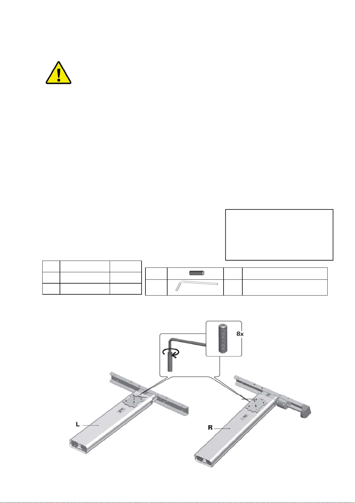
3.4.1 Pre-assembly of the Crossbar
Assemble the following components:
Before attempting assembly, read the safety information in Section
Dimensions Width
Frame Worktop
0,80 m 0,90 cm
1,00 m 1,10 cm
1,20 m 1,30 cm
Place the set screws in the threaded bores.
G Screw the set screws into the threads and tighten them slightly
# Name Qty
01 Leg L 1
02 Leg R 1
13.2 8 x M6x16 Adjusting Screw
13.8 1 x M3 Allen Key
STEELFORCE PRO 100 HC
8
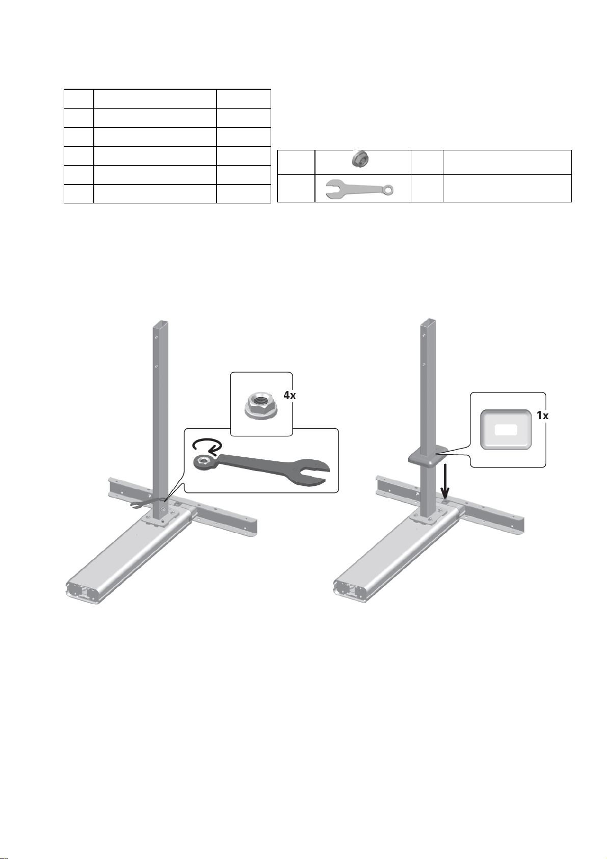
3.4.1 Mounting the Crossbar– Continued
Install the following parts:
13.3 8 x M6 Collar Nut
13.7 2 x M10 Installation Key
# Name Qty
01 Leg L 1
02 Leg R 1
04 Inner Crossbar 1
05 Outer Crossbar 1
07 Cover Cap, crossbar 2
Mount both caps on the ends of the crossbars by pressing them lightly.
Place one leg on the floor in front of you and place the other parallel next to it.
Screw the collar nuts onto the set screws on both legs.
Tighten the collar nuts with the M10 mounting wrench.
STEELFORCE PRO 100 HC
9
13.12 4x Cover cap
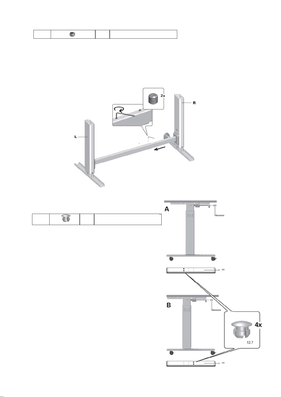
3.4.1 Mounting the Crossbar - continued
Install the following parts:
13.5 2 x M6x6 Adjusting screw
Now turn the legs with the crossbar (with two people). The crossbar is now just
above the floor.
Make sure that the legs do not fall over during assembly.
Extend the frame to the desired width.
Screw the studs into the crossbar and tighten them lightly.
A = position of the T-foot
Attach the blanking cap to the location shown
O R
B = position of the C-foot
Attach the blanking cap to the location shown
3.4.2 Mounting the feet
First choose the position of the legs!
STEELFORCE PRO 100 HC
10
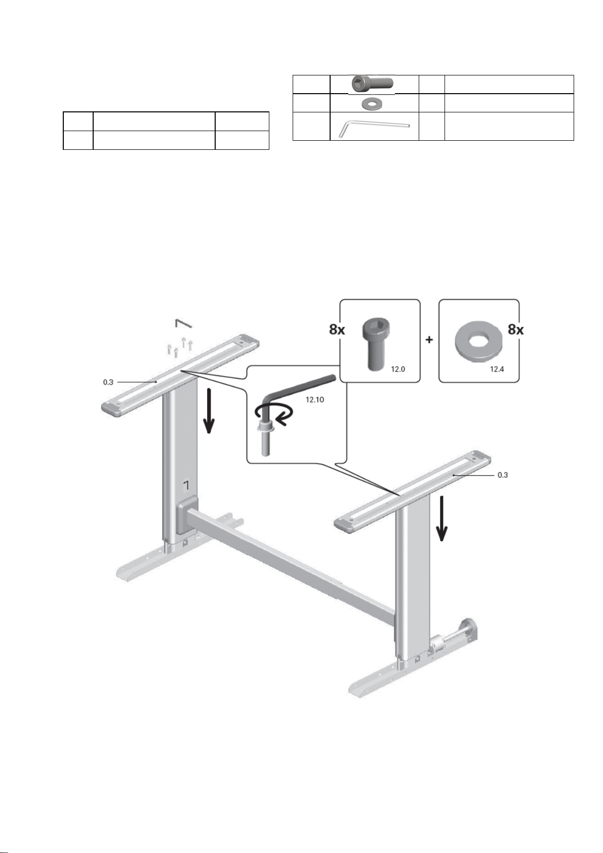
3.4.2 Mounting the Feet —continued
Install the following parts:
# Name Qty
03 Foot 2
13.1 8 x M6x25 Bolt
13.4 8 x M6 Ring
13.9 1 x M5 Allen Key
Mount a foot on each leg. Use four screws and washers for this.
Attach cover caps to the unused holes (as shown on the previous page).
Tighten the eight screws with the Allen key.
STEELFORCE PRO 100 HC
11
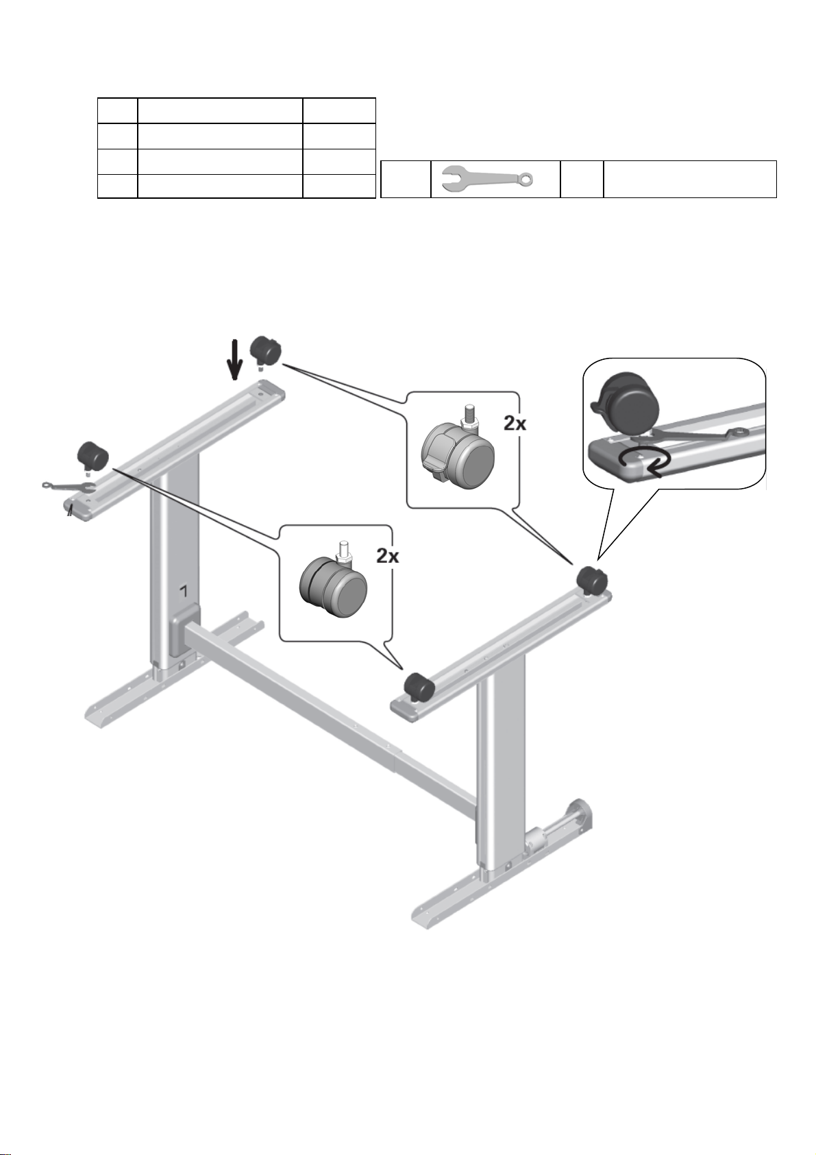
3.4.3 Installation of the Wheels / Adjustable Feet
Install the following parts:
# Name Qty
11 Adjustable foot 4
OR
12 Wheelset 4
Screw either two leveling feet or two wheels into each foot. Use the installation key
for this.
The desk is only stable when the adjustable feet are used. The use of the wheels is
at your own risk!
13.7 2 x M10 Installation Key
STEELFORCE PRO 100 HC
12
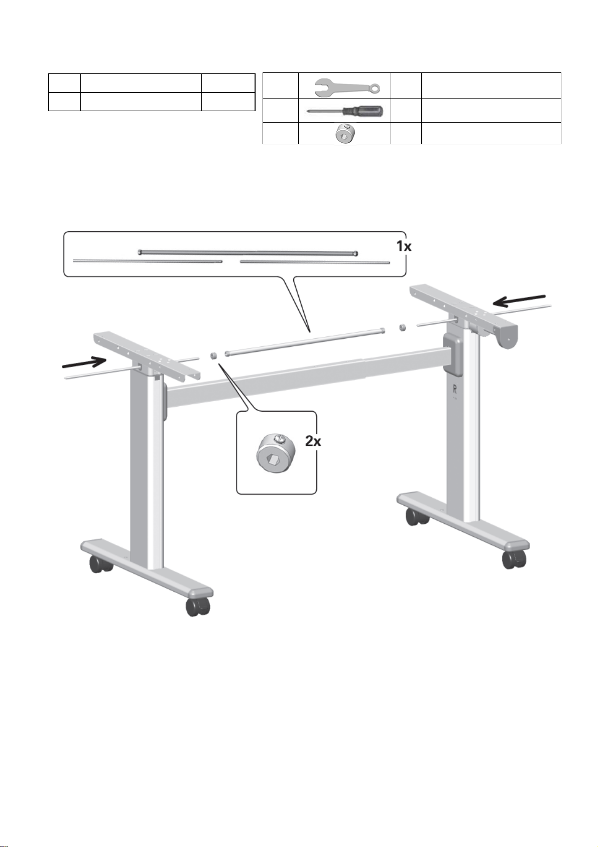
Make sure the legs are in the lowest position (zero position).
Slide the drive shafts (hexagon) from the outside to the inside through the hexagonal
openings in the legs.
Slide the two axles into the frame about 15 cm.
Attach a hex stopper to each axle.
Now slide the two hexagonal shafts into the receiving shaft.
# Name Qty
06 Drive shaft kit 1
3.4.4 Mounting the Drive Shaft
Install the following parts:
13.7 2 x M10 Installation key
13.10 1 x Screwdriver
13.11 2x Hexagon stopper
STEELFORCE PRO 100 HC
13
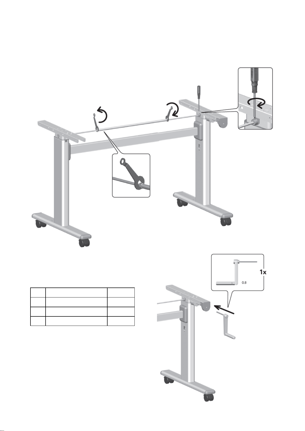
3.4.4 Mounting the Drive Shaft — Continued
Extend the frame to the desired width before beginning the following steps.
Slide both hex shafts into the frame until they touch the outside of the legs.
Now tighten both shafts at the ends with a Phillips screwdriver/slotted screwdriver.
3.4.5 Assembly of the Hand Crank
Install the following components:
When your worktop is in the correct position on the
tray supports, insert the crank into the hexagonal
opening as shown.
# Name Qty
08 Hand crank 1
09 Hand crank extension 1
10 Hand crank guide 1

STEELFORCE PRO 100 HC
14
3.4.6 Installation of the Hand Crank
Install the following components:
If the worktop protrudes far beyond the top supports that the crank has to be extended in
order to adjust the height of the workplace, proceed as follows:
Insert the crank guide into the crank extension.
Insert the crank extension into the hexagonal hole of the blade carrier as shown.
Attach the crank guide to the blade carrier using both # 8x5 / 8 screws.
13.6 2 x Screw 4.5x20mm
# Name Qty
08 Hand crank 1
09 Hand crank extension 1
10 Hand crank guide 1
3.4.7 Frame test without table top
Check the height adjustment function by first moving the frame to the highest position
and then back to the lowest position using the crank.
3.4.8 Assembly of the table top
If you have purchased the frame including worktop, read the loose ones assembly instruc-
tions. The supplied screws (13.6) can only be used in combination with a chipboard with a
thickness of more than 22 mm. Otherwise, follow the instructions in the separate assembly
instructions for the worktop.
3.4.9 Assembly of the parts of the table top
If you have purchased the frame including worktop, read the loose ones assembly instruc-
tions.
STEELFORCE PRO 100 HC
15
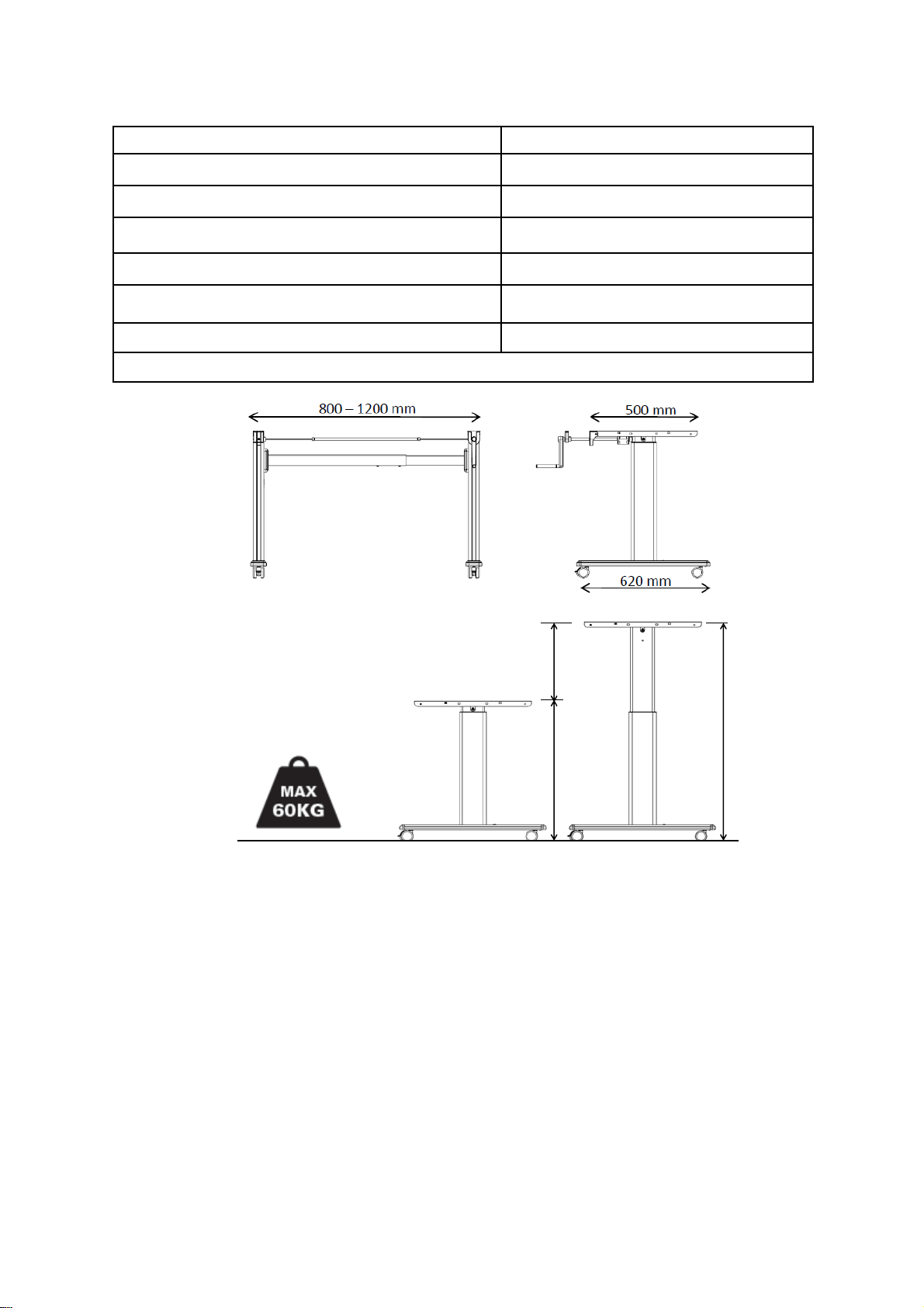
4 Technical Specifications
Frame for a manually height-adjustable sitting / standing workstation
Operating and installation manual version MVL-H11fA1P-0EN-DE-NL
System Single stage, hand crank
Material Steel and plastic
Stroke (max.) 410 ± 10 mm
Frame load (max.) Surface load 60 kg
Frame weight 16 kg
Stroke per revolution of the hand crank 13 mm per pendulum swing
Only for indoor use !!!
Minimum frame height 640 mm 680 mm
Maximum frame height 1050 mm 1090 mm
Maximum stroke 410 mm
Frame width 800 - 1200
Frame depth 620
Minimum worktop depth 500
Maximum frame load / surface load 60
Stroke per revolution 13 mm per pendulum swing
410 mm
mm
mm
mm
kg
680 mm 410 mm
1090 mm
(* Average tolerances= ± 10 mm)

STEELFORCE PRO 100 HC
16
5 Operation and Indicators
6 Customer Service
When contacting the customer service please
8 Recycling
8.1 Taking the workstation apart
In case of de-assembling please follow the manual backwards or contact cus-
tomer service.
8.2 Recycling
Please split all parts to their type of material. Keep notice of National restrictions!
7 Manufacturer
Retailer:
Actiforce International B.V.
Het Steenland 20
3751 LA Bunschoten-Spakenburg
The Netherlands
+31 (0)33 4600120
www.actiforce.com
Please observe the provisions of chapter 2 “Safety Infor-
mation” on page 5, especially:
Children may only use the desk under supervision. They may
not be aware of the dangers of the agency. Because of this,
they are in serious danger of that they may injure themselves,
possibly with fatal consequences. Protect the frame from the
use by children. Provide sufficient space to avoid collisions,
even when objects such as computers, work materials and the
like are on the worktop.
Table of contents
Other STEELFORCE Indoor Furnishing manuals


Popular Indoor Furnishing manuals by other brands


Courtyard Creations
Courtyard Creations RTS009P Assembly instructions

Rauch
Rauch M1793 Assembly instructions

Dentsply Sirona
Dentsply Sirona Hugo operating instructions

Accentrics Home
Accentrics Home DS-D477-701-1 Assembly instructions

Hülsta
Hülsta now! flexx PASSEPARTOUT Assembly instruction

Wazo
Wazo MAURA MANGO B1039Q Assembly instructions