STEELFORCE Pro 870 SLS EN527 User manual

English
Deutsch
Nederlands
SLS-IM0084-0EN-DE-NL
Steelforce Pro 870 SLS EN527
Assembly anual
Read this manual thoroughly and store in a safe place
ontageanleitung
Bitte sorgfältig lesen und sicher aufbewahren
ontagehandleiding
Lees deze handleiding aandachtig door en bewaar deze goed
ACTIFORCE MECHATRONICS TECHNOLOGY SDN. BHD.
ONCE PRINTED CONSIDER REFERENCE ONLY
(Not subject for revision change)

2
English
Content
1 GENERAL ......................................................................................................................................................................... 5
1 1 Local value of the assembly/operating manual 5
1 2 Intended use 5
1 3 Improper use 5
1 4 Grounding Instruction 5
1 5 Danger 5
1 6 Content box 6-7
2 SAFETY INFOR ATION .................................................................................................................................................... 8
2 1 Symbols/warnings 8
2 2 Symbols used on the workstation frame 8
2 3 Maximum weight allowed on frame 8
2 4 Maximum weight allowed per column ................................................................................................................... 9
2 5 Organizational measures 9
2 6 Informal safety measures 9
2 7 Note for those assembling the workstation 9
2 8 Transport and assembly 9
2 9 Use of the workstation frame 9
2 10 Specific dangers 9
2 11 In an emergency 10
2 12 Maintenance and upkeep 10
2 13 Cleaning 10
2 14 Persistent risks 10
3 ASSE BLY .................................................................................................................................................................... 11
3 1 Pre-assembly of the Crossbars 11
3 1 1 Recommended Top Sizes 11
3 1 2 120 cm Frame Set-Up Guide 12
3 2 Mounting the Feet 13
3 3 Mounting the Crossbar 13
3 4 Mounting the Top Support 14
3 5 Adjustment of the Frame Width 14
3 6 Mounting the Spacers 15
3 7 Mounting the Cable Clips 15-16
3 8 Connecting the Electrical Components 17
3 9 Mounting the table top 18
3 10 Mounting the power supply underneath the table top 18
3 11 Mounting the Wire Clip 19-21
3 12 Clearance around the wall or moving parts 25mm of the table top 21
3 13 Frame Test without table top 22-23
4 CORRECT POSITION OF SEAT ........................................................................................................................................ 24
5 TECHNICAL SPECIFICATIONS .................................................................................................................................. 25-26
6 OPERATION AND INDICATORS .................................................................................................................................... 27
6 1 Indicators 27
7 TROUBLESHOOTING ...................................................................................................................................................... 27
8 CUSTO ER SERVICE ..................................................................................................................................................... 28
9 ANUFACTURER ........................................................................................................................................................... 28
10 RECYCLING ................................................................................................................................................................... 28
10 1 Taking the workstation out of active duty 28
10 2 Taking the workstation apart 28
10 3 Recycling 28
ACTIFORCE MECHATRONICS TECHNOLOGY SDN. BHD.
ONCE PRINTED CONSIDER REFERENCE ONLY
(Not subject for revision change)

3
Deutsch
Inhaltsverzeichnis
1 ALLGE EINES ................................................................................................................................................................. 29
1 1 Stellenwert der Montage-/Bedienungsanleitung 29
1 2 Verwendungszweck 29
1 3 Unsachgemäße Verwendung 29
1 4 Erdungsvorschrift 29
1 5 Gefahr 29
1 6 Lieferumfang 30-31
2 SICHERHEITSHINWEISE ................................................................................................................................................... 32
2 1 Symbol– und Hinweiserklärungen 32
2 2 Verwendete Symbole am Tischgestell 32
2 3 Zulässiges Gesamtgewicht auf dem Tischgestell 32
2 4 Zulässiges Gesamtgewicht pro Säule 33
2 5 Organisatorische Maßnahmen 33
2 6 Empfohlene Sicherheitsmaßnahmen 33
2 7 Hinweise zur Montage 33
2 8 und Montage 33
2 9 Benutzung des Tischgestells 33
2 10 Besondere Gefahrenstellen 33
2 11 Hinweise für den Notfall 34
2 12 Wartung und Instandhaltung 34
2 13 Reinigung 34
2 14 Restrisiken 34
3 ONTAGE ...................................................................................................................................................................... 35
3 1 Vormontage der Traverse 35
3 1 1 Empfohlene Tischplattenmaße 35
3 1 2 Einstellung der Traversen auf 120 cm 36
3 2 Montage der Kufen 37
3 3 Montage der Traversen 37
3 4 Montage der Plattenträger 38
3 5 Einstellen der Gestellbreite 38
3 6 Montage der Abstandhalter 39
3 7 Montage der Kabelhalterungen 39-40
3 8 Anschließen der elektrischen Bauteile 41
3 9 Montage der Tischplatte 42
3 10 Montage des Netzteils unter der Tischplatte 42
3 11 Montage der Kabelclips 43-45
3 12 Sicherheitsabstand zur Wand oder beweglichen Teilen von 25 mm um die Tischplatte 45
3 13 Test und Inbetriebnahme ohne Tischplatte 46-47
4 ERGONO ISCHE SITZEINSTELLUNG .............................................................................................................................. 48
5 TECHNISCHE DATEN ................................................................................................................................................. 49-50
6 BETRIEBSHINWEISE .......................................................................................................................................................... 51
6 1 Fehlfunktionen 51
7 FEHLERBEHEBUNG .......................................................................................................................................................... 51
8 KUNDENDIENST .............................................................................................................................................................. 52
9 HERSTELLER ..................................................................................................................................................................... 52
10 ENTSORGUNG ................................................................................................................................................................ 52
10 1 Außerbetriebnahme des Tischgestells 52
10 2 Tischgestell abbauen und ggf zerlegen 52
10 3 Entsorgung 52
ACTIFORCE MECHATRONICS TECHNOLOGY SDN. BHD.
ONCE PRINTED CONSIDER REFERENCE ONLY
(Not subject for revision change)

4
Nederlands
Inhoudsopgave
1 ALGE EEN ................................................................................................................................................................... 53
1 1 Waarde van de montage- en gebruikershandleiding 53
1 2 Beoogd gebruik 53
1 3 Onjuist gebruik 53
1 4 Aarding instructie 53
1 5 Gevaar 53
1 6 Inhoud verpakking 54-55
2 VEILIGHEIDSINSTRUCTIES ............................................................................................................................................... 56
2 1 Verklaring van symbolen en instructies 56
2 2 Gebruikte symbolen op het frame 56
2 3 Maximaal toegestaan gewicht op het frame 56
2 4 Maximaal toegestaan gewicht per kolom .......................................................................................................... 57
2 5 Organisatorische maatregelen 57
2 6 Informele veiligheidsmaatregelen 57
2 7 Vereisten aan de monteurs 57
2 8 Transport en montage 57
2 9 Gebruik van het frame 57
2 10 Specifieke gevaren 57
2 11 Instructies voor noodgevallen 58
2 12 Onderhoud en instandhouding 58
2 13 Reiniging 58
2 14 Overige risico’s 58
3 ONTAGE ..................................................................................................................................................................... 59
3 1 Voormontage van de crossbar 59
3 1 1 Aanbevolen bladmaat 59
3 1 2 120cm Frame instelling 60
3 2 Montage van de voeten 61
3 3 Montage van de crossbar 61
3 4 Montage van de bladdragers 62
3 5 Instellen van de frame-breedte 62
3 6 Montage van de afstandhouders 63
3 7 Montage van de kabelbinders 63-64
3 8 Aansluiten van de elektrische componenten 65
3 9 Montage van het werkblad 66
3 10 Montage van de handbediening 66
3 11 Montage van de kabelclips 67-69
3 12 Afstand van 25 mm tussen de muur of andere objecten en het werkblad .................................................... 69
3 13 Frame test zonder werklad 70-71
4 CORRECTE ZITPOSITIE ..................................................................................................................................................... 72
5 TECHNISCHE SPECIFICATIES .................................................................................................................................... 73-74
6 BEDIENING EN GEBRUIKSAANWIJZINGEN ................................................................................................................... 75
6 1 Gebruiksaanwijzingen 75
7 PROBLEE OPLOSSINGEN ............................................................................................................................................. 75
8 KLANTENSERVICE .......................................................................................................................................................... 76
9 FABRIKANT ..................................................................................................................................................................... 76
10 RECYCLING ................................................................................................................................................................... 76
10 1 Buitenbedrijfstelling van het frame 76
10 2 Demontage van het frame 76
10 3 Recycling 76
ACTIFORCE MECHATRONICS TECHNOLOGY SDN. BHD.
ONCE PRINTED CONSIDER REFERENCE ONLY
(Not subject for revision change)

5
English
1 General
1.1 Local value of the assembly/Operating anual
The guiding principle for safe use and trouble-free operation of this workstation frame is knowledge of
basic safety information and regulations This assembly/operating manual contains the most important
information needed for assembling and operating the workstation frame safely This assembly/
operating manual, in particular the safety information contained herein, must be observed by any
person building the frame and working on the finished surface More importantly, the rules and regula-
tions applying to accident prevention in the locality in which the workstation frame is to be used must
be observed at all times
1.2 Intended use
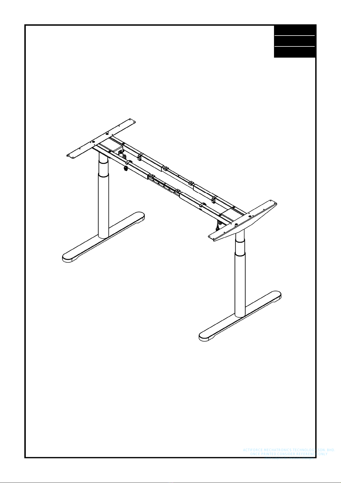
The workstation frame must be used only as a height-adjustable workstation for sitting/standing use in
offices or other enclosed areas The frame must be used for this purpose only Any other use than the
above shall be deemed improper The manufacturer can in no way be held liable for damage arising
from improper use This appliance can be used by children aged from 8 years and above and persons
with reduced physical, sensory or mental capabilities or lack of experience and knowledge if they
have been given supervision or instruction concerning use of the appliance in a safe way and under-
stand the hazards involved Children should be supervised to ensure that they do not play with the
appliance, cleaning and user maintenance shall not be made by children without supervision
Intended use shall also include:
• Observation of all information from the assembly/operating manual and
• Prohibition of any sort of addition to/conversion of the workstation
1.3 Improper use
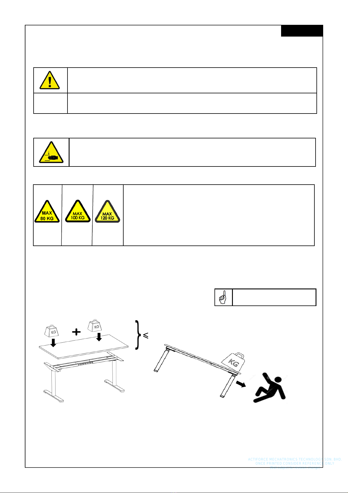
• Never use the workstation frame to lift people or loads
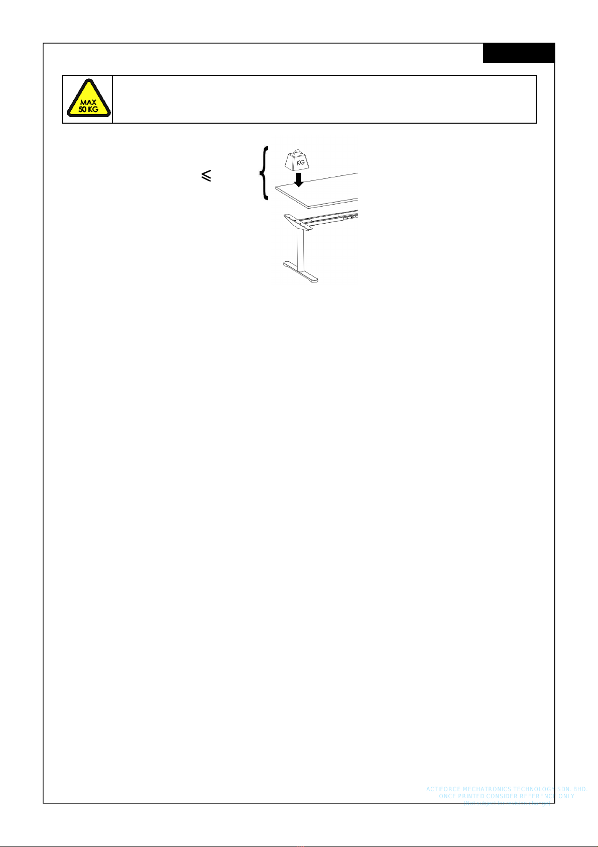
• Do not exceed the maximum load of the workstation frame
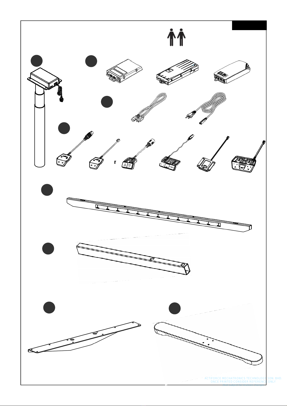
• Operate workstation only with power supply unit which is included in delivery.
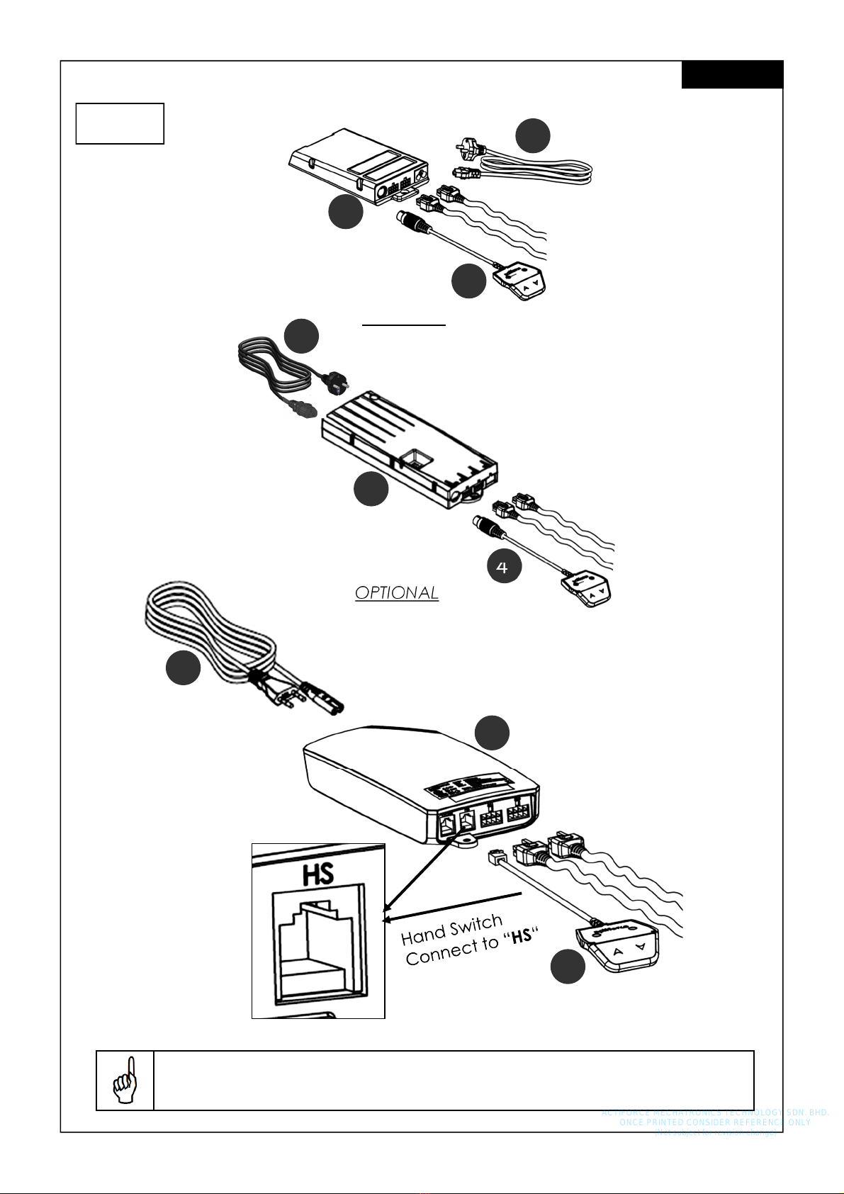
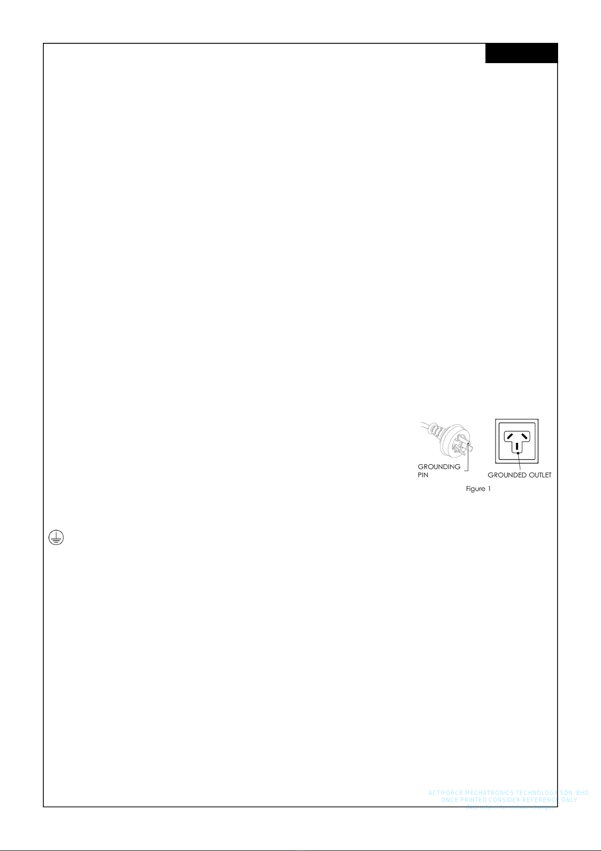
1.4 Grounding Instruction (System with S ART/CO PACT Controller)
This workstation frame must be grounded Connect this workstation frame
to a properly grounded outlet only If it should malfunction or breakdown,
grounding provides a path of least resistance for electric current to re-
duce the risk of electric shock This workstation frame is equipped with a
cord having a grounding plug like the plug illustrated in Figure 1 The plug
must be plugged into an appropriate outlet that is properly installed and
grounded in accordance with all local codes and ordinances
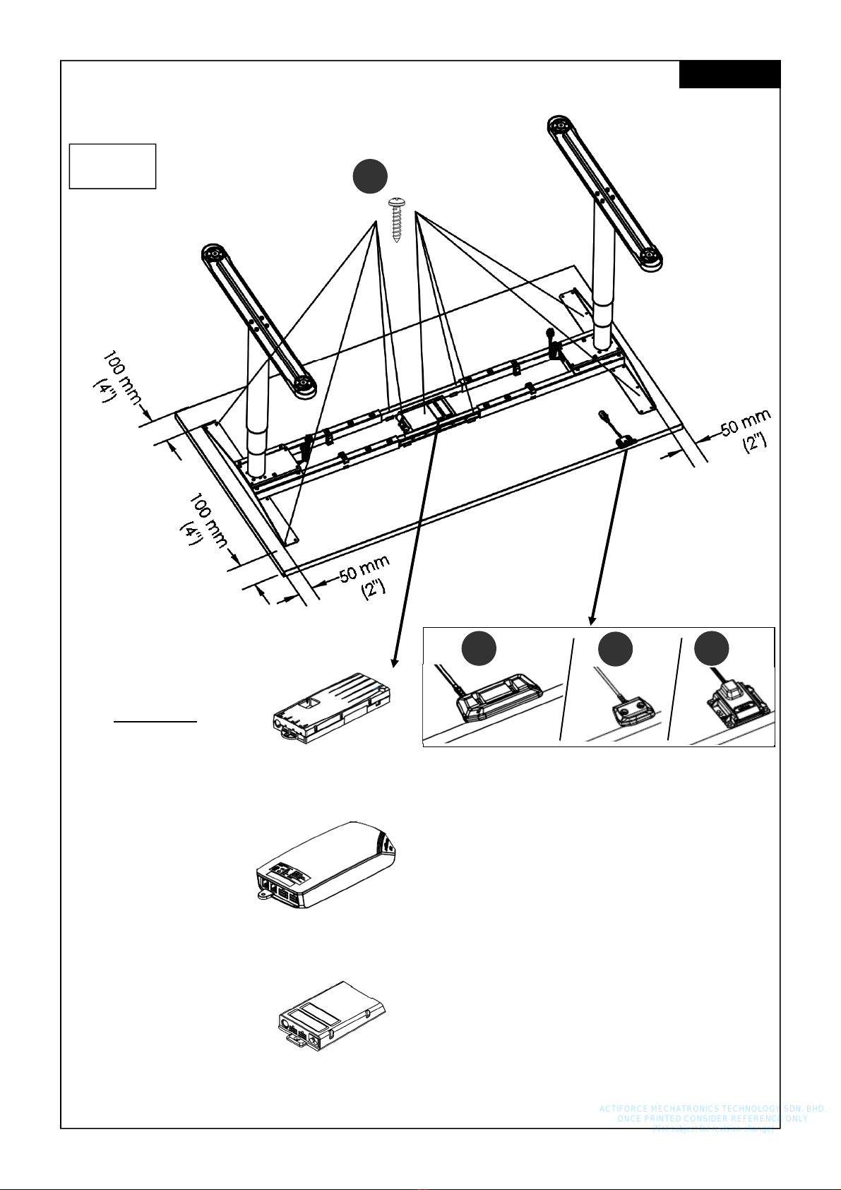
This appliance incorporates an earth connection for functional purposes only.
For protective earth, the terminal is intended to connect with equipotential bonding of building
where the workstation frame is being setup Terminals for the connection of external equipotential
bonding conductors shall allow the connection of conductors having nominal cross-sectional areas of
2,5 mm2 to 6 mm2.
1.5 Danger
Improper connection of the workstation frame grounding conductor can result in a risk of electric
shock Check with a qualified electrician if you are in doubt as to whether the product is properly
grounded Do not modify the plug provided with the product
If the supply cord is damaged, it must be replaced by a special cord or assembly available from the
manufacturer or its service agent
WARNING: Any changes or modifications not expressly approved by the manufacturer could
void the user’s authority to operate the equipment.
ACTIFORCE MECHATRONICS TECHNOLOGY SDN. BHD.
ONCE PRINTED CONSIDER REFERENCE ONLY
(Not subject for revision change)

6
English
Assembly requires 2 people!
1.6 Content Box
Items
1x
3
1x
2
**
or or
or
or or
2x
5
4x
6
2x
1
2x
8
2x
7
1x
4
or or or
ACTIFORCE MECHATRONICS TECHNOLOGY SDN. BHD.
ONCE PRINTED CONSIDER REFERENCE ONLY
(Not subject for revision change)

7
** Control Unit 2(a) :
I SMART-e-2-actiforce-EU : Input: 220-240Vac, 50-60Hz, 2 5A; Output: 288VA / 24V
II SMART-e-2-actiforce-US : Input: 120Vac, 60Hz, 5A; Output: 216VA / 24V
** Control Unit 2(b) :
I COMPACT-e-2L-actiforce-EU : Input: 220-240Vac, 50-60Hz, 5A; Output: 288VA / 24V
II COMPACT-e-2L-actiforce-US : Input: 120Vac, 60Hz, 10A; Output: 288VA / 24V
III COMPACT-e-3-actiforce-JAP : Input: 100Vac, 50-60Hz, 620VA; Output: 24V / 15A
5V / 300mA
** Control Unit 2(c) :
ControlForce 2 : Input: 100-120Vac, 60Hz, 5A max; Output: 24Vdc 9 2A
220-240Vac, 50Hz, 2A max; Output: 24Vdc 5A
Table : 24VDC, 4A
English
8x
E
M8x50
8x
F
M6x16
8x
G
M10x35
Hardware Kit
Tools
6x D
4x
A 4x
B 2x
C
4 5x20
28x
H 30x
ACTIFORCE MECHATRONICS TECHNOLOGY SDN. BHD.
ONCE PRINTED CONSIDER REFERENCE ONLY
(Not subject for revision change)

8
2 Safety Information
2.1 Symbols/Warnings
The assembly/operating manual uses the following terms and signs to indicate dangers:
This symbol indicates an immediate threatening situation for any person’s life or health
Failure to adhere to such information may have serious consequences for health, or
could even result in life-threatening injury or death
This symbol indicates important information Failure to adhere to such information
could lead to damage to the workstation
2.2 Symbols used on the workstation frame
Do not place objects or parts of the body under the workstation frame or between
the cross members This could cause serious injury or even result in death
2.3 aximum weight allowed on frame
80/100/120 kg
Example (a) :
> 80/100/120 kg
English
The entire weight should be
evenly distributed
Do not exceed the maximum permitted load of
(a) 80 kg including table top (Smart-e-2)
(b) 100 kg including table top (Compact-e-2)
(c) 120 kg including table top (ControlForce 2)
on the workstation frame Avoid unbalanced load, distribute the
weight evenly, otherwise overload may occur Overloading a
frame may cause breakage and close by individuals may suffer
serious injuries as a consequence
20KG
ACTIFORCE MECHATRONICS TECHNOLOGY SDN. BHD.
ONCE PRINTED CONSIDER REFERENCE ONLY
(Not subject for revision change)

9
2.5 Organizational measures
• The workstation frame can best be assembled by two people Turning the frame, once the
work surface has been fitted, is a task in particular which requires two people!
2.6 Informal safety measures
• Keep the assembly/operating manual in the place where the workstation frame is used at all
times
• Make sure that all safety information on the table (see Section Symbols used on the workstation
frame) is legible, replacing the same if necessary
2.7 Note for those assembling the workstation
• The workstation must be assembled/worked on by persons over the age of 16
• The persons referred to above must have read and understood the assembly /operating man-
ual
2.8 Transport and assembly
• The workstation frame must be moved by two persons only, and in such cases must be retract-
ed
• Do not drag or pull the workstation frame over the floor
• Assemble the workstation frame with the supplied tools only They are the only tools which en-
sure that the screws can be tightened to the correct torque
2.9 Use of the workstation frame
• Do not allow children to use the workstation frame unsupervised Children may be unaware of
the dangers presented by the workstation frame They would be in serious danger of injuring
themselves, possibly even with fatal consequences Further adjustment must then be impossi-
ble as a safeguard against use by children
• The workstation frame must only be used in appropriate areas
• Do not use the workstation frame on an uneven surface In such conditions it will not be steady
• Never exceed the maximum load on the workstation frame
2.10 Specific dangers
• When adjusting the height of the frame there is danger of injury Make sure that there is no-one
else in the immediate surroundings of the frame
• When assembling the workstation frame, make sure there is ample space to avoid collisions
(i e inclination of roof, fixed objects, filing cabinets, waste-paper bins etc ) in all imaginable
directions
• Make sure there is ample space to avoid collisions if there are objects on the work surface such
as computers or computer peripherals
• Make sure there is clearance of at least 25 mm from all other furniture, all around the
workstation frame
English
2.4 aximum weight allowed per column
Do not exceed the maximum permitted load of 50 kg (including table top) on a col-
umn Overloading a frame may cause breakage and close by individuals may suffer
serious injuries as a consequence
50 kg
ACTIFORCE MECHATRONICS TECHNOLOGY SDN. BHD.
ONCE PRINTED CONSIDER REFERENCE ONLY
(Not subject for revision change)

10
2.11 In an emergency
• Stop using the workstation frame at once if you notice anything unusual (strange sounds etc )
• Have the workstation frame repaired by specialists Refrain from using the workstation frame
until it has been successfully repaired
2.12 aintenance and upkeep
• The workstation frame and its components are low-maintenance items and need no special
regular maintenance
• Do not perform any repairs on the work surface or other components yourself
• Do not alter the construction of the work surface or its frame
• Any faulty components removed must be replaced with new, original components from the
manufacturer Use only original replacement parts made by the manufacturer Have any such
work carried out by a specialist, making reference to this Assembly/operating manual
2.13 Cleaning
• Always unplug this workstation from the electrical outlet before cleaning
• Dust the workstation frame once a week with a dry cloth
• Clean the workstation frame with a damp cloth and a weak solution of cleaner once a fort-
night
2.14 Persistent risks
This workstation frame has been built to the state of the art and to recognized safety regulations
Nonetheless, its use may constitute a risk to the health and safety of users or third parties, damage to
the workstation frame or to other items The workstation frame must be used only:
• for the purpose for which it was intended
• if it is completely safe to do so
English
ACTIFORCE MECHATRONICS TECHNOLOGY SDN. BHD.
ONCE PRINTED CONSIDER REFERENCE ONLY
(Not subject for revision change)

11
3 Assembly English
Before attempting assembly, read the Safety Information in Section 2.
To protect components and the floor from scratches, it is advisable to use a pad before
assembly You can, for example, use the supplied cardboard by unfolding it
1
Do not tighten the set screws on the crossbars yet!
3.1 Pre-assembly of the Crossbars
Frame set-up Width / size table top Depth / size table top Table Top Thickness
110 cm 120 cm 80 cm 2 5 cm
130 cm 140 cm 80 cm 2 5 cm
150 cm 160 cm 80 cm 2 5 cm
170 cm 180 cm 80 cm 2 5 cm
3.1.1 Recommended Top Sizes
G
6
6
5
ACTIFORCE MECHATRONICS TECHNOLOGY SDN. BHD.
ONCE PRINTED CONSIDER REFERENCE ONLY
(Not subject for revision change)

12
120 cm Frame set-up - offset the inner crossbar to 110 cm and 130 cm as shown in diagram
below.
3.1.2 120 cm Frame Set-Up Guide English
2 5 6
6
ACTIFORCE MECHATRONICS TECHNOLOGY SDN. BHD.
ONCE PRINTED CONSIDER REFERENCE ONLY
(Not subject for revision change)

13
3
3.2 ounting the Feet English
A
8
F
1 2x
A
6 5 6 E
E
4
3.3 ounting the Crossbar
ACTIFORCE MECHATRONICS TECHNOLOGY SDN. BHD.
ONCE PRINTED CONSIDER REFERENCE ONLY
(Not subject for revision change)

14
English
5
3.4 ounting the Top Support
7
E
7
E
6
3.5 Adjustment of the Frame Width
Adjust the frame into the desired width Tighten the set screws on the crossbar with
Allen key M5 ACTIFORCE MECHATRONICS TECHNOLOGY SDN. BHD.
ONCE PRINTED CONSIDER REFERENCE ONLY
(Not subject for revision change)

15
B
3.6 ounting the Spacers
3.7 ounting the Cable Clips
7
8
English
D
ACTIFORCE MECHATRONICS TECHNOLOGY SDN. BHD.
ONCE PRINTED CONSIDER REFERENCE ONLY
(Not subject for revision change)

16
9
English
D
ACTIFORCE MECHATRONICS TECHNOLOGY SDN. BHD.
ONCE PRINTED CONSIDER REFERENCE ONLY
(Not subject for revision change)

17
Keep in mind that the desk which you are assembling is height adjustable The cables
of the electrical components must be able to freely follow the movement of the desk
3.8 Connecting the Electrical Components English
3
** 2
4
10
OPTIONAL
3
** 2
4
OPTIONAL
2
4
3
ACTIFORCE MECHATRONICS TECHNOLOGY SDN. BHD.
ONCE PRINTED CONSIDER REFERENCE ONLY
(Not subject for revision change)

18
H 26x
2x
H 4x
H
2x
H
3.9 ounting the table top
3.10 ounting the power supply underneath the table top
11
English
or
or
OPTIONAL
ACTIFORCE MECHATRONICS TECHNOLOGY SDN. BHD.
ONCE PRINTED CONSIDER REFERENCE ONLY
(Not subject for revision change)

19
C
D
Mount the wire clips for cable Peel off paper backing
and stick to table top Place wire into each wire clip
3.11 ounting the Wire Clip
12
English
Bond losse cable together with
cable clip
ACTIFORCE MECHATRONICS TECHNOLOGY SDN. BHD.
ONCE PRINTED CONSIDER REFERENCE ONLY
(Not subject for revision change)

20
C
D
13
OPTIONAL
English
Mount the wire clips for cable Peel off paper backing
and stick to table top Place wire into each wire clip
Bond losse cable
together with cable clip
ACTIFORCE MECHATRONICS TECHNOLOGY SDN. BHD.
ONCE PRINTED CONSIDER REFERENCE ONLY
(Not subject for revision change)
Table of contents
Other STEELFORCE Indoor Furnishing manuals