4
SAFE OPERATION
RE-FUELING
•ALWAYS STOP THE ENGINE and allow it to cool
before refueling. NEVER remove the gas cap to
add fuel while the engine is running, and never
ll the gas tank on an engine that has been
running and is sll hot – gas spilled on a hot
engine can ignite.)
•Never smoke while refueling.
•Do not overll fuel tank.
•Follow warning label on fuel tank.
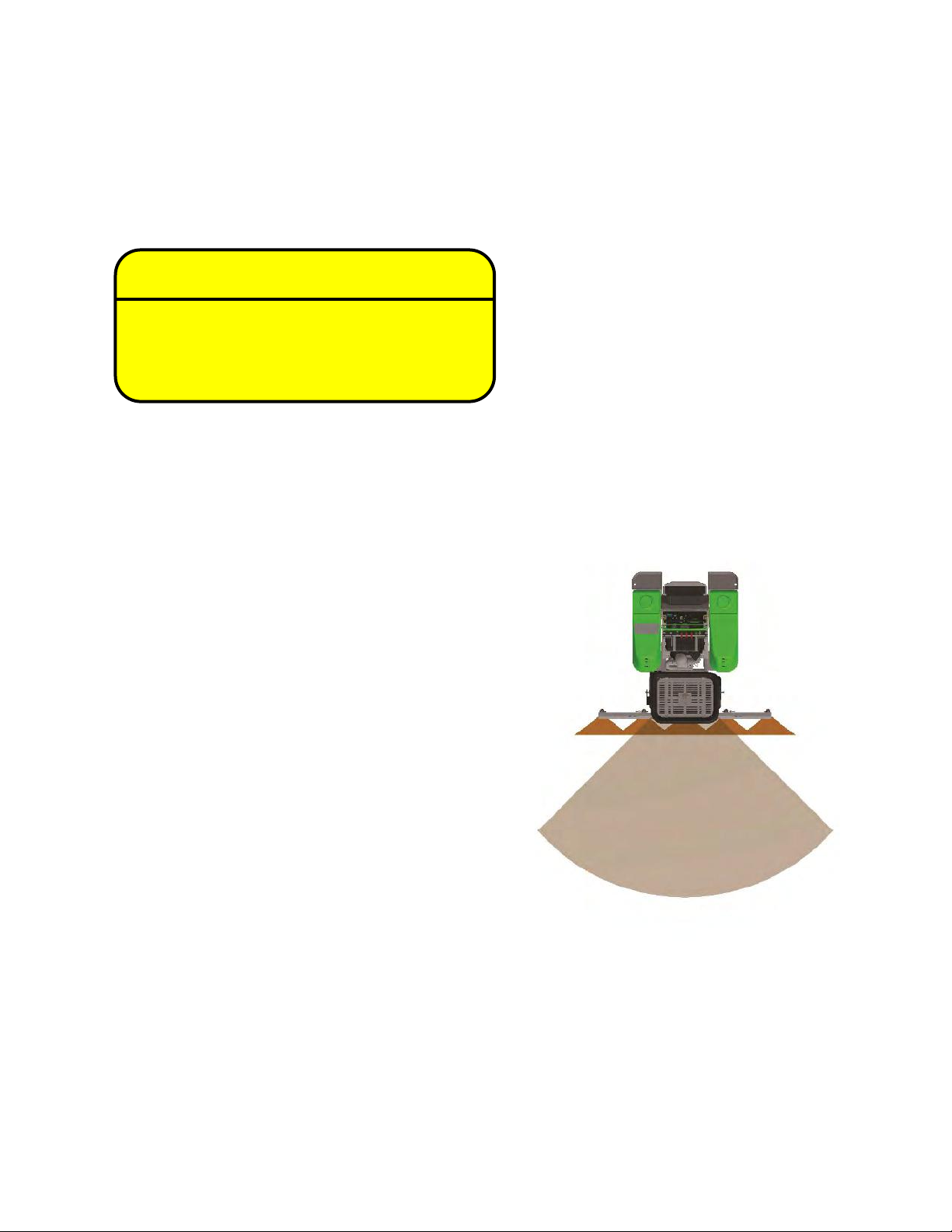
SLOPE OPERATION
•Cease operaon if stability is quesonable, or if
you are unsure of the ability to connue safely.
•Keep alert for hidden hazards on the terrain.
•Stay away from drop-os, ditches and
embankments.
•Never operate on slope angles greater than 13°
with the SG in its basic conguraon. The basic
conguraon is the SG with hopper and no
other aachments. (A 13° slope is a slope that
rises 1.4 m (4.6 ) over a horizontal distance of
6.1 m (20 ).
•When using aachments, never operate the SG
on slope angles greater than 10°. The addion
of an extra tank, or other aachments will
increase the risk of a rollover. (A 10° slope is a
slope that rises 1 m (3.5 ) over a horizontal
distance of 6.1 m (20 ).
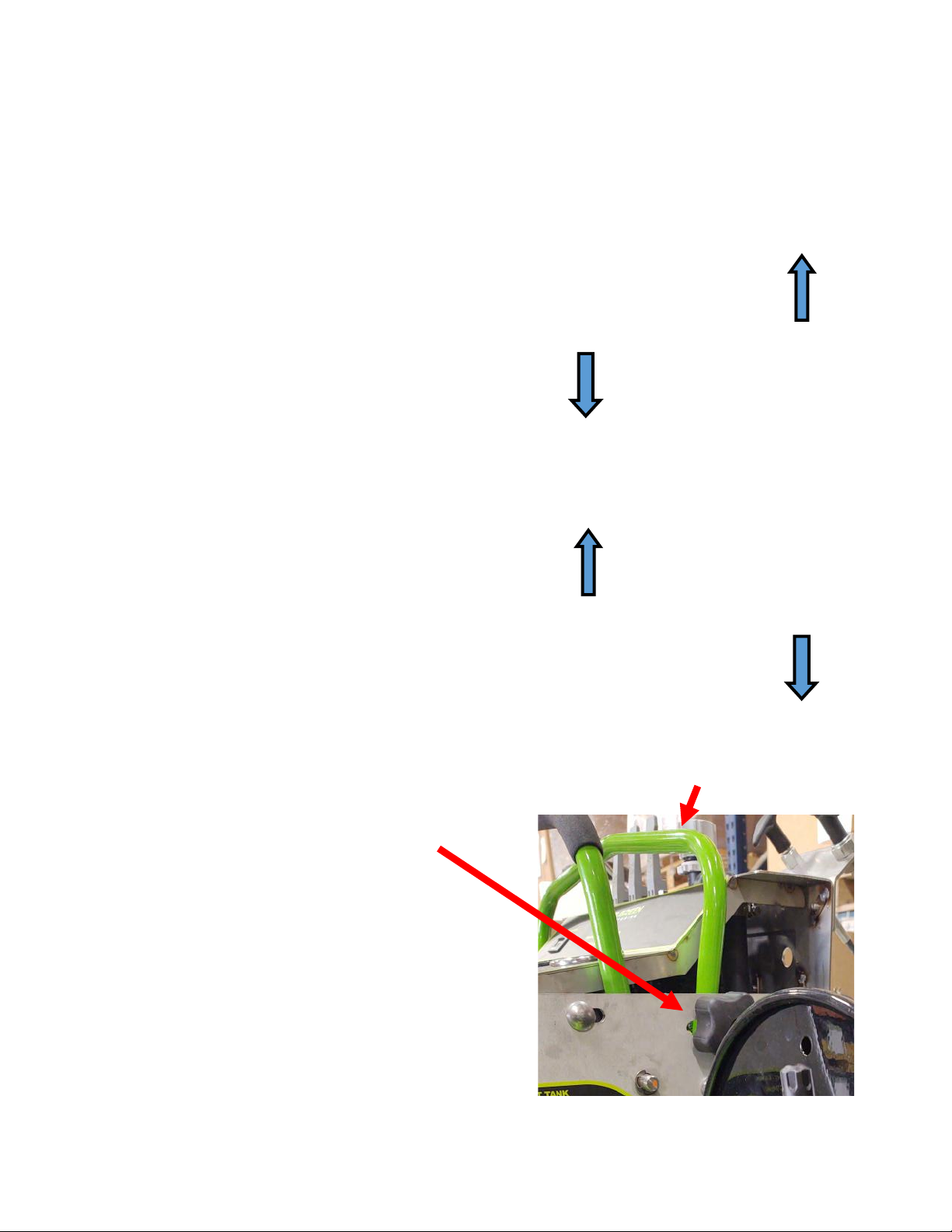
BRAKE
DISENGAGED
BRAKE
ENGAGED
GENERAL OPERATION
•Do not operate the machine while under the
inuence of alcohol or drugs.
•Only allow responsible adults, who have
pracced driving the zero radius SG and are
familiar with the instrucons to operate the
machine. Local restricons may restrict the age
of the operator.
PARKING/BRAKE OPERATION
•To engage the brake, pull down and in on the
lever on the lower poron of the right upright
of the machine.
•Lock the parking brake.
•Stop the engine.
CAUTION!
THE FOLLOWING IMPORTANT SAFETY INSTRUCTIONS WHICH, IF NOT FOLLOWED,
COULD ENDANGER THE PERSONAL SAFETY AND/OR PROPERTY OF YOURSELF AND OTHERS. READ AND
FOLLOW ALL INSTRUCTIONS IN THIS MANUAL BEFORE ATTEMPTING TO OPERATE YOUR UNIT. FAILURE TO
COMPLY WITH THESE INSTRUCTIONS MAY RESULT IN PERSONAL INJURY.