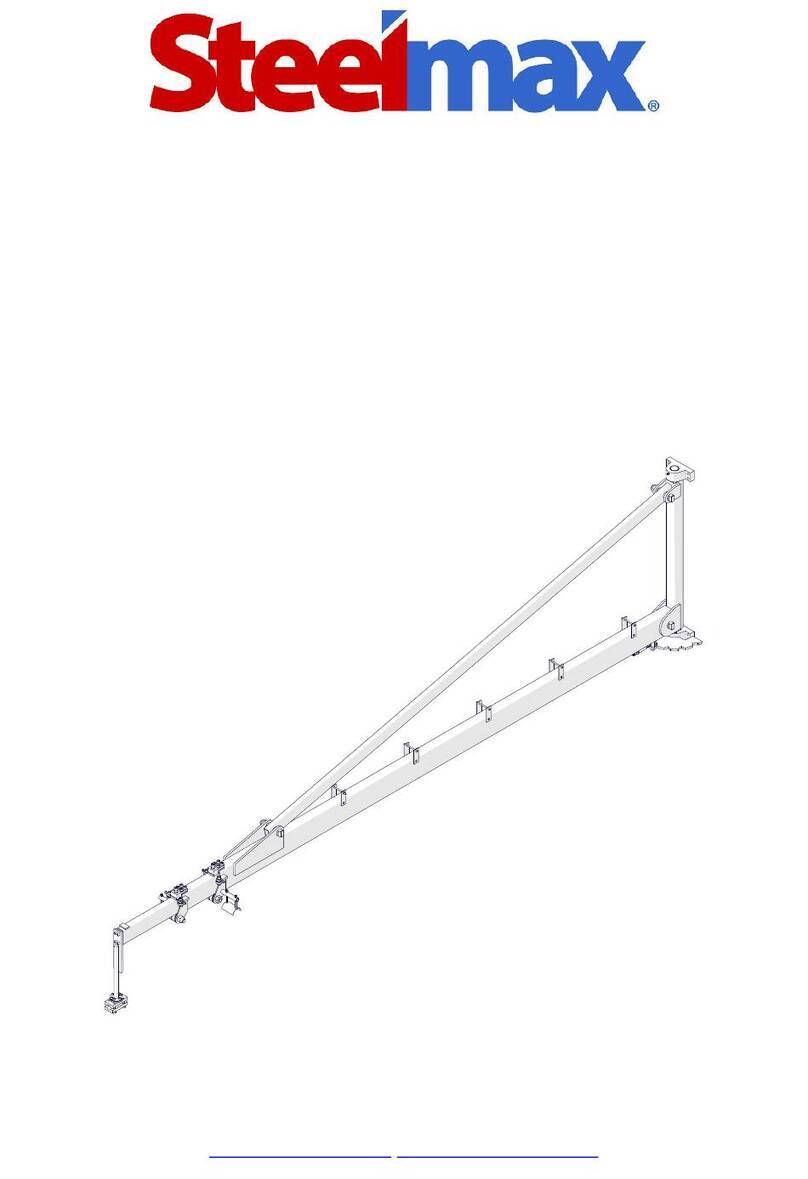
SteelMax TLB6000 User manual

The tools of innovation.
801 W. Mineral Ave. Suite 103
Littleton, CO 80120
303-690-9146 FAX 303 – 690 – 9172
www.steelmax.com [email protected]
OPERATOR’S MANUAL
TELESCOPIC WIRE FEEDER BOOM
T
TL
LB
B6
60
00
00
0,
,
T
TL
LB
B8
80
00
00
0

Contents
1. GENERAL INFORMATION ............................................................................................... 3
1.1. Application ................................................................................................................. 3
1.2. Technical data............................................................................................................ 3
1.3. Dimensions ................................................................................................................ 4
1.3.1. TLB6000......................................................................................................... 4
1.3.2. TLB8000......................................................................................................... 4
1.4. Reach and work area................................................................................................. 5
1.4.1. TLB6000......................................................................................................... 5
1.4.2. TLB8000......................................................................................................... 6
1.5. Design ....................................................................................................................... 7
2. SAFETY PRECAUTIONS.................................................................................................. 8
3. STARTUP AND OPERATION ........................................................................................... 9
3.1. Installing..................................................................................................................... 9
3.2. Operating ..................................................................................................................10
3.3. Maintaining ...............................................................................................................11
4. EXPLODED VIEWS AND PARTS LISTS .........................................................................12
4.1. TLB6000 ...................................................................................................................12
4.2. TLB8000 ...................................................................................................................16
5. DECLARATION OF CONFORMITY .................................................................................20
6. WARRANTY CARD..........................................................................................................22

TLB6000/TLB8000
TLB6000/TLB8000 Operator’s Manual
3
1. GENERAL INFORMATION
1.1. Application
The telescopic wire feeder boom is designed to hang and move a wire feeder.
1.2. Technical data
TLB6000
TLB8000
Reach
106–236″ (2700–6000 mm) 128–304″ (3251-7729 mm)
Rotation angle
0–180°
0–180°
Maximum load (feeder, wire)
110 lbs (50 kg) 110 lbs (50 kg)
Minimum dimensions 106″ × 47″ × 11″
2700 × 1206 ×287 mm
128″ × 47″ × 11″
3251 × 1206 ×287 mm
Maximum dimensions 236″×47″ × 11″
6000 × 1206 × 287 mm
304″ × 47″ ×11″
7729 x 1206 x 287 mm
Weight
216 lbs (98 kg) 265 lbs (120 kg)

TLB6000/TLB8000
TLB6000/TLB8000 Operator’s Manual
4
1.3. Dimensions
1.3.1. TLB6000
1.3.2. TLB8000
38″ (970
mm)
11″ (287 mm)
47" (1206 mm)
12″ (306 mm)
38″ (970 mm)
11″ (287 mm)
47″ (1206 mm)
12″ (306 mm)

TLB6000/TLB8000
TLB6000/TLB8000 Operator’s Manual
5
1.4. Reach and work area
1.4.1. TLB6000
Center of rotation
Minimum reach
Maximum reach
106″ (2700 mm )
236″ (6000 mm)
236″ (6000 mm)
106″ (2700 mm)
Reach
Work area

TLB6000/TLB8000
TLB6000/TLB8000 Operator’s Manual
6
1.4.2. TLB8000
Center of rotation
Minimum reach
Maximum reach
128″ (3251 mm)
304″ ( 7729 mm)
304″ (7729 mm)
128″ (3251 mm )
Reach
Work area

TLB6000/TLB8000
TLB6000/TLB8000 Operator’s Manual
7
1.5. Design
Wire feeder holder
Cable holder
Hinge
Adjustment screw
Movable arm

TLB6000/TLB8000
TLB6000/TLB8000 Operator’s Manual
8
2. SAFETY PRECAUTIONS
1. Before use, read this operator’s manual and complete a training in occupational
safety and health.
2. Use the boom only in applications specified in this operator’s manual.
3. Make sure that the boom has allparts and they are genuine and fully operational.
4. The work area must be large enough to allow the boom to be easily positioned
in the range specified in the technical data
5. Keep the work area well-lit, clean, and free of obstacles. Make sure that access to
the work area is easyand safe.
6. Install the boom so that the section between the hinges isvertical.
7. Install the boom with eight screws and nuts specified in this operator’s manual.
8. Do not try to position the boom outside the reach specified in the technical data.
9. Do not hang a load larger than specified in the technical data.
10. Use a hard hat in the work area.
11. Before use,make sure that the arm clearance is correct. If any armmoves
out without any action from the operator, tighten the adjusting screw to remove
the excessive clearance.
12. Repaironlyin a service center appointed by the seller.

TLB6000/TLB8000
TLB6000/TLB8000 Operator’s Manual
9
3. STARTUP AND OPERATION
3.1. Installing
Be careful and use correct means (platforms, cranes) to ensure safety. Install the
boom so that the section between the hinges is vertical. Attach the boom with eight
M12 screws (DIN931, 10.9 grade) and M12 nuts (DIN985, 10.9 grade).

TLB6000/TLB8000
TLB6000/TLB8000 Operator’s Manual
10
3.2. Operating
Use the 6 mm hex wrench to loosen four screws. Then put the handle of the wire
feeder into the holder and tighten.
Move out the arms of the boom to the required distance. If any arm moves out with-
out any action from the operator, use the 10 mm hex wrench to tighten the adjusting
screw to remove the excessive clearance.
Adjustment screw

TLB6000/TLB8000
TLB6000/TLB8000 Operator’s Manual
11
3.3. Maintaining
At intervals of six months, apply a sufficient quantity of grease into the grease nipples.
Grease nipple

TLB6000/TLB8000
TLB6000/TLB8000 Operator’s Manual
12
4. EXPLODED VIEWS AND PARTS LISTS
4.1. TLB6000

TLB6000/TLB8000
TLB6000/TLB8000 Operator’s Manual
13
29
30
31
33
32
3
11
10
2
9
5
6
8
7
4
1
15
14
43
13
47
29
28
44
26
25
27
23
24
22
21
20
19
18
17
16
12

TLB6000/TLB8000
TLB6000/TLB8000 Operator’s Manual
14
39
34
46
48
42
41
40
38
37
45
36
35
ITEM
PART NUMBER
DESCRIPTION
Q-TY
1
ZWS-0429-02-01-00-0
HINGE
1
2
SMW-000001
GREASE NIPPLE
2
3
ZWS-0429-02-00-00-0
BOTTOM HINGE
1
4
WSP-0569-01-01-00-0
BRACKET II
1
5
BLD-0429-01-02-00-0
LOCK
1
6
SPR-0271-02-02-03-0
SPRING
1
7
PDK-000118
ROUND WASHER 13
2
8
NKR-000003
HEX NUT M12
2
9
LOZ-000153
BALL BEARING 12X37X12
5
10
PDK-000053
SPRING WASHER 12.2
1
11
SRB-000308
HEX SOCKET HEAD CAP SCREW M12x35
1
12
SRB-000426
HEX SOCKET HEAD CAP SCREW M12x20
2
13
NKR-000029
LOW HEX NUT M12
1
14
SRB-000046
HEX SOCKET HEAD CAP SCREW M10x25
8
15
PDK-000052
SPRING WASHER 10.2
12
16
HML-0429.06.01.00.0
BRAKE
2
17
SPR-0152-02-02-05-0
SPRING 8x14.5x0.8
2
18
DCS-0429-06-02-00-0
CLAMP
2
19
WKL-0429-06-04-00-0
INSERT
2
20
TLM-0429-06-03-00-0
DAMPER
4

TLB6000/TLB8000
TLB6000/TLB8000 Operator’s Manual
15
ITEM
PART NUMBER
DESCRIPTION
Q-TY
21
SRB-000048
HEX SOCKET HEAD CAP SCREW M10x35
4
22
PDK-000026
ROUND WASHER 10.5
8
23
SRB-000114
HEX SOCKET HEAD CAP SCREW M6x20
4
24
NKR-000017
HEX NUT M6
12
25
NKR-000096
HEX NUT M20
2
26
PLY-0428-11-02-00-0
CARRIAGE PLATE
2
27
LOZ-000154
BALL BEARING 10X30X9
4
28
PDK-000148
ROUND WASHER 21
18
29
LOZ-000065
BALL BEARING 20X47X16
8
30
PRS-000011
EXTERNAL RETAINING RING 20z
4
31
PDK-000219
WASHER 20x28x0.5
4
32
SWR-0429-03-02-00-0
BOLT
2
33
WSP-0569-02-01-00-0
BRACKET I
1
34
SWR-0429-04-02-00-0
BOLT
2
35
WSP-0569-03-01-00-0
BRACKET II
1
36
SRB-000105
HEX SOCKET HEAD CAP SCREW M6x14
6
37
PKR-0428-12-02-00-0
COVER
2
38
TLJ-0428-12-01-03-0
SLEEVE
1
39
UCW-0428-12-04-00-0
UPPER HOLDER
1
40
UCW-0428-12-03-03-0
LOWER HOLDER
1
41
PDK-000051
SPRING WASHER 8.2
4
42
SRB-000157
HEX SOCKET HEAD CAP SCREW M8x40
4
43
SRB-000193
FULL THREAD HEX HEAD SCREW M20x90
2
44
SRB-000137
HEX SOCKET HEAD CAP SCREW M6x70
4
45
PDK-000046
SPRING WASHER 6.1
6
46
PDK-000218
WASHER 12x18x0.5
4
47
NKR-000002
HEX NUT M10
4
48
PRS-000003
EXTERNAL RETAINING RING 12z
4

TLB6000/TLB8000
TLB6000/TLB8000 Operator’s Manual
16
4.2. TLB8000

TLB6000/TLB8000
TLB6000/TLB8000 Operator’s Manual
17
29
30
31
33
32
3
11
10
2
9
5
6
8
7
4
1
15
14
43
13
47
29
28
44
26
25
27
23
24
22
21
20
19
18
17
16
12

TLB6000/TLB8000
TLB6000/TLB8000 Operator’s Manual
18
39
34
46
48
42
41
40
38
37
45
36
35
ITEM
PART NUMBER
DESCRIPTION
Q-TY
1
ZWS-0429-02-01-00-0
HINGE
1
2
SMW-000001
GREASE NIPPLE
2
3
ZWS-0429-02-00-00-0
BOTTOM HINGE
1
4
WSP-0429-01-01-00-0
BRACKET II
1
5
BLD-0429-01-02-00-0
LOCK
1
6
SPR-0271-02-02-03-0
SPRING
1
7
PDK-000118
ROUND WASHER 13
2
8
NKR-000003
HEX NUT M12
2
9
LOZ-000153
BALL BEARING 12X37X12
5
10
PDK-000053
SPRING WASHER 12.2
1
11
SRB-000308
HEX SOCKET HEAD CAP SCREW M12x35
1
12
SRB-000426
HEX SOCKET HEAD CAP SCREW M12x20
2
13
NKR-000029
LOW HEX NUT M12
1
14
SRB-000046
HEX SOCKET HEAD CAP SCREW M10x25
8
15
PDK-000052
SPRING WASHER 10.2
12
16
HML-0429.06.01.00.0
BRAKE
2
17
SPR-0152-02-02-05-0
SPRING 8x14.5x0.8
2
18
DCS-0429-06-02-00-0
CLAMP
2
19
WKL-0429-06-04-00-0
INSERT
2
20
TLM-0429-06-03-00-0
DAMPER
4

TLB6000/TLB8000
TLB6000/TLB8000 Operator’s Manual
19
ITEM
PART NUMBER
DESCRIPTION
Q-TY
21
SRB-000048
HEX SOCKET HEAD CAP SCREW M10x35
4
22
PDK-000026
ROUND WASHER 10.5
8
23
SRB-000114
HEX SOCKET HEAD CAP SCREW M6x20
4
24
NKR-000017
HEX NUT M6
12
25
NKR-000096
HEX NUT M20
2
26
PLY-0428-11-02-00-0
CARRIAGE PLATE
2
27
LOZ-000154
BALL BEARING 10X30X9
4
28
PDK-000148
ROUND WASHER 21
18
29
LOZ-000065
BALL BEARING 20X47X16
8
30
PRS-000011
EXTERNAL RETAINING RING 20z
4
31
PDK-000219
WASHER 20x28x0.5
4
32
SWR-0429-03-02-00-0
BOLT
2
33
WSP-0429-03-01-00-0
BRACKET I
1
34
SWR-0429-04-02-00-0
BOLT
2
35
WSP-0429-04-01-00-0
BRACKET II
1
36
SRB-000105
HEX SOCKET HEAD CAP SCREW M6x14
6
37
PKR-0428-12-02-00-0
COVER
2
38
TLJ-0428-12-01-03-0
SLEEVE
1
39
UCW-0428-12-04-00-0
UPPER HOLDER
1
40
UCW-0428-12-03-03-0
LOWER HOLDER
1
41
PDK-000051
SPRING WASHER 8.2
4
42
SRB-000157
HEX SOCKET HEAD CAP SCREW M8x40
4
43
SRB-000193
FULL THREAD HEX HEAD SCREW M20x90
2
44
SRB-000137
HEX SOCKET HEAD CAP SCREW M6x70
4
45
PDK-000046
SPRING WASHER 6.1
6
46
PDK-000218
WASHER 12x18x0.5
4
47
NKR-000002
HEX NUT M10
4
48
PRS-000003
EXTERNAL RETAINING RING 12z
4

TLB6000/TLB8000
TLB6000/TLB8000 Operator’s Manual
20
5. DECLARATION OF CONFORMITY
Declaration of Conformity
PROMOTECH sp. z o.o.
ul. Elewatorska 23/1
15-620 Białystok
Poland
We declare with full responsibility that:
Telescopic wire feeder boom TLB6000
is manufactured in accordance with the following standards:
•EN ISO 12100:2010
•ISO 12482-1:1999
and satisfies the regulations of the guideline 2006/42/EC.
Person authorized to compile the technical file:
Wiktor Marek Siergiej, ul. Elewatorska 23/1, 15-620 Białystok, Poland
Białystok, 2 March 2021 ___________________________
Wiktor Marek Siergiej
CEO
This manual suits for next models
1
Table of contents
Other SteelMax Farm Equipment manuals
