SteelMax SM-WFB-TLB6000 User manual


Contents
1. GENERAL INFORMATION ................................................................................................3
1.1. Application ..................................................................................................................3
1.2. Technical data.............................................................................................................3
1.3. Design ........................................................................................................................3
1.4. Equipment included ....................................................................................................4
1.5. Dimensions .................................................................................................................5
1.6. Reach .........................................................................................................................6
2. SAFETY PRECAUTIONS...................................................................................................7
3. STARTUP AND OPERATION ............................................................................................8
3.1. Assembling the frame .................................................................................................8
3.2. Installing the cable holders..........................................................................................9
3.3. Installing the wire feeder holder ................................................................................10
3.4. Installing the boom....................................................................................................10
3.5. Installing the wire feeder ...........................................................................................12
3.6. Boom positioning ......................................................................................................13
3.7. Maintenance .............................................................................................................14
4. ACCESSORIES ...............................................................................................................15
4.1. R type wire feeder holder..........................................................................................15
4.2. L type wire feeder holder...........................................................................................15
4.3. Free-standing pillar ...................................................................................................16
5. DECLARATION OF CONFORMITY .................................................................................19
6. WARRANTY CARD..........................................................................................................20

SM-WFB-TLB6000, SM-WFB-TLB8000
SM-WFB-TLB6000, SM-WFB-TLB8000 Operator’s Manual
3
1. GENERAL INFORMATION
1.1. Application
This boom is designed to hang and move the welding wire feeder. The boom is
designed for use by the professional operator only.
1.2. Technical data
Model
Reach
Rotation angle
Maximum load
Weight
SM-WFB-TLB6000 101 31/32–237 51/64″0–180° 110 lbs (50 kg) 236 lbs
(107 kg)
SM-WFB-TLB8000 132 43/64–307 3/32″0–180° 110 lbs (50 kg) 291lbs
(131 kg)
1.3. Design
Fig. 1. Design
Assemblable frame
Adjustment screw
Cable holder
Movable arm
Wire feeder holder
L type
(accessory)
R type
Top hinge
Bottom hinge
Cable support
(3370–7800 mm)
(2590-6040 mm)

SM-WFB-TLB6000, SM-WFB-TLB8000
SM-WFB-TLB6000, SM-WFB-TLB8000 Operator’s Manual
4
1.4. Equipment included
1
Frame parts
1 set
2
Pin
3 units
3
Washer
3 units
4
M24 nut
3 units
5
Cable holder
2 units
6
Top hinge
1 unit
7
Bottom hinge
1 unit
8
R type wire feeder holder
1 unit
9
M8x25 screw
4 units
–
Operator’s manual
1 unit
Fig. 2. Equipment included
1
2
3
4
5
6
7
8
9
SM-WFB-TLB6000, SM-WFB-TLB8000
SM-WFB-TLB6000, SM-WFB-TLB8000 Operator’s Manual
5
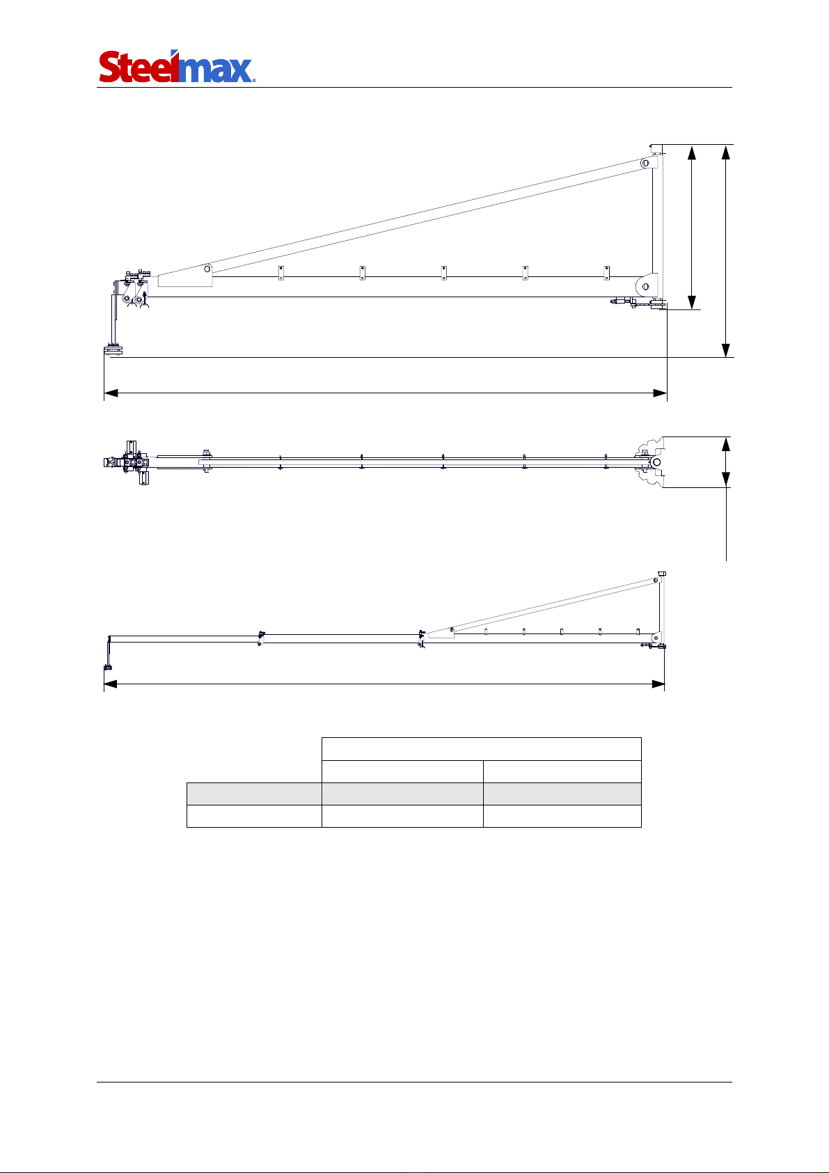
1.5. Dimensions
Dimensions
L
MIN
L
MAX
SM-WFB-TLB6000 101 31/32″ (2590 mm) 237 51/64″ (6040 mm)
SM-WFB-TLB8000 132 43/64″ (3370 mm) 307 3/32″ (7800 mm)
Fig. 3. Dimensions of boom
49 7/32″ (1250 mm)
LMIN
L
MAX
38 3/16″ (970 mm)
(290 mm )
11 27/64"
Retracted boom
Extended boom

SM-WFB-TLB6000, SM-WFB-TLB8000
SM-WFB-TLB6000, SM-WFB-TLB8000 Operator’s Manual
6
1.6. Reach
Use the boom in the reach shown in the figure below!
Fig. 4. Reach
Frame center of rotation
Frame
Movable arms
Reach
Steel element to which the
boom is installed
MIN MAX
SM-WFB-TLB6000
101 31/32″ (2590 mm) 237 51/64″ (6040 mm)
SM-WFB-TLB6000
132 43/64″ (3370 mm) 307 3/32″ (7800 mm)
180⁰
MIN
MAX

SM-WFB-TLB6000, SM-WFB-TLB8000
SM-WFB-TLB6000, SM-WFB-TLB8000 Operator’s Manual
7
2. SAFETY PRECAUTIONS
1. Before use, read this operator’s manual and complete a training in occupational
safety and health.
2. Use only in applications specified in this operator’s manual.
3. Make sure that the boom has all parts and they are genuine and not damaged.
4. Use only the parts included with the boom for assembly.
5. Make sure the boom is correctly assembled.
6. Keep the work area well-lit, clean, and free of obstacles. Make sure that access to
the work area is easy and safe.
7. Make sure that the work area is larger than the reach specified in this operator's
manual.
8. Do not use the boom outside the reach specified in this operator’s manual.
9. Install the boom so that the section between the hinges is vertical in the side and
front planes.
10. Install the boom to steel elements with proper load-bearing capacity.
11. Install the boom with eight screws and nuts specified in this operator’s manual.
12. Do not hang a load larger than specified in the technical data.
13. Use a helmet when installing, operating and being in the work area.
14. Make sure that the arm backlash is correct. If any arm moves out without any action
from the operator, tighten the adjusting screw to remove the excessive backlash.
15. Use with a wire feeder powered by no more than 48 volts DC.
16. Repairs can only be carried out by the service specified by the seller.
17. Work at heights can only be carried out by a person with appropriate permits.
SM-WFB-TLB6000, SM-WFB-TLB8000
SM-WFB-TLB6000, SM-WFB-TLB8000 Operator’s Manual
8
3. STARTUP AND OPERATION
Be careful and use correct means (platforms, cranes) to ensure safety.
Wear head protection when installing, operating or whenever in the
work area.
You can only do work at heights if you have appropriate permits.
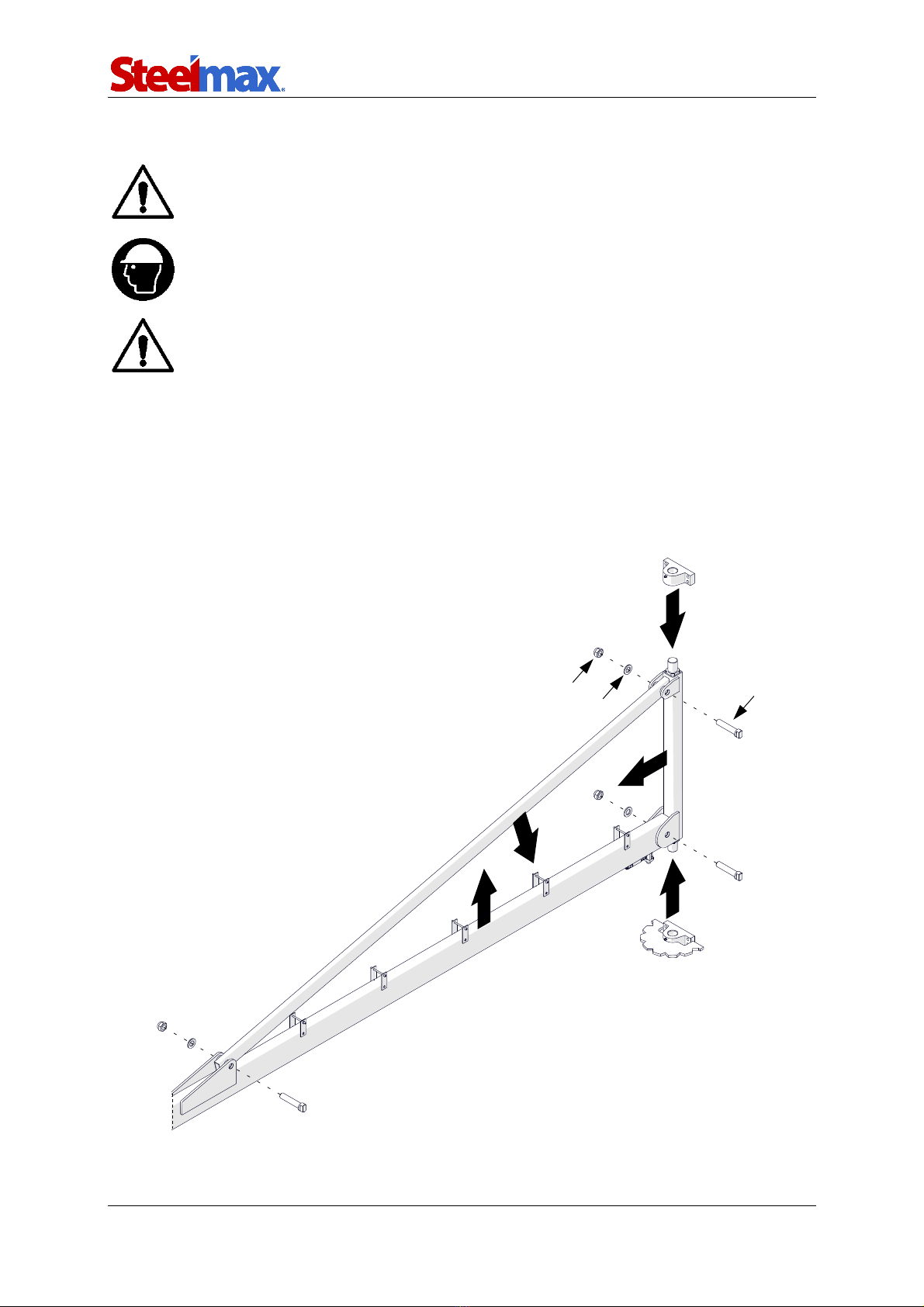
3.1. Assembling the frame
Assemble the frame parts (1, 2, 3) as shown in the figure below using pins (4), washers
(5) and M24 nuts (6). Tighten the nuts with a 36 mm wrench (not included). Place the
top and the bottom hinge on the frame (7).
Fig. 5. Assembling the frame
1
2
4
5
6
7
7
3

SM-WFB-TLB6000, SM-WFB-TLB8000
SM-WFB-TLB6000, SM-WFB-TLB8000 Operator’s Manual
9
3.2. Installing the cable holders
Install the cable holder (1) with two M6x70 screws (2) and tighten with four M6 nuts (3).
Leave space for the cable (4).
Fig. 6. Installing the cable holders
3
1
2
4
SM-WFB-TLB6000, SM-WFB-TLB8000
SM-WFB-TLB6000, SM-WFB-TLB8000 Operator’s Manual
10
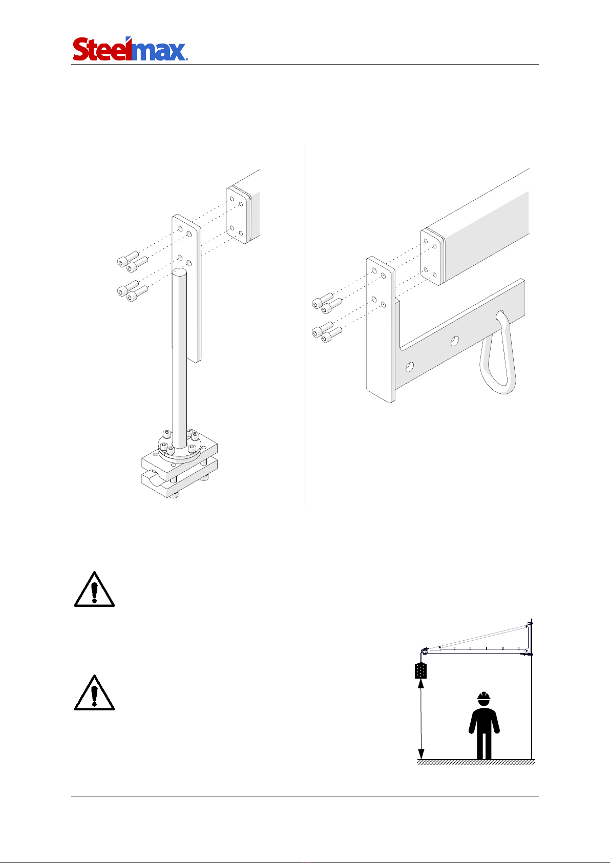
3.3. Installing the wire feeder holder
Using a 6 mm hex wrench (not included) attach the wire feeder holder with four M8x25
screws to the movable arm (1).
R type wire feeder holder L type wire feeder holder (accessory)
Fig. 7. Installing the wire feeder holder
3.4. Installing the boom
Only install the boom to steel elements.
Install the boom at height (H) safe for
people nearby.
1
1
H

SM-WFB-TLB6000, SM-WFB-TLB8000
SM-WFB-TLB6000, SM-WFB-TLB8000 Operator’s Manual
11
Following the picture below, prepare the hinges mounting holes suitable for M12 screw.
Include that the section between the hinges must be vertical in the front (1, 2)
and side (3) planes. When installing, use a level or other tool that allows for precise
vertical and horizontal alignment.
Fig. 8. Installing the boom vertically in the front and side planes
(130 mm)
5 1/8″
26 mm
1 1/32″
~ 35 13/64″ (894 mm)
3
2
1
(26 mm)
1 1/322″

SM-WFB-TLB6000, SM-WFB-TLB8000
SM-WFB-TLB6000, SM-WFB-TLB8000 Operator’s Manual
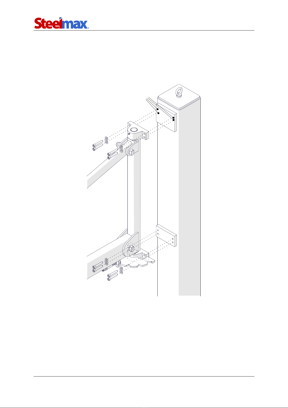
12
Use eight M12 screws (DIN931 or DIN912, class 10.9 - not included) and M12 nuts
(DIN985, class 10.9 - not included) and optional washers (DIN125 D13 – not included)
(1) suitable for the type of steel element.
Fig. 9. Installing the boom
3.5. Installing the wire feeder
R type wire feeder holder
L type wire feeder holder
(accessory)
Using a 6 mm hex wrench (not included),
loosen four screws (1). Insert the wire feeder*
to the holder. Tighten the screws.
Insert the hook (1) into the selected
hole of the holder (2
). Then attach
the wire feeder* to the hook.
Fig. 10. Installing the wire feeder
* Install the wire feeder as recommended by its manufacturer using the
element (handle, hook, etc.) designed for this purpose.
1
1
2
1

SM-WFB-TLB6000, SM-WFB-TLB8000
SM-WFB-TLB6000, SM-WFB-TLB8000 Operator’s Manual
13
3.6. Boom positioning
Rotate the frame and extend the movable arms to the required position.
If any arm moves out without any action from the operator, use the 10 mm hex
wrench (not included) to tighten the adjusting screw (1) to remove the excessive
backlash.
Be careful – depending on the dimensions of the wire feeder and steel
element to which boom is installed, a collision may occur!
Do not allow for uncontrolled rotation of the frame and extension of mov-
able arms!
Fig. 11. Boom positioning
1

SM-WFB-TLB6000, SM-WFB-TLB8000
SM-WFB-TLB6000, SM-WFB-TLB8000 Operator’s Manual
14
3.7. Maintenance
Every six months apply a sufficient quantity of grease into the lubrication points.
Fig. 12. Boom maintenance
Lubrication point

SM-WFB-TLB6000, SM-WFB-TLB8000
SM-WFB-TLB6000, SM-WFB-TLB8000 Operator’s Manual
15
4. ACCESSORIES
4.1. R type wire feeder holder
4.2. L type wire feeder holder
Part number:
MCW-0732-08-00-00-0
(4 screws M8x25 included)
Part number:
MCW-0732-09-00-00-0
(4 screws M8x25 included)

SM-WFB-TLB6000, SM-WFB-TLB8000
SM-WFB-TLB6000, SM-WFB-TLB8000 Operator’s Manual
16
4.3. Free-standing pillar
Designed to install the boom on it. Height: 3 m (9.84 ft).
1
Eyebolt
1 unit
2
Washer
8 units
3
M12x65 screw
8 units
4
Anchor rod M16 – 190 mm (7 31/64″)
8 units
5
3/64″ (1 mm)thick special washer
16 units
6
1/64″ (0.5 mm)thick special washer
16 units
7
1/64″ (0.2 mm) thick special washer
16 units
8
Free-standing pillar
1 unit
1
2
3
4
5
6
7
8
Part number:
SLP-0429-07-00-00-0

SM-WFB-TLB6000, SM-WFB-TLB8000
SM-WFB-TLB6000, SM-WFB-TLB8000 Operator’s Manual
17
Screw the eyebolt into the hole (1). Transport the pillar using transport means. Set on
the floor and level using special
with a grade of at least C20/25
washers (2). Anchor the pillar to floor made of concrete
and a minimum thickness of 6 19/64" (160mm) using
eight anchor rods (3) and injection resin* (not included). Follow the recommendations
of the resin manufacturer. The spacing of the anchor holes is shown below.
* recommended resin is TRUTEX TCM420 PRO
1
(Min. 125 mm)
4 59/64″
90⁰
2
3
(340 mm)
6 11/16″ (170 mm)
13 25/64″
(340
mm)
13 25/64″
6 11/16″ (170 mm)
Ø(18 mm)
45/64″
SM-WFB-TLB6000, SM-WFB-TLB8000
SM-WFB-TLB6000, SM-WFB-TLB8000 Operator’s Manual
18
To install the boom, attach the bottom hinge to the mounting holes of the pillar with
four washers and M12x65 screws (4) using a 10 mm hex wrench (not included). Make
four M12 threaded holes for top hinge (5). Then attach the top hinge with four washers
and M12x65 screws (6).
4
5
6

SM-WFB-TLB6000, SM-WFB-TLB8000
SM-WFB-TLB6000, SM-WFB-TLB8000 Operator’s Manual
19
5. DECLARATION OF CONFORMITY
Declaration of conformity
PROMOTECH sp. z o.o.
ul. Elewatorska 23/1
15-620 Białystok, Poland
We declare with full responsibility that:
Telescopic wire feeder boom SM-WFB-TLB6000, SM-WFB-TLB8000
is manufactured in accordance with the following standards:
•EN ISO 12100: 2010
•ISO 12482-1: 1995
and satisfies regulations of the guidelines: 2006/42/EC
Person authorized to compile the technical file:
Wiktor Marek Siergiej, ul. Elewatorska 23/1, 15-620 Białystok, Poland
Białystok, 16 February 2023 ___________________________
Wiktor Marek Siergiej
CEO

SM-WFB-TLB6000, SM-WFB-TLB8000
SM-WFB-TLB6000, SM-WFB-TLB8000 Operator’s Manual
20
6. WARRANTY CARD
Warranty card no.............
.......................................................................... in the name of Manufacturer warrants
the*:
Telescopic wire feeder boom: SM-WFB-TLB6000, SM-WFB-TLB8000
* mark correct
to be free of defects in material and workmanship under normal use for a period of 12
months from the date of sale.
This warranty does not cover damage or wear that arise from misuse, accident,
tampering, or any other causes not related to defects in workmanship or material.
Serial number ................................................................................................................
Date of sale ...................................................................................................................
Signature and stamp of the seller..................................................................................
0.02 / 05 September 2023
WE RESERVE THE RIGHT TO MAKE CHANGES IN THIS MANUAL WITHOUT NOTICE
This manual suits for next models
1
Table of contents
Other SteelMax Farm Equipment manuals

Popular Farm Equipment manuals by other brands


horsch
horsch Sprinter 18 NT operating instructions

Degelman
Degelman PRO-TILL 10/13 quick start guide

MS Schippers
MS Schippers Automix 2.0 Operating and safety instructions

Walker
Walker A10 Operator's manual

SAW TRAX
SAW TRAX Scoop Dolly instruction manual

Raven
Raven SmartBoom RoGator 864 installation manual

AHRENS AGRICULTURAL INDUSTRIES
AHRENS AGRICULTURAL INDUSTRIES E-Fount MIRACO 3410-4E installation instructions

Agriweld
Agriweld DIRECT DRIVE Series Operator's manual

LYSON
LYSON W4075 manual

Land Pride
Land Pride DB2660 Operator's manual

Bro-Tek
Bro-Tek Thumb Instruction & safety manual

GREAT PLAINS
GREAT PLAINS 706NT instructions