STEELTEC 52CC User manual


2
STEELTEC MULTITOOL
CONTENTS OF BOOKLET
Warnings Check List Page 3
What Is In Your Box/Assembly Page 4
Blade Assembly/Air Filter AƩachment Page 5
Blade Assembly/Air Filter AƩachment Page 6
Pole Assembly And AƩaching Page 7
OperaƟng The Pruner/Installing The Bar And Chain Page 8
AdjusƟng The Chain Page 9
Chain Oiler/Filling The Oil Resvoir/AdjusƟng The Oil Flow Rate Page 10
Typical ApplicaƟons Standard Cut Page 11
Steps For StarƟng Your Machine Page 12
How To Mix The Fuel Page 13
AdjusƟng The Idle Screw On Your Machine/Fuel Mixture Screw Adjustment Page 14
Maintenance On Your Pole Pruner Page 15
AƩaching Blades/AƩaching Nylon CuƩer And Bracket Onto Guard Page 16
How To Open And Close Whipper Snipper Head Page 17
Cuƫng OperaƟon/Maintenance Of Your Machine Page 18
Hedge Trimmer AƩachments Page 19
Installing The Hedge Trimmer Cuƫng Assembly/AdjusƟng The
ArƟculated Hedgetrimmer Cuƫng Assembly Page 20
AdjusƟng The Hedgetrimmer Cuter Assembly For Desired Cuƫng Angles/AdjusƟng
The CuƩer Assembly For Storage Or TransportaƟon/How To Use Hedgetrimmer AƩachment Page 21
Daily Maintenance Page 22

3
BEFORE USING THIS UNIT:
Please Read the Operator’s manual carefully.
Check that the Cung equipment is correctly assembled (please
read and follow instrucons on Page 5)
Start the Unit and check the carbureor adjustment (Please check
Page 11 for this step if needed)
Always Wear Eye, Head and Ear Protectors when
Using This Unit.
Keep all Children, bystanders and helpers 15m (50) away from
Unit. If anyone approaches you, stop the engine and cung
aachment immediately.
Gloves, Safety Goggles and ear muffs and Slip and Sturdy Footwear
should be worn at all mes when operang
tools or Machinery.
ALWAYS MAINTAIN THIS MULTITOOL ACCORDING TO THE OWNER’S
MANUAL AND FOLLOW THE RECOMMENDED SCHEDULED
MAINTENANCE.
NEVER MODIFY OR DISABLE ANY OF THE POLE PRUNER’S
SAFETY DEVICES.
ALWAYS USE GENUINE PARTS AND ACCESSORIES WHEN REPAIRING
OR MAINTAINING THIS MACHINE. DO NOT MAKE UNAUTHORIZED
MODIFICATIONS OR SUBSTITUTIONS TO THE GUIDE BAR OR CHAIN
NEVER ALLOW THE ENGINE TO RUN AT HIGH RPM WITHOUT A
LOAD. DOING SO COULD DAMAGE
THE ENGINE.
WHEN TRANSPORTING THE PRUNER IN A VEHICLE, TIE IT DOWN
SECURELY TO PREVENT DAMAGE AND FUEL SPILLAGE.
ALWAYS CLEAR YOUR WORK AREA OF TRASH OR HIDDEN DEBRIS
TO HELP ENSURE GOOD FOOTING.
KEEP THE SAW CHAIN SHARP AND PROPERLY ADJUSTED
KEEP THE PRUNER AS CLEAN AS POSSIBLE. KEEP IT FREE OF LOOSE
VEGETATION, MUD ETC.
15m (50ft)

4
ACCESSORIES:
G1. 12” Chain cover
G2. 12” Guide Bar
G3. 12” Chain
J2. Poles
2,3 or 4 Poles vary depending
on product.
M. Hedge Trimmer
H. Coupler
K. Chain Head
N. Brush Cuer
i1. Airfilter
D. Hex screw for Air filter on the motor
L. Shoulder Strap
O. D Handle
G3
G1
G2
H
J2
J2
M
K
N
O
P
L
H
i
D
G2
G
G
G
G
G
G
G
G
G
J2
J2
J
2
J
J
M
M
M
M
M
M
M
M
H
H
K
K
K
K
K
K
K
K
N
N
N
N
N
N
N
N
N
i
i
i
L
STANDARD COMPONENTS
A. 4x Hex Screws & Nuts (Handle)
B. Nylon Cuer
C. Nylon Cuer Scew
D. 2 plasc es
E. Hex for Air filter on the motor
F. Tools
WHAT IS IN YOUR BOX
B
C
E
D D
F2 F2
F2
A
A
F
F
F

5
HANDLE ASSEMBLY:
STEP 1
Rubber sleeve should already be on pole.
STEP 4
Place the top segment of the handle as seen above.
STEP 2
Insert nuts into the boom segments of the handle as
seen above.
STEP 3
Place the boom segment of the handle into the groove
of the rubber sleeve.
STEP 5
Insert hex screws provided.

6
D
i
ATTACHING THE AIR FILTER TO YOUR MACHINE:
BLADE ASSEMBLY
EIGHT TOOTH
FOURTY TOOTH
THREE TOOTH
FOUR TOOTH
(please note that quanes of blades will vary per model - 5in1, 6in1, 7in1, 8in1)
TWO TOOTH
PLASTEC

7
POLE ASSEMBLY & ATTACHING
1ΉAach Coupler/Joiner (H) to the end of the pole that does
not have the pre-drilled inxdex hole. Phsical holes are
not neccessary for aaching the joiner. Screws on
coupler or joiner are pressure aached against pole.
3ΉPlace pole into joiner with index hole facing upwards.
Adjust/Rotate the hole unl it firmly clicks into place.
2ΉVisible holes at the base of the pole are
4ΉPush down the safety shield firmly unl it locks into
place. Once down ghten the T-handle unl its firm (to
protect the release mechanism).
5ΉRELEASE
Release the safety sheild and push down on the release
clip while gently rotang and removing pole.
H
H
BASE OF POLE
Index hole facing up
TOP OF POLE
Coupler Attaches this end
SCREWS
Screw in Hex screws until
firm against pole.
H
H
H
H
H
H
H
H
H
H

8
Hook the strap hook to the outer pipe on the sha
of the machine
Wear the strap so that the hook stays at your right hand side.
Adjust the length of the strap so that it is comfortable and at the
correct length whilst operang the pruner.
In emergency situaons unhook the metal clasp, this will release
the machine from the strap.
Please View Mega Machine Warehouse Help Videos For Installation.
of Poles and Starting Sequence For Operation Of This Machine.
OPERATING THE PRUNER
INSTALLING THE BAR AND CHAIN
NEVER ATTEMPT TO INSTALL, REPLACE, OR ADJUST THE CHAIN WITH THE ENGINE RUNNING!
WARNING! THE SAW IS VERY SHARP. WEAR GLOVES TO PROTECT YOUR HANDS WHEN HANDLING.
1ΉUsing the small end of the plug wrench remove sprocket
cover nut (turn counterclockwise to remove).
3ΉInstall the chain loop over the drive links within the guide bar groove, and then align the chain over the drive sprocket.
Make sure the cuer are properly oriented as shown in the picture below.
2ΉPlace the guide bar over the guide bar adjustment stud
on the cung head assembly. Align the chain tension pin
with the hole in the guide bar.
4ΉInstall the sprocket cover over the bar stud.
Using finger-pressure only, install the
sprocket cover nut.

9
IMPORTANT
Proper chain adjustment is essenal for maximum performance, long chain life, and operator safety. Always inspect chain tension before
operang the pole pruner.
1ΉLoosen the sprocket cover nut with a Plug wrench.
2ΉLithe nose of the guide bar while turning the chain tensioning screw
Clockwise to ghten the chain Counterclockwise to loosen the chain.
3ΉPull the Chain by hand along the top of the guide bar several mes from the engine to the bar’s p. The chain should feel sung
but sll pull freely.
4ΉTighten the sprocket cover nut securely while liing the p of the guide bar.
5ΉInspect the chain for correct adjustment (more frequently with a new chain). The chain should feel snug but sll pull freely.
ADJUSTING THE CHAIN
NEVER ATTEMPT TO INSTALL, REPLACE, OR ADJUST THE CHAIN WITH THE ENGINE RUNNING. WARNING! THE SAW CHAIN IS VERY SHARP.
WEAR GLOVES TO PROTECT YOUR HANDS WHEN HANDLING.
CAUTION! A LOOSE CHAIN CAN JUMP OFF THE GUIDE BAR CAUSING DAMAGE TO THE CHAIN AND ASSOCIATED EQUIPMENT. ALWAYS MAKE
SURE THE CHAINS IS PROPERLY ADJUSTED; CHECK MORE OFTEN WHEN YOU ARE BREAKING IN A NEW CHAIN.
10
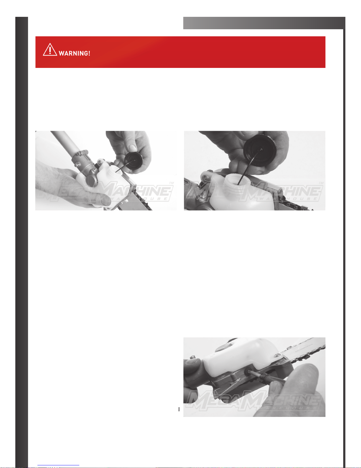
CHAIN OILER
FILLING THE OIL RESEVOIR
The oil reservoir has a capacity sufficient to provide about 40 minutes of cung me (when set to deliver the minimum flow rate)
1ΉPlace the pole pruner on a clean, flat surface with the oil filler cap facing up.
Wipe offany debris from the oil cap and from around the oil filler neck.
2ΉRemove the oil filler cap and fill the reservoir with bar and chain oil, then replace the cap.
3ΉWipe up spilled oil from the unit before restarng the pole pruner.
ADJUSTING OIL FLOW RATE
The guide bar and chain are lubricated automacally by a pump that operates whenever the chain rotates, the pump is set at the factory to
deliver a medium flow rate, but it can be adjusted in the field. A temporary increase in oil flow is oen desireable when cung things like
hardwood or wood with a lot of pitch.
ADJUST THE PUMP AS FOLLOWS:
1ΉStop the engine and make sure the stop switch is in the
STOP posion.
2ΉPlace the unit on it’s side with the oil Reservoir up
3ΉWith a screw driver, push in on the oil flow rate adjusng
screw and turn in the desired direcon (there are
three incremental sengs):
CLOCKWISEͳDECREASE LUBRICATION
COUNTERCLOCKWISEͳINCREASE LUBRICATION
NEVER FILL THE OIL RESERVOIR NOR ADJUST THE OILER WITH THE ENGINE RUNNING.
N

11
TYPICAL APPLICATIONS
STANDARD CUT:
The most convenient working posion is a tool angle of 60O, but any
other angle may be used to suit the situaon concerned.
CUTTING ABOVE OBSTACLE:
Thanks to the unit’s long reach it is possible to prune branches that
are overhanging obstacles, such as rivers or lakes. The tool angle in
this case depends on the posion of the branch.
WORKING TECHNIQUES ΈPLEASE READΉ
RELIEVING CUT:
To avoid tearing the bark, kickback or pinching the bar when pruning
thick branches, always start by performing a relieving cut e.g if the
branch you are cung is around 5 cms thick cut from the lower part
of the branch upwards, then stop and turn the pole pruner on the
other side of the branch downwards cung the branch offthe tree.
FLUSHͳCUTTING THICK BRANCHES:
If branch diameter is more than 10cm (4”), first perform undercut
(3) and cross-cut at a distance (A) of about 25cm (10”) from the final
cut. Than carry out the flush-cut (4), starng with a relieving cut and
finishing with a cross-cut.

12
STEPS FOR STARTING YOUR MACHINE
STEP 1
Mix the 2 stroke fuel to the correct
rao (25:1)-(30:1) and fill the tank.
!SEE BELOW FOR FUEL INFORMATION
STEP 4
Slide the take on switch to the
down posion.
STEP 7
Pull the recoil 2–4 mes. By the fourth
pull, it should sound like the engine is
going to start. Move to Step 8.
STEP 2
Press the fuel bubble 5–7 mes (no
more than 7). Fuel should now fill the tube
next to pump.
STEP 5
Squeeze the top and boom levers
in and hold in firmly (as pictured in 5.2).
STEP 8
Slide the choke down to the boom
posion for the final starng and running
operaon of the machine.
STEP 3
Slide the choke to the up posion.
STEP 6
While holding top lever and boom
lever squeezed in, slide down or push in
the locking switch.
STEP 9
Pull the recoil once again, or unl
the engine starts.
CHOKE SETTINGS
ON POSITION: IS FOR INITIAL STARTING
OFF POSITION: IS FOR THE RUNNING OPERATION OF THE MACHINE

13
HOW TO MIX YOUR FUEL
Common mixtures are 25:1/30:1. If you find your machine is too
smoky please use the higher rao which is 30:1 as seen in diagram C.
WHAT IS 25:1/30:1?
The first part of the formula refers to how many parts of fuel as seen
in diagram A. The second part of the formula refers to how many
parts of oil (diagram B or C). For example, 25 parts of unleaded fuel or
low octane to 1 part of two stroke oil or 30 parts of unleaded or low
octane fuel to 1 part of two stroke oil.
REMEMBER TO MIX WELL (SHAKE BOTTLE)
ONLY USE THIS RECOMMENDED 2 STROKE FUEL MIX WITH A GOOD QUALITY 2 STROKE OIL FROM YOUR LOCAL SUPPLIER, USING A MIX
RATIO OF 25:1/30:1 IN THE MACHINE. UNLEADED OR LOW OCTANE FUEL ANY OTHER FUEL MUST BE USED IN A TWO STROKE MIX. MIX WELL
AS RECOMMENDED. INCORRECT MIX COULD DAMAGE YOUR ENGINE VOIDING YOUR WARRANTY, USE THIS FUEL MIX EVERY TIME YOUR
MACHINE IS IN OPERATION FOR THE BEST DINGO TOOLS PERFORMANCE YOU CAN EXPECT OUT OF YOUR DINGO TOOLS MACHINE.
1
:
25
OIL
600
576.92
500
400
300
200
100
GASOLINE
FULL
1
:
25
OIL
600
576.92
30:1
C
1
:
25
OIL
600
576.92
25:1
BA
1
:
:
:
:
:
:
:
25
25
25
25
2
5
5
25
5
OI
O
O
O
O
O
O
O
L
L
L
L
600
576 92
57
57
7
7
7
57
7
7
6.
6.
.
6.
.
.
92
92
92
9
9
500
25
AT ALL TIMES PLEASE KEEP THE FUEL TANK FULL WHEN IN OPERATION,
“AVOID HAVING THE YOUR ENGINE FINISHING OPERATION FROM FUEL
STARVATION. FUEL TANKS BEING KEPT FULL AT ALL TIMES WILL IMPROVE
YOUR MACHINE PERFORMANCE.
FUEL RUNNING OUT WHILE IN OPERATION MAY DAMAGE YOUR ENGINE,
PLEASE BE SURE TO REFILL THE TANK, KEEPING THE FUEL WELL FILLED
DURING OPERATION IN ASSISTING AND AVOIDING BREAK DOWNS OR
OPERATION INTERRUPTIONS. FUEL TANKS BEING EMPTIED DURING
OPERATION, MAY RISK DEBRIS ALL FOREIGN OBJECTS ENTERING INTO
THE FUEL INTAKE CONFIGURATION SYSTEM CAUSING BLOCKAGES, OVER
HEATING AND EVEN PISTON FAILURE. TO AVOID THESE CIRCUMSTANCES
PLEASE KEEP YOUR FUEL TANK WELL FILLED AT ALL TIMES, AVOIDING
ENGINE BREAKS INCURRED, FROM THE RESULT OF FUEL STARVATION.

14
ADJUSTING IDLE SCREW
ON YOUR MACHINE
If your Idling of your brushcuer needs adjusng e.g it is idling too fast or slow or is cung out please follow the steps below on how to adjust
this on your machine.
When looking down in a birds eye view at the carby or Choke area, at the the top of the Carby where the throle control cable aaches to the
side of the mechanism, you will see a silver screw on the right hand side at the top.
Where the Sliver Screw enters in and the p of the Silver Screw comes out the outer side, you should be able to view when looking at least 3 –
4mm of screw p, turning this screw to the lewill speed up the idle, while turning the silver screw to the right will slow the idle down.
We suggest that you adjust the screw so you may be able to view 3 or 4mm of screw p, if you see more screw p, please back adjust the
screw to this suggested seng and if you are viewing less of the screw p, please adjust the screw so you are able to view more of the p at
least 3 or 4mm of screw p and no more or less.
FUEL MIXTURE SCREW ADJUSTMENT
If your machine is not revving or not running correctly please
adjust the Fuel Mixture Screw with the steps
to the right.
When facing the Carby side of the machine and looking at the
carby on the right hand side of the Carby down near the top of
the fuel tank and infront of the black fuel line in take tube, you
will see a brass screw, this is the fuel mix screw, this adjusts how
much fuel may enter the machine.
To set this screw in the correct posion we need to start the screw at zero first, please turn the brass screw all the way to the right or clock wise
unl it will not turn any further, please try not to over turn it when screwing it all the way in, as when you have reached the end of it’s thread
and if you keep turning it with force, you may snap the screw off.
When you have turned the screw all the way in to the right or clock wise so it can not turn any further this is what we call or state as being
at zero. Now please turn the screw 1 and 1 quarter turns to the leor anclock wise to set it in the correct posion for the fuel intake and
smooth operaon.
*** NOTE ***
If 1 and 1 quarter turns isnt enough as the adjustment has not being successful please start the brass screw back at zero and try
a 1 and half full turns anti clock wise or to the left to set the carby with a little bit more fuel into the machine.

15
MAINTENANCE OF YOUR POLE PRUNER
EVERY 50 HOURS OF OPERATION (more frequently in dusty or dirty condions)
1) Remove and clean the cylinder cover and clean dirt and debris from the cylinder cooling fins.
2) Remove the sprocket cover and inspect the sprocket for
excessive dirt, debris, or wear. Remove the guide
bar and clean out the guide bar groove. If the sprocket
is excessively worn, replace it with a new one.
3) Lubricate the gearcase. To perform this operaon, first
remove the gearcase from the upper outer tube
as follows.
4) Follow “Disassembling the pole secons” secon to remove the upper tube from the gearcase.
5) Using a lever-type grease gun, pump lithium-base grease (about 10 grams) into the grease fing unl you see old grease being
purged from the gearcase, which can be seen in the outer tube cavity. Clean up excess grease, then reassemble the gearcase
onto the outer tube.

16
ATTACHING BLADES
ATTACHING NYLON CUTTER AND BRACKET ONTO GUARD
STEP 1
Remove top nut, top plate and
resng plate.
STEP 2
Posion center of blade over raised circular
lip (fing into blade.)
STEP 3
Posion 3 (boom plate) onto assembly.
STEP 4
Posion 2 (top plate) onto assembly.
STEP 5
Apply 1 (locking nut) and
turn an-clockwise to lock into posion
(whilst holding the screw driver through
outer and inner index hole on head.)
1
1
1
1
1
2
2
2
2
2
3
3
3
STEP 1
Aach screw into nylon cuer and then screw onto splaer cover
which is the lower outer black part of the guard.
STEP 2
Apply hex screws into bracket and fit bracket and hex screws around
pole into guard. Tighten unl firm.
B
A
1
1
1
1
1
1
1
1
1
2
2
3
2
1
1
1
1
1
1
2
2
2
2
2
2
2
2
2
3

17
HOW TO OPEN WHIPPER SNIPPER HEAD
HOW TO CLOSE WHIPPER SNIPPER HEAD
STEP 1
To aach lid correctly please line up
markers on base and lid.
STEP 4
Line up markers in the appropriate posion
for aachment.
STEP 7
Push down on tab from step 2 while
applying pressure to top and boom.
STEP 2
Push down on tab and Rotate base
clockwise.
STEP 5
Please be sure that the male and famale
connectors are aligned.
STEP 8
Following through from step 7, when tab
has been pushed into lid rotate to lock
into place.
STEP 3
Connue rotaon and seperate lid
from base.
STEP 6
Following through from step 5.
Please see videos on Mega Machine on Changing Whipper Snipper Line or Assembling Whipper Snipper Head.

18
CUTTING OPERATION
Always Cut by Guiding the head from your right to le.
Adjust the idle speed (see page X) for different types of grass you cut e.g cut tough shrubs or weeds at a high idle, and young
grass at a middle speed.
A metal blade cut best up to the point 1/3 from the edge. Use that area for cung shrubs, tough and thick weeds. For cung
young grass, you can use up to 2/3 from the p of the blade.
MAINTENANCE OF MACHINE
GEAR CASE
Please Supply Mul-purpose grease at every 25 hours of use. Remove the cuer holders to arrange for old grease to exsist.
MAITENANCE BEFORE STORAGE
Brushing offdirt from the machine, check damage or slack of each part. If you find out abnormalies,
repair them for the next use.
Extract fuel from the tank, and loose the drain screw of the float cabin to extract fuel, turn on the engine, and leave it running
unl it stops naturally.
Remove the spark plug and put in 1-2cc of 2 cycle oil in the engine. Draw the starter 2-3 mes, set the plug back and stop it at
the contacon posion.
Apply an-rust oil to the metal parts such as the throle wire, put the cover on the blade, and keep it indoor avoiding dampness.
PLEASE BE AWARE THAT THE CUTTING ATTACHMENTS CAN CONTINUE ROTATING AFTER THE ENGINE IS
SWITCHED OFF! SO PLEASE WATCH OUT FOR THIS. WE RECOMMEND USING 20:1 UNLEADED FUEL TO OIL
MIXTURE FOR THIS BRUSHCUTTER.

19
HEDGETRIMMER ATTACHMENT
CAUTION
Always maintain the arculated hedge trimmer according to the owner’s manual and follow the recommended
scheduled maintenance.
Never modify or disable any of the hedgetrimmer’s safety devices.
Always use genuine parts and accessories when repairing or maintaining this machine.
When transporng the hedgetrimme in a vehicle, e it down securely to prevent fuel spillage or damage to the machine.
Always clear your work area of trash or hidden debris to help ensure good foong.
Keep the cuers sharp and properly adjusted.
Keep the arculated hedgetrimmer as clean as possible. Keep it free of loose vegetaon, mud, debris, etc.
PRIOR TO ASSEMBLY
Using image 3 as a guide, familiarize yourself with the aachment of long reach hedgetrimmer and it’s various components. Understanding
your machine helps ensure top performance, longer service life, and safer operaon. Before Assembling, make sure you have all the
components required for the complete unit:
CUTTER ASSEMBLY
CUTTER BLADE COVER
TOOL KIT FOR ROUTINE MAINTENANCE
Image 3

20
INSTALLING THE HEDGETRIMMER
CUTTER ASSEMBLY
IMPORTANT! ALWAYS WEAR GLOVES WHEN WORKING WITH OR NEAR THE CUTTER ASSEMBLY.
Insert the end of the outer tube into the hedgetrimmer cuer gearcase clamp assembly and push unl it
booms. The outer tube should go into the gearcase about 38mm. If the outer tube stops before booming, rotate it unl you
feel the inner mainsha(drivesha) splines engage the gearcase. Then push the outer tube all the way in.
Rotate the gearcase/cuer assembly so that index screw aligns with the hole in the outer tube. With the
powerhead in the upright posion, the cuer assembly will appear to be upside down (while in the storage/transport posion).
Use a 4mm Allen wrench to ghten the hedge trimmer gearcase index screw first, then the gearcase clamp screw.
ADJUSTING THE ARTICULATED HEDGETRIMMER CUTTING ASSEMBLY
Posion the hedgetrimmer on a flat, level surface with the engine resng on the fuel tank guard. Make sure the hedgetrimmer
blade cover is in place.
THE CUTTER BLADES ARE VERY SHARP. DO NOT HANDLE THE
CUTTER ASSEMBLY UNLESS THE PROTECTIVE BLADE
COVER IS IN PLACE.
THE CUTTER BLADES ARE VERY SHARP. DO NOT GRASP THE BLADES WITH YOUR HANDS. DO NOT BRUSH THE
BLADES AGAINST YOUR BODY. NEVER RUN THE ENGINE OR OPERATE THE ARTICULATING HEDGETRIMMER
WHEN THE CUTTER ASSEMBLY IS IN THE STORAGE/TRANSPORT POSITION.
STEP 1
With your right hand, grasp the handle.
With your lehand, grip the adjustment
lever on the cuer assembly.
STEP 4
Release the latch lock and the latch
release. Make sure the latch lock and the
latch release return securely to a locking
posion.
STEP 2
With the index finger of your lehand,
press the latch release. With your le
thumb, press the latch lock.
STEP 5
Remove the cover from the cuer blade,
The engine may be Started.
STEP 3
While holding the latch lock down, pivot
the cuer assembly using the adjustment
lever unl it is straight with the outer tube
(pivot 180 degrees).
Other manuals for 52CC
1
Table of contents
Other STEELTEC Power Tools manuals


