STEELTEC 52CC User manual


2
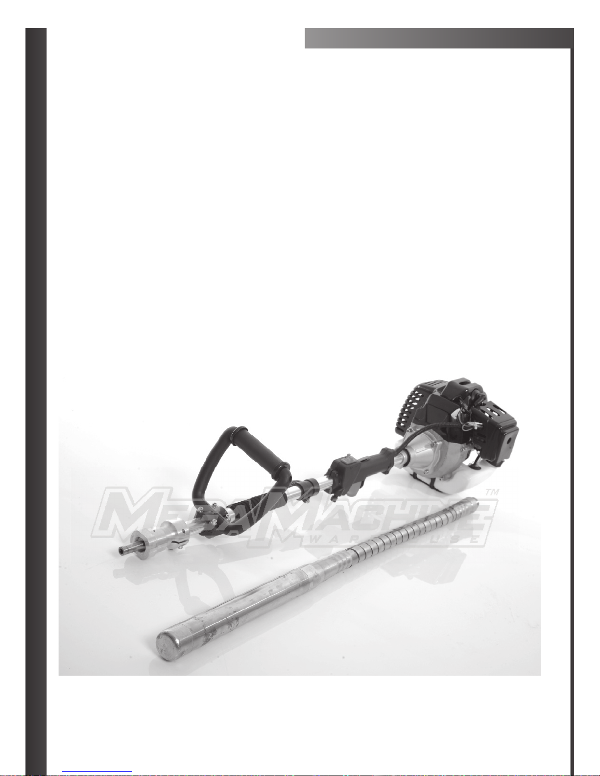
STEELTEC 52CC
CONCRETE VIBRATOR
CONTENTS OF BOOKLET
Warnings Check List/Hazards & Risks Page 3-4
What Is In Your Box/Benefits Of Vibraon Page 5
Installing Motor to Vibrang Head/Assembling Handle To ShaPage 6
Fuel Mixture Page 7
Starng Your Machine Page 8
Adjusng Idle Screw On Your Machine 9
Maintenance Page 10

3
BEFORE USING THIS UNIT:
Please Read the Operator’s manual carefully.
Start the unit and check the carbureor adjustment (please check
Page 9 for this step if needed)
Always wear eye, head and ear protectors when
using this unit.
Keep all children, bystanders and helpers 15m (50) away from
unit. If anyone approaches you, stop the engine and cung
aachment immediately.
Gloves, safety goggles and ear muffs and slip and sturdy footwear
should be worn at all mes when operang tools or machinery.
MAINTAIN THIS MULTITOOL ACCORDING TO THE OWNER’S
HAZARDS AND RISKS
1. Never allow any person to operate equipment without adequate instrucon.
2. Serious injury may result from improper or careless use of this machine.
ALWAYS MAINTAIN THIS CONCRETE VIBRATOR ACCORDING TO THE
OWNER’S MANUAL AND FOLLOW THE RECOMMENDED SCHEDULED
MAINTENANCE.
ALWAYS USE GENUINE PARTS AND ACCESSORIES WHEN REPAIRING
OR MAINTAINING THIS MACHINE. DO NOT MAKE UNAUTHORIZED
MODIFICATIONS OR SUBSTITUTIONS TO THE MOTOR. NEVER ALLOW
THE ENGINE TO RUN AT HIGH RPM WITHOUT A LOAD, DOING SO
COULD DAMAGE THE ENGINE.
WHEN TRANSPORTING THE CONCRETE VIBRATOR IN A VEHICLE, TIE
IT DOWN SECURELY TO PREVENT DAMAGE AND FUEL SPILLAGE.
ALWAYS CLEAR YOUR WORK AREA OF TRASH OR HIDDEN DEBRIS TO
HELP ENSURE GOOD FOOTING.
4
MECHANICAL HAZARDS
1. Do not operate the machine unless all protecve guards
are in place.
2. Keep hands and feet clear of rotang and moving parts as
they will cause injury if contacted.
3. Do not leave the equipment in operaon while it is
unaended.
4. Exercise CARE when handling vibrators. Expose to vibraon
or repetave work acons may be harmful to hands and
arms.
5. DO NOT hold the vibrator shain your hands while it
is running. Hold the vibrator by the “D” handle and use the
supplied carry strap to help isolate your hands from the
vibraon.
6. Never stand on the vibrator head while it is operang.
7. DO NOT place your foot on the vibrator head while it is
running unless it is done momentarily and the vibrator
head is resng on a resillient support such as a car tyre.
8. Be careful not to come in contact with the muffler when
the engine is hot, since it can cause sever burns.
9. Ensure that repairs to machinery are carried out by
competent personnel.
FIRE & EXPLOSION HAZARDS
1. PETROL is extremely flammable and explosive under
certain condions.
2. Ensure that petrol is only stored in an approved storage
container.
3. DO NOT refuel the motor while it is in operaon or hot.
4. DO NOT overfill the fuel tank and avoid spilling petrol when
refueling. Spilled petrol of petrol vapour may ignite. If
spillage occurs, ensure that the area is dry before starng
the motor.
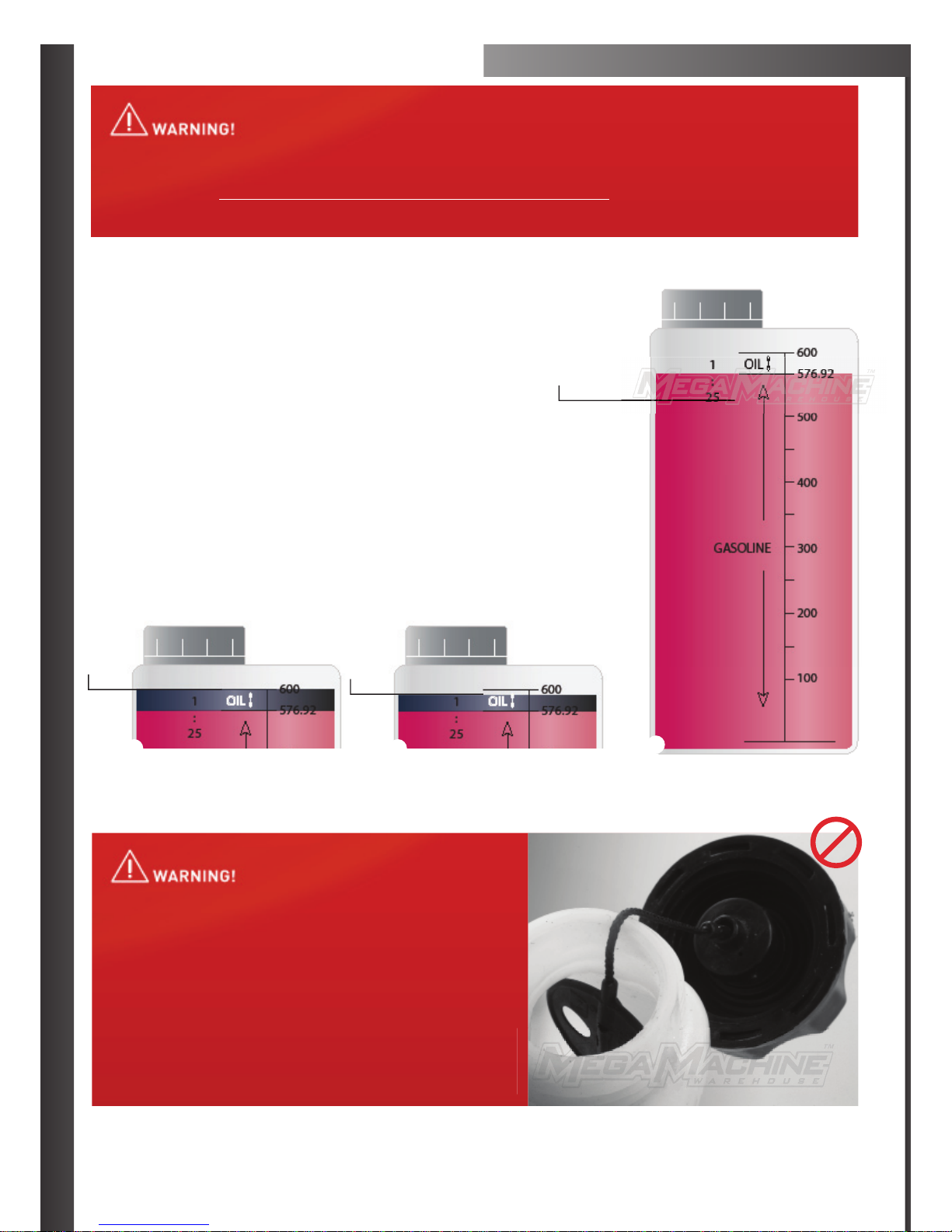
5. Most vibraons can cause an improperly ghtened fuel
capp to loosen or come offand spill quanes of fuel. In
order to reduce risk of fuel spillage and fire, ghten fuel
cap by hand with as much force as possible.
6. To reduce the risk of serious injury from burns, never
aempt to refuel the unit unless it has been stopped and
completely removed from the operator.

5
STANDARD COMPONENTS
A. Bolts for Handle
B. Handle
C. Boom Bracket
D. Vibrator Aachment
WHAT IS IN YOUR BOX
B
C
A
BENEFITS OF VIBRATION
The following is a list of benefits resulng from vibrang freshly
poured concrete.
1. Increases concrete strength by removing air voids.
2. Improves appearance by removing air voids.
3. Increases bond between concrete and reinforcing bars.
4. Fluidizes concrete allowing a sffer mix with a lower water to
cement rao to be placed. (This increases concrete strength)
5. Reduces cold joints and honey combing.
D

6
ASSEMBLING HANDLE TO SHAFT
STEP 1
Have all parts ready in order to
assemble handle.
STEP 2
Place lower bracket around sha.
STEP 3
Place top bracket around handle and place
bolts in to secure handle to the sha.
INSTALLING MOTOR TO VIBRATING HEAD
STEP 1
Place vibrang head up to motor.
STEP 2
Aach (turning an-clockwise) onto motor
to assemble.
PLEASE LUBRICATE INTERNAL ENGINE SHAFT CONNECTION &
THE CONNECTING FLEXIBLE SHAFT FOR ATTACHMENT AFTER SIX
HOURS OF USE. TO AVOID SHAFT DAMAGE OR BREAKAGE.
THE CONNECTING INTERNAL FLEXIBLE SHAFT SHOULD
ALWAYS LOOK LUBRICATED.
7
HOW TO MIX YOUR FUEL
Common mixtures are 25:1/30:1. If you find your machine is too
smoky please use the higher rao which is 30:1 as seen in diagram C.
WHAT IS 25:1/30:1?
The first part of the formula refers to how many parts of fuel as seen
in diagram A. The second part of the formula refers to how many
parts of oil (diagram B or C). For example, 25 parts of unleaded fuel or
low octane to 1 part of two stroke oil or 30 parts of unleaded or low
octane fuel to 1 part of two stroke oil.
REMEMBER TO MIX WELL (SHAKE BOTTLE)
ONLY USE THIS RECOMMENDED 2 STROKE FUEL MIX WITH A GOOD QUALITY 2 STROKE OIL FROM YOUR LOCAL SUPPLIER, USING A MIX
RATIO OF 25:1/30:1 IN THE MACHINE. UNLEADED OR LOW OCTANE FUEL ANY OTHER FUEL MUST BE USED IN A TWO STROKE MIX. MIX WELL
AS RECOMMENDED. INCORRECT MIX COULD DAMAGE YOUR ENGINE VOIDING YOUR WARRANTY, USE THIS FUEL MIX EVERY TIME YOUR
MACHINE IS IN OPERATION FOR THE BEST DINGO TOOLS PERFORMANCE YOU CAN EXPECT OUT OF YOUR DINGO TOOLS MACHINE.
FULL
30:1
C
25:1
BA
AT ALL TIMES PLEASE KEEP THE FUEL TANK FULL WHEN IN OPERATION,
“AVOID HAVING THE YOUR ENGINE FINISHING OPERATION FROM FUEL
STARVATION. FUEL TANKS BEING KEPT FULL AT ALL TIMES WILL IMPROVE
YOUR MACHINE PERFORMANCE.
FUEL RUNNING OUT WHILE IN OPERATION MAY DAMAGE YOUR ENGINE,
PLEASE BE SURE TO REFILL THE TANK, KEEPING THE FUEL WELL FILLED
DURING OPERATION IN ASSISTING AND AVOIDING BREAK DOWNS OR
OPERATION INTERRUPTIONS. FUEL TANKS BEING EMPTIED DURING
OPERATION, MAY RISK DEBRIS ALL FOREIGN OBJECTS ENTERING INTO
THE FUEL INTAKE CONFIGURATION SYSTEM CAUSING BLOCKAGES, OVER
HEATING AND EVEN PISTON FAILURE. TO AVOID THESE CIRCUMSTANCES
PLEASE KEEP YOUR FUEL TANK WELL FILLED AT ALL TIMES, AVOIDING
ENGINE BREAKS INCURRED, FROM THE RESULT OF FUEL STARVATION.

8
STEPS FOR STARTING YOUR MACHINE
STEP 1
Mix the 2 stroke fuel to the correct
rao (25:1)-(30:1) and fill the tank.
!SEE BELOW FOR FUEL INFORMATION
STEP 4
Slide the take on switch to the
down posion.
STEP 7
Pull the recoil 2–4 mes. By the fourth
pull, it should sound like the engine is
going to start. Move to Step 8.
STEP 2
Press the fuel bubble 5–7 mes (no
more than 7). Fuel should now fill the tube
next to pump.
STEP 5
Squeeze the top and boom levers
in and hold in firmly (as pictured in 5.2).
STEP 8
Slide the choke down to the boom
posion for the final starng and running
operaon of the machine.
STEP 3
Slide the choke to the up posion.
STEP 6
While holding top lever and boom
lever squeezed in, slide down or push in
the locking switch.
STEP 9
Pull the recoil once again, or unl
the engine starts.
CHOKE SETTINGS
OFF POSITION: IS FOR INITIAL STARTING
ON POSITION: IS FOR THE RUNNING OPERATION OF THE MACHINE

9
ADJUSTING IDLE SCREW
ON YOUR MACHINE
If your Idling of your brushcuer needs adjusng e.g it is idling too fast or slow or is cung out please follow the steps below on how to adjust
this on your machine.
When looking down in a birds eye view at the carby or Choke area, at the the top of the Carby where the throle control cable aaches to the
side of the mechanism, you will see a silver screw on the right hand side at the top.
Where the Sliver Screw enters in and the p of the Silver Screw comes out the outer side, you should be able to view when looking at least 3 –
4mm of screw p, turning this screw to the lewill speed up the idle, while turning the silver screw to the right will slow the idle down.
We suggest that you adjust the screw so you may be able to view 3 or 4mm of screw p, if you see more screw p, please back adjust the
screw to this suggested seng and if you are viewing less of the screw p, please adjust the screw so you are able to view more of the p at
least 3 or 4mm of screw p and no more or less.
FUEL MIXTURE SCREW ADJUSTMENT
If your machine is not revving or not running correctly please
adjust the Fuel Mixture Screw with the steps
to the right.
When facing the Carby side of the machine and looking at the
carby on the right hand side of the Carby down near the top of
the fuel tank and infront of the black fuel line in take tube, you
will see a brass screw, this is the fuel mix screw, this adjusts how
much fuel may enter the machine.
To set this screw in the correct posion we need to start the screw at zero first, please turn the brass screw all the way to the right or clock wise
unl it will not turn any further, please try not to over turn it when screwing it all the way in, as when you have reached the end of it’s thread
and if you keep turning it with force, you may snap the screw off.
When you have turned the screw all the way in to the right or clock wise so it can not turn any further this is what we call or state as being
at zero. Now please turn the screw 1 and 1 quarter turns to the leor anclock wise to set it in the correct posion for the fuel intake and
smooth operaon.
*** NOTE ***
If 1 and 1 quarter turns isnt enough as the adjustment has not being successful please start the brass screw back at zero and try
a 1 and half full turns anti clock wise or to the left to set the carby with a little bit more fuel into the machine.

10
MAINTENANCE
Keep the unit clean and free of concrete residue.
Check the oil level in the engine crankcase daily, it should reach the
edge of the oil filler neck. The engine oil capacity is only 100 ml and
running the engine with a low oil level will cause serious engine
damage.
Vibrators must be handled with care, and be properly maintained in
order to avoid unnecessary breakdowns. Check regularly for signs of
wear and recfy any faults immediately.
The exterior of the flexshaand the vibrator head are subject to
abrasion and wear. If the vibrator is operated unchecked, concrete will
eventually enter the vibrator head or the flexsha. Naturally, the cost
of repairing a vibrator which has been allowed to deteriorate in this
way will be greater.
Regular inspecon of the vibrator and the flexible shawill avoid
these problems.
Check the flexible shafor kinks and external damage by laying it
out straight on a workbench or the floor. Althought it sll operates, a
badly kinked flexible shamay result in a broken inner core.
Check the outer casing rubber cover for damage where it enters the
ferrule at the vibrator head. Damage is caused by operators using a
crane to retrieve a vibrator trapped in concrete reinforcing bars.
PLEASE LUBRICATE INTERNAL ENGINE SHAFT CONNECTION &
THE CONNECTING FLEXIBLE SHAFT FOR ATTACHMENT AFTER SIX
HOURS OF USE. TO AVOID SHAFT DAMAGE OR BREAKAGE.
THE CONNECTING INTERNAL FLEXIBLE SHAFT SHOULD
ALWAYS LOOK LUBRICATED.
Other manuals for 52CC
1
Table of contents
Other STEELTEC Power Tools manuals


