Steelwrist Tiltrotator Front pin lock X04 User manual

User Manual
Tiltrotator Front pin lock™X04, X06, X07, X12, X18, X20, X26
XControl G2
DocNo: 700347ENA


User Manual
Tiltrotator Front pin lock™X04, X06, X07, X12, X18, X20, X26
XControl G2
DocNo: 700347ENA

User Manual
Tiltrotator Front pin lock™X04, X06, X07, X12, X18, X20, X26
Published by:
Steelwrist AB
Bäckvägen 18
192 54 Sollentuna
Sweden
+46-626 07 00
www.steelwrist.com
Translation of Original User Manual
Copyright ©2013, Steelwrist AB. No part of this document can be reproduced.
4| User Manual tiltrotator with Front pin lock™| Introduction

Contents
1. Introduction.....................................................................................................7
1.1. EC Declaration of Conformity.................................................................................................................8
1.2. Thank you for choosing a tiltrotator from Steelwrist................................................................................9
1.3. Steelwrist Design Philosophy...............................................................................................................10
2. Safety.............................................................................................................11
2.1. Safety Levels........................................................................................................................................12
2.2. Safety regulations.................................................................................................................................12
2.3. Machine plate and warning labels........................................................................................................13
2.4. Type certificate for lifting hook..............................................................................................................15
3. Product Description......................................................................................17
3.1. Function description..............................................................................................................................18
3.2. Tilt rotator main parts............................................................................................................................19
3.3. Hydraulic system..................................................................................................................................21
3.4. Electrical control system.......................................................................................................................23
4. Technical data...............................................................................................27
4.1. Technical data.......................................................................................................................................28
4.2. Technical data - hydraulics...................................................................................................................28
4.3. Technical data - weights and dimensions.............................................................................................29
4.4. Technical data - gripper cassette..........................................................................................................29
4.5. Tightening torque..................................................................................................................................29
5. Operation.......................................................................................................31
5.1. Operating the lock function...................................................................................................................32
5.2. Operation of the tilt function..................................................................................................................32
5.3. Operating of the rotation function.........................................................................................................33
5.4. Operation of the extra function.............................................................................................................33
5.5. Operation of the gripper function..........................................................................................................33
5.6. Other functions.....................................................................................................................................34
5.7. Operation of the excavators quick coupler...........................................................................................34
5.8. Connecting work tools..........................................................................................................................34
5.9. Disconnecting work tools......................................................................................................................36
5.10. Using the lifting hook..........................................................................................................................37
6. User interface................................................................................................39
6.1. Understanding the user interface..........................................................................................................40
6.2. Operating mode....................................................................................................................................40
6.3. Menu:....................................................................................................................................................41
6.4. Speed....................................................................................................................................................42
6.5. Brightness.............................................................................................................................................42
User Manual tiltrotator with Front pin lock™| TOC | 5

6.6. Profile Management..............................................................................................................................42
6.7. Layout...................................................................................................................................................44
6.8. Clinometer............................................................................................................................................44
6.9. Troubleshooting....................................................................................................................................45
6.10. Troubleshooting - in / out signals........................................................................................................46
6.11. Language............................................................................................................................................46
7. Wheels and Track steering (Option)............................................................49
7.1. Introduction Wheels/Track steering......................................................................................................50
7.2. Function description Wheels/Track steering.........................................................................................50
7.3. User interface Wheels/Track steering...................................................................................................52
8. Environmental aspects.................................................................................55
8.1. Environmental information....................................................................................................................56
9. Maintenance..................................................................................................57
9.1. General Maintenance...........................................................................................................................58
9.2. Grease and hydraulic oil.......................................................................................................................58
9.3. Axial and radial play..............................................................................................................................58
9.4. Checkpoints..........................................................................................................................................59
9.5. Lubrication points..................................................................................................................................60
9.6. Full Service...........................................................................................................................................60
9.7. Check list - Delivery of the machine.....................................................................................................61
9.8. Check list - Weekly inspection and lubrication......................................................................................61
9.9. Check list - Daily inspection and lubrication.........................................................................................61
9.10. Feedback............................................................................................................................................62
6| User Manual tiltrotator with Front pin lock™| TOC


1.1. EC Declaration of Conformity
EC Declaration of Conformity according to Directive 2006/42/EC, Appendix IIA
Steelwrist AB, Bäckvägen 18, 192 54 Sollentuna, Sweden, hereby certify that the manufacturer:
Table 1: Tiltrotator
Type:
Serial number:
Weight:
Upper coupler:
Attachment coupler:
Gripper:
Oil type used when tested:
Type of lubrication in the gear box:
Schematics - Part number:
Delivery Date:
The above machine meets the requirements of the Directive 2006/42/EC and the following parts of harmonized
standards and technical specifications as stated below.
SS-EN474-1:2006+A1:2009, SS-EN474-5:2006+A1:2009, SS-EN12100:2010, ISO/DIS13031.2.
This declaration and Steelwrist guarantee is void if changes or other interventions are made without Steelwrist
approval.
The technical documentation for this product is held at the above address.
Questions are answered by the CTO or CEO.
Stefan Stockhaus, CEO, Steelwrist AB
8| User Manual tiltrotator with Front pin lock™| 1. Introduction

1.2. Thank you for choosing a tiltrotator from Steelwrist
We would first like to thank you for the confidence in choosing a tiltrotator from Steelwrist. At Steelwrist we work
hard to build tiltrotators that are well adapted to modern excavators. We will do everything we can for you to be
happy with your Steelwrist.
To obtain the best performance and reduce the risk of accidents, it is essential that the tiltrotator is installed,
maintained and operated properly. Carefully read the user manual and understand the content before starting to
use the product. To ensure a long product life span, reliability and cost effectiveness, it is important to regularly
inspect and maintain the product. This is part of the proper use of Steelwrist tiltrotators. We as a manufacturer can
not be held responsible for accidents or accept complaints if the cause is due to inadequate inspection and
maintenance or incorrect operation.
Steelwrist products are CE marked. This means that they are designed, manufactured and described in accordance
with current directives and requirements. However, it is important that all security requirements are considered in
the installation, maintenance and use. This is the case for safety regulations in this manual, the excavator's manual
and local safety rules relating to the area where the machine is used. If the tiltrotator rebuilt or complemented in a
way without Steelwrists written approval the CE marking and warranty ceases to apply immediately. Steelwrist
reserves the right to make technical changes without prior notice.
This manual is intended to provide the necessary information about the function, operation and maintenance of
your Steelwrist. (Installation instructions are in a separate document.) Ensure that the manual is always readily
available in the machine's cabin.
Yours sincerely,
Stefan Stockhaus
Steelwrist AB
User Manual tiltrotator with Front pin lock™| 1. Introduction | 9

1.3. Steelwrist Design Philosophy
Steelwrist's development work is aimed at giving you a tiltrotator that is optimized for your excavator. To enable
you to get the best digging geometry and best fuel efficiency, we have designed a tiltrotator that is robust, low
weight, has a low overall height and also has a high tilt angle. Over the excavator's lifetime, this optimization often
results in savings equivalent to a large part of the tiltrotator's total purchase cost compared to other alternatives
that may be heavier and have a higher building height.
You will recognize our efforts by:
• 45 degree tilt angle for high flexibility and fewer machine movements
• Steel casted gearbox and other casted components for best strength/weight relationship
• Truss structure construction in upper coupler and attachment coupler for strength and lower weight
• Low building height for maintaining the best digging geometry
• A control system that is easy to use and that ensures the lowest possible fuel consumption.
• Front pin lock™for increased safety when changing work tool.
10 | User Manual tiltrotator with Front pin lock™| 1. Introduction


2.1. Safety Levels
Most accidents occur as a result of carelessness or negligence to follow given safety instructions. For us at Steelwrist
safety is very important and we will do our best to avoid risks with preventive measures. However no safety instruction
or protection measure, no matter how good they are made, is better than a prudent machine operator.
In order to classify risks we use the following safety standards and recommendations in this manual:
Danger:
• Danger (Danger) indicates that an accident will occur if the regulation is not followed. The accident will
result in serious injury or death.
• Read carefully the user's manual and understand the contents before the product is first installed and
used. Avoid dangerous work situations. For questions, contact your dealer or Steelwrist.
Warning:
• "Warning" indicates that an accident could occur if the regulations are not followed. The accident could
result in serious injury or death.
• Read carefully the user's manual and understand the contents before the product is first installed and
used. Avoid dangerous work situations. For questions, contact your dealer or Steelwrist.
Caution:
• "Caution" indicates that an accident may occur if the regulations are not followed. The accident may
result in serious injury or death.
• Read carefully the user's manual and understand the contents before the product is first installed and
used. Avoid dangerous work situations. For questions, contact your dealer or Steelwrist.
Note:
• "Note" could be something that we wish to draw your attention to that can increase or reduce the
performance of the product or of your excavator.
• Carefully read the user manual for your excavator together with this manual to ensure best possible
function and performance.
2.2. Safety regulations
Steelwrist tiltrotators can be used with a variety of tools that, correctly used, increase the excavator's productivity
significantly. Work tools, however, have to be be of the type normally used when working with excavators. No other
use may occur without Steelwrist written approval. The tiltrotator is also designed to manage a certain torque and
excavators of a certain machine weight. The tiltrotator should not be installed on an excavator above the specified
weight. However, it is possible to mount a tiltrotator on a machine with lower performance than the intended machine
weight, provided that tiltrotators own weight is taken into account. Ensure that your tiltrotator match the excavator's
performance. See: Technical data
Warning: Never use tiltrotator or attachment to lift a person.
Warning: Always follow safety instructions for the machine, tiltrotator and work tools.
Warning: Do not stay near the work tools when the machine is in use and always stay clear from lifted
work tools.
Warning: When the tool is being connected or disconnected, the safety distance is three meters from the
work tool. (For some types of hydraulically powered tools the safe distance can be even higher, consult
the user manual for the work tool.)
Warning: Only authorized and trained personnel may use tiltrotator. It is important that the driver take the
time to learn how to manage to tiltrotator safely before using the machine.
12 | User Manual tiltrotator with Front pin lock™| 2. Safety

Warning: Always turn off the machine for maintenance and repair work.
Caution: Remember to relieve pressure in hydraulic system before work is started. Be careful when
searching for leaks as hot hydraulic fluid can cause skin burns, and hydraulic fluid under pressure can
penetrate skin.
Note: Excavator geometry changes with the quick coupler/tiltrotator mounted. Compared with an excavator
without a quick coupler the reach is extended range while the weight increases. Choose the size of buckets
and other work tools with this in mind.
Note: Works with breakers can cause vibration damage to tiltrotator with accident and personal injury.
Do not use larger breakers than specified in the machine manual. Avoid where possible, work using
hydraulic breakers.
Note: Follow the recommendations in Maintenance to reduce the risk of injury and ensure the longevity
of the tiltrotator.
Note: The indication on the quick coupler can differ from other couplers and tiltrotators.
2.3. Machine plate and warning labels
Your tiltrotator is marked with a machine plate as follows:
The machine plate shows the tiltrotator model, serial number, maximum lift weight with gripper and lifting hook,
maximum hydraulic pressure, weight, year of manufacture, CE-marking and contact information for Steelwrist.
In addition to machine plate so there is also a warning label that must be visibly mounted in the cabin. The warning
labels pinpoints safety risks and is therefore of crucial importance. Exchange damaged labels when needed. Contact
your supplier or Steelwrist if the old labels have been damaged and you need new ones.
The text above in the local language:
User Manual tiltrotator with Front pin lock™| 2. Safety | 13

• Read the tiltrotator user manual!
• This machine is equipped with a Steelwrist tiltrotator
• Never go under a lifted attachment
• Attachments can be moved sideways, as well as tilt and rotate
• The danger area around tiltrotator is three meters. Be extra cautious when handling long objects.
• Always check that any attachment is properly locked after each change.
• Do not exceed the machines lifting capacity
• Never use the tiltrotator to lift persons
• Never leave the operators cabin with the tiltrotator lifted.
• For questions, contact your dealer or Steelwrist.
14 | User Manual tiltrotator with Front pin lock™| 2. Safety
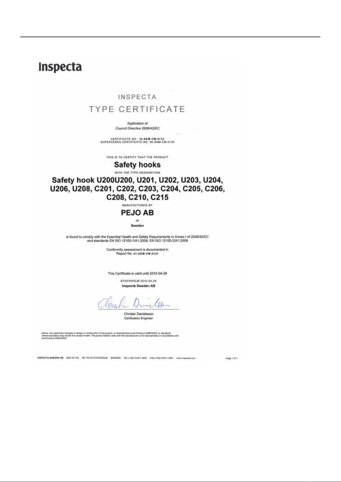
2.4. Type certificate for lifting hook
The following type certificate is valid for lifting hooks used on Steelwrist products.
User Manual tiltrotator with Front pin lock™| 2. Safety | 15


3.1. Function description
This function description gives an overall description of the Steelwrist tiltrotators structure and principle of its
operation.
The tiltrotator is an hydraulic work tool aimed to be mounted an excavator or backhoe loader. The tiltrotator is used
to position various work tools by combining a tilting and rotating movement.
Tilting movement:
Rotation movement:
The connection to the excavator can be either direct mounted or following a standard that fits the excavators quick
coupler. In general, the smaller the excavator the more frequent direct fit tiltrotators.
On the international market, there are several different quick coupler standards which can be divided into dedicated
mounting standards (quick coupler that fit on one bucket type that must comply with the standard), and universal
standards (quick coupler that fit with different types of buckets, mainly various original buckets from different
manufacturers of excavators ). Various attachment standards have different performance in terms of height, weight,
width and surface structures for assimilating digging forces. Very high, heavy or large attachments, such as, for
example Pin Grabbers (UK) and Verachtert (Holland), mean that these, from a performance perspective, do not
lend themselves in a favorable way to be combined with a quick coupler such as the mounting on top of the tiltrotator.
These tiltrotators should therefore be made direct fit.
The tiltrotator consists of a number of parts as follows:
18 | User Manual tiltrotator with Front pin lock™| 3. Product Description

1. Excavator dipper arm
2. Excavator quick coupler
3. Tiltrotator - upper coupler with tilt cylinders (may be one or two tilt cylinders, depending on the excavator's size)
4. Tiltrotator - gearbox with hydraulic manifold
5. Tiltrotator - attachment coupler with front pin lock™
When tiltrotator is used together with a quick coupler: See the excavators and quick coupler user manuals.
The weight of the tilt rotator weight impacts the machine's lifting capacity. It is therefore important that the excavators
lifting capacity is matched against the weight of the tiltrotator. Possibly also bucket sizes and other tools may have
to be adapted to the new conditions.
The work tool width in combination with driving techniques are essential for the load, and therefore wear and tear.
Do not use a wider work tool than what is stated in Technical Data and never larger than what the machine supplier
recommends. To reduce the risk for excessive wear and tear, the driver should always endeavor to balance the
digging force along the work cutting edge.
Also consider the following:
• The tiltrotator is not intended for continuous rotation for a long time (grilling type of work). Reason being risk of
overheating and pinching.
• Do not expose the tiltrotator to abnormal forces, for example by hitting buckets to hard surfaces.
• Avoid exposing the tilt cylinders for peak forces at the end position.
• Work with hydraulic breakers or similar work tools can often expose the tiltrotator to exessive forces thus shorten
the life of the equipment. Therefore, such work is should where possible be performed without tiltrotator.
3.2. Tilt rotator main parts
Tiltrotator is basically made up of six subsystems: an upper coupler (direct mounted or following a standard) with
tilt cylinders, a gearbox / rotor unit, an attachment coupler, a gripper cassette which is optional, and a hydraulic
systems and associated electrical control systems. Hydraulic systems and control systems are described separately
below.
Upper coupler:
User Manual tiltrotator with Front pin lock™| 3. Product Description | 19
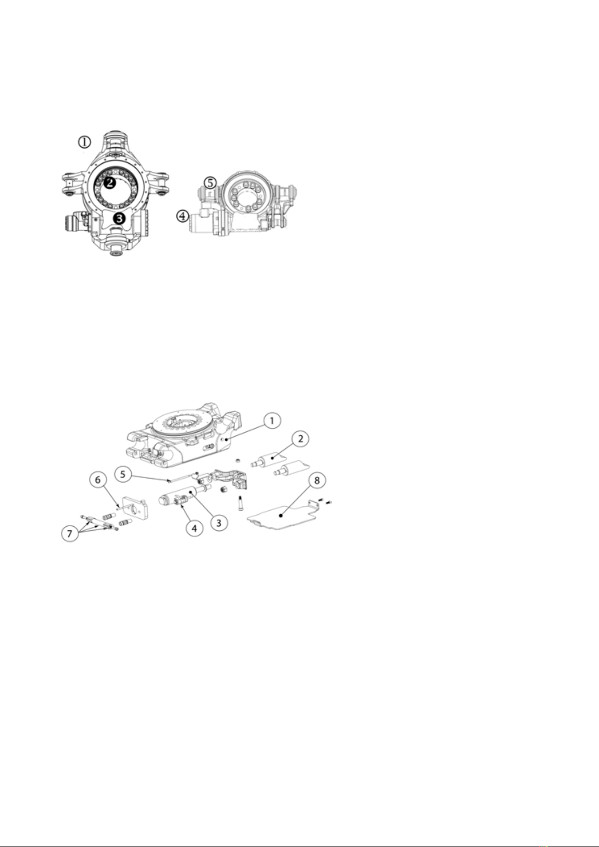
1. Upper coupler:
2. Tilt cylinder
Upper coupler to excavator and double-acting tilt cylinders. In the upper coupler the gearbox is mounted via two
joints (so-called tilt shafts). The tilt shafts makes the tiltrotator tiltable. The tilt movement is achieved with the tilt
cylinders.
Gearbox:
1. Gearbox
2. Gear wheel
3. Worm
4. Hydraulic motor
5. Tilt shafts
The link between the upper coupler and the attachment coupler, consists of a worm gear with a worm and a gear
wheel. The gear wheel is bolted to the attachment coupler with high tensile strength screws. The rotation is achieved
with an hydraulic motor driving the worm, which in turn rotates the gear wheel and thus the attachment coupler.
Attachment coupler:
1. attachment coupler
2. Locking pins
3. Locking cylinder
4. Check valve
5. Indicator bar red (for open quick coupler)
6. Indicator bar green (for locked/secured quick coupler)
7. Front pin lock™
The attachment coupler is used to lock the work tool by a hydraulic cylinder pushing a locking pin under the rear
pin of the work tool. This is done with a hydraulic cylinder ("the locking cylinder") and locking pins. For a secure
locking function, it is essential that the locking pins enclose the pins of the work tool. When the locking cylinder is
in its retracted position the lock is open and it is possible to connect or disconnect a work tool.
Front pin lock™is a safety function that locks the front bracket pin of the work tool in the attachment coupler when
the locking cylinder and locking pins are in the extended position. It prevents the work tool coming loose from the
coupler if the locking pins are accidently retracted above the rear bracket pin. This reduces the risk of dropping a
tool and causing an accident when changing tools. Front pin lock™is based on two locking wings engaging and
preventing the bracket pin from coming out of the front grip when the lock cylinder is in the extended/locked position.
Tools can be attached when the attachment coupler is both locked and open.
When the quick coupler is locked, this is indicated by a green indicator bar (right) protruding at the front edge by
the work tool shaft. When the quick coupler is open, a red indicator bar (left) is visible, see image below.
20 | User Manual tiltrotator with Front pin lock™| 3. Product Description
This manual suits for next models
7
Table of contents
Popular Industrial Equipment manuals by other brands


PushCorp
PushCorp AFD1240 manual

ABB
ABB HT609436 operating manual

ENFORCER
ENFORCER SM-4601-LQ manual

Halma
Halma Crowcon Xgard S011843 Installation, operating and maintenance instructions

Shel lab
Shel lab SCO58 Installation and operation manual

KTR-Group
KTR-Group ROTEX 001 Operating & assembly instructions