PUSHCORP, INC.
AFD1240 Manual
The bolt pattern on the Carriage has been designed to facilitate process equipment
installation. The Carriage has (34) thirty-four M8x1.2 mounting holes with a depth
of 0.47 inch (12 mm) to provide secure attachment points. The mounting holes are
spaced 8 inches (127 mm) across and on 2 inch (2 .4 mm) centers along the length
of the Carriage. (See Figure 1) The Carriage also has (4) four mm dowel pin holes
to facilitate alignment. (See Figure 1 for location) These dowel pin holes are
oversized to allow the pins to be glued into place using Loctite 609, or equivalent.
ARNING: DO NOT press pins into the AFD Carriage as this will likely damage
the bearing Linear Rails.
CAUTION: The Fastener Tightening Torque Specs chart in Section 6.0 should
be used to determine proper fastener length and torque for fasteners into the
Carriage. This is to prevent pull-out of the Carriage helicoil inserts.
4.2 Mounting the 1240 Series
The basic configuration of the 1240 Series force device allows attachment to a
stationary fixture or a robotic manipulator mounting flange. Specifying an AFD1240
-1 or -2 determines which Mounting Bracket is supplied. Adapter plates or "quick-
change" attachments can be used as well for mounting. The 1240 Series has (2)
two 4mm dowel pins pressed into the base for location and alignment of the cover
and Mounting Brackets.
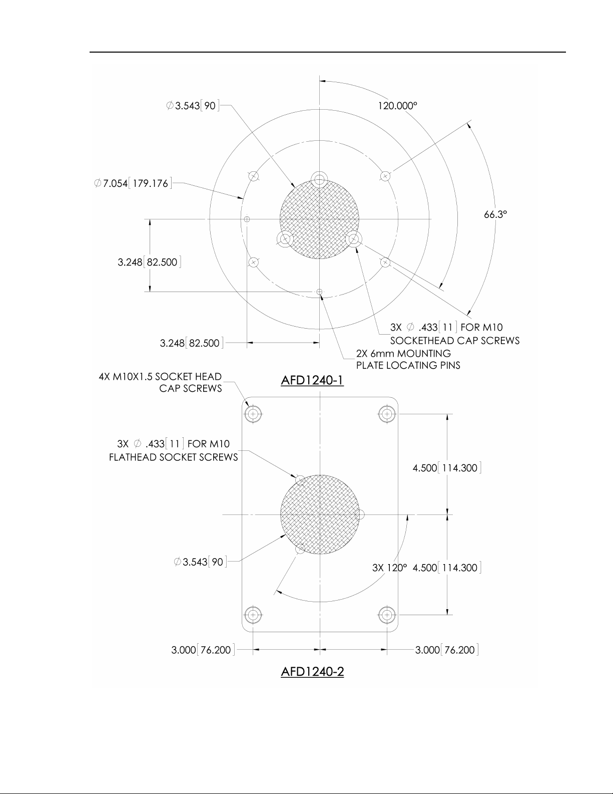
4.2.1 Mounting the AFD1240-1 Vertical and AFD1240-2 Horizontal
The AFD1240-1 and AFD1240-2 are supplied with a standard Mounting Bracket with
a 90 mm three hole mounting pattern, See Figure 2. All three holes should be
utilized to secure the Mounting Bracket to the robot mounting flange. If the Mounting
Bracket is supplied blank or additional holes are required, it must first be removed
from the device before drilling. Four cap screws are used to attach the Mounting
Bracket to the 1240 Series. Once the Mounting Bracket is removed, mounting holes
may be placed anywhere within the crosshatched area shown in Figure 2.
PushCorp, Inc. will supply engineering support to determine the mounting hole
locations at no cost.
After drilling the required hole pattern, remove any burrs and clean any machining
residue from the Mounting Bracket. The Mounting Bracket can then be reattached.