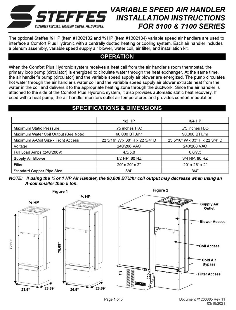
Steffes 5100 Series User manual

VARIABLE SPEED AIR HANDLER
INSTALATION INSTURCTIONS
FOR 5100 & 7100 SERIES
Page 1 of 5 Document #1200365 Rev 10
09/04/2020
½ HP
23.5”
23.69”
72.69”
26.5”
23.69”
75.69”
¾ HP
Figure 1
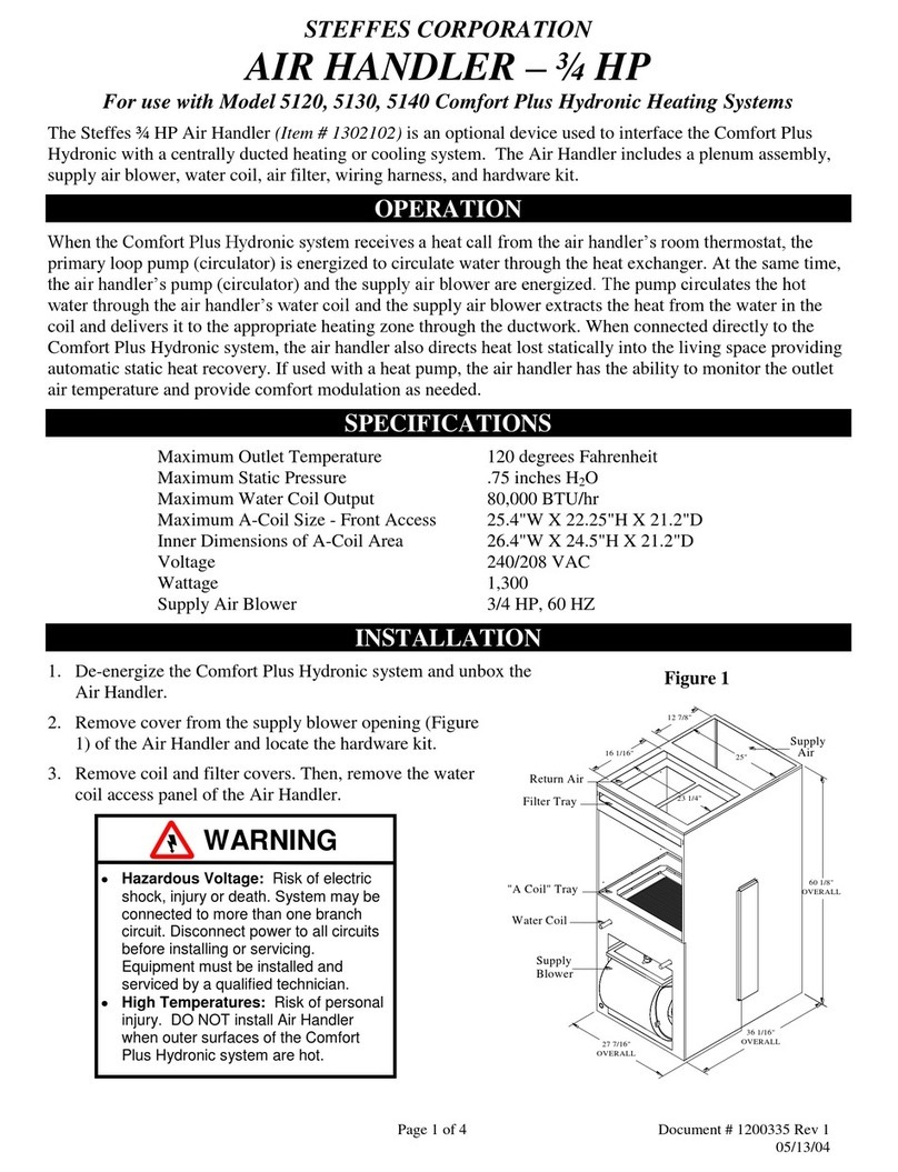
The optional Steffes ½ HP (Item #1302132 and ¾ HP (Item #1302134) variable speed air handlers are used to
interface a Comfort Plus Hydronic with a centrally ducted heating or cooling system. Each air handler includes
a plenum assembly, variable speed supply air blower, water coil. air filter, and installation kit.
OPERATION
When the Comfort Plus Hydronic system receives a heat call from the air handler’s room thermostat, the
primary loop pump (circulator) is energized to circulate water through the heat exchanger. At the same time,
the air handler’s pump (circulator) and the variable speed supply air blower are energized. The pump circulates
hot water through the air handler’s water coil and the variable speed supply air blower extracts heat from the
water in the coil and delivers it to the appropriate heating zone through the ductwork. Since the air handler is
attached to the side of the Comfort Plus Hydronic system, it also provides automatic static heat recovery. If
used with a heat pump, the air handler monitors outlet air temperatures and provides comfort modulation.
SPECIFICATIONS & DIMENSIONS
NOTE: If using the ¾ or 1 HP Air Handler, the 90,000 BTU/hr coil output may decrease when using an
A-coil smaller than 5 ton.
1/2 HP
3/4 HP
Maximum Static Pressure
.75 inches H2O
.75 inches H2O
Maximum Water Coil Output (See Note)
60,000 BTU/hr
90,000 BTU/hr
Maximum A-Coil Size - Front Access
22 5/16” W x 30” H x 22 3/4” D
25 5/16” W x 33” H x 22 3/4” D
Voltage
240/208 VAC
240/208 VAC
Full Load Amps (240/208V)
4.3/5.0
6.8/7.3
Supply Air Blower
1/2 HP, 60 HZ
3/4 HP, 60 HZ
Filter
20” x 20” x 2”
20” x 25” x 2”
Standard Copper Pipe Size
3/4”
3/4”
Filter Access
Coil Access
Blower Access
Supply Air
Outlet
Figure 2

Variable Speed Air Handler Instructions(continued). . .
Page 2 of 5 Document #1200365 Rev 10
09/04/2020
INSTALLATION
THIS PROCEDURE MUST BE PERFORMED BY A QUALIFIED TECHNICIAN
NOTE: Per UL requirements, the air handler must be mounted to the right side of the Comfort Plus
Hydronic system.
1. De-energize the Comfort Plus Hydronic system and unbox the air handler.
2. Remove the blower and coil access covers from the air handler (Figure 2).
3. Remove the air handler base from inside the air handler.
4. Remove the filter from the base and locate the hardware kits.
5. Mount the air handler base to the base of the furnace using the index holes
as shown in Figures 3 and 4. Figure 4 is, as viewed, looking up and into the
base of the air handler. Scres for attaching the base are included in the
hardware kit.
6. Install support brackets, as shown in Figure 5.
7. Cut a return opening into the base of the air handler.
The return should be sized for the installation and can
be cut into any one of the three available sides or the
bottom of the air handler base below the filter assembly.
8. Set the air handler onto the air handler base. Attach the
two together using eight of the screws provided in the
hardware kit. There are two screws per flange.
9. Attach the side of the air handler to the top of the
furnace using the 1” x 22” L-bracket shopped in the
supply air outlet (Figure 2) and six of the self drilling
screws provided.
10. Loosen connector nut on the flexible conduit
approximately 1/8”. Slide connector into slot as shown
in Figure 6. The washer and nut must be on the inside
of the panel. Snap strain relief bushin into place.
11. Revome the elctrical panel cover of the Comfort Plus
Hydronic system and locate the air handler wires in the
lower right side of the electrical compartment. Remove
and discard the resistor connecting the two brown wires.
12. Attach the 1/2" flexible conduit connector to the air handler’s umbilical cord and furnace See Figure 8.
13. Connect the wires from the Air Handler to the corrosponding colored wires from the Comfort Plus Hydronic
system (Figure 9). Connect the green ground wire to one fo the steet metal screws that secure the circuit
breaker standoff.
•Hazardous Voltage: Risk
of electric shock. Can
cause injury or death.
System may be connected
to more than one branch
circuit. Disconnect power
to all circuits before
installing or servicing.
Equipment must be
installed and serviced by a
qualified technician.
•High Temperatures: Risk
of personal injury. DO
NOT install Air Handler
when outer surfaces of the
Comfort Plus Hydronic
system are hot.
WARNING
Figure 4
Figure 3
Support
Brackets
Figure 5
Figure 6
Figure 8
Figure 7
Figure 9

Variable Speed Air Handler Instructions(continued). . .
Page 3 of 5 Document #1200365 Rev 10
09/04/2020
NOTE: Generally, 400 CFM of air flow is
recommended per ton of cooling.
Therefore, a 3-ton heat pump or air
conditioner requires 1200 CFM.
14. Connect the 7-pin harness to the port
labeled “Blower” on the LV circuit board
(Figure 10).
15. If an outdoor sensor is used, connect the
sensor wires to the “Outdoor” terminals
(Figure 10).
16. If utilizing low voltage peak control, connect
the peak control device to Peak Input
terminals “RP” and “P” (Figure 10).
17. Using the chart below, select the proper
“Blower Speed” at the LV circuit board. See
Figure 10.
18. The “W-E” jumper MUST be in the “OFF” position.
NOTE: If the W-E jumper is “ON” when installed in a hydronic heating system, the air handler will
run with an “H” call from the thermostat. See Figures 11, 12, and 13.
19. If installing system with a two-stage heat pump, the Y1-Y2 jumper must be placed in the “OFF” position.
NOTE: If using a two-stage heat pump, a “Y1” signal will yield ½ of the maximum CFM selected. A
“Y2” signal will yield maximum CFM selected. See Figures 11, 12, and 13.
20. Connect field wiring from the room thermostat to the LV circuit board using the appropriate wiring diagram
from the “Room Thermostat Interface” section of these instructions.
ROOM THERMOSTAT INTERFACE
The variable speed ECM motor adjusts motor speed to achieve the appropriate CFM for the thermostat input
received. The maximum CFM required is selected at the ECM motor interface board during installation.
Jumper ½ HP Variable
Speed CFM
¾ HP Variable
Speed CFM
A
1000
1200
B
1200
1400
C
1400
1600
D
1600
2000
Figure 10
Outdoor Sensor Connections
Low Voltage Peak
Control Connections
7-pin Harness
Blower Speed
Selection
W/
NO
NC
COM
Outdoor
Outdoor
CR
H/E
The Y1/Y2 Jumper must be installed
RLY1 D6
To Control Board
Fid 2 D4
Blower
To Control Board
O
D3
R2
R1
D7D5
P11
W E
Y1 Y2
Water
J4
D1
P5
J1
J2
J3
P10
P6
D2
D
A
B
C
C3
J5
J6
Blower
Speed P4 P3
AUX Y2 G
Y1 O22 Y2Y1
R
Air
LV Circuit Board
Comfort Plus
P7
P8
P2 P1
C
P9
RP
2APP
Aux.
Relay
Peak
Inputs
G
TH5110D R
C
W
Y
Honeywell Rc
(If being used in the application)
Air Conditioner Connections
C
Y
The W/E Jumper must be removed
Hydronic Heat Thermostat, Zone
Valve, End Switch, or Pump Control
A
B
C
D
W / E
Y1 / Y2
J1
J2
J3
J4
J5
J6
Blower
Speed
* If multiple inputs are active, system will
display highest Heat Call values. "COOL"
overrides all inputs and stops all heating
operations.
** Ther
mostat must be programmed to energize
reversing valve for cooling. If outdoor unit
used requires the reversing valve be energized
for heating.
Figure 11
Stand Alone Furnace Application Connections Shown for
Single Stage Heating / Single Stage Cooling (Uncontrolled
Air Conditioning

Variable Speed Air Handler Instructions(continued). . .
Page 4 of 5 Document #1200365 Rev 10
09/04/2020
Hydronic Heat Thermostat, Zone
Valve, End Switch, or Pump Control
Honeywell TH5220D
LE Aux G O
/
B C Y R R
c
To Heat Pump
Y - Compressor
C - Low Voltage Common
R - Low Voltage Hot
O - Reversing Valve
Outdoor Sensor
The Y1/Y2 Jumper must be installed
The W/E Jumper must be removed
W/
AUX Y1 Y2 G O H/E R C Y12 Y22 O2
Peak
Inputs
RP P AP
Aux.
Relay
Blower
Speed
P11
D5 D7 D3
Blower
C3
Speed
P4
P3
P2
P1
P8 P9
R1
D2
R2 P10
D1
P5
P6
Comfort Plus
LV Circuit Board
P7
R C
RLY1 D6
Fid 2
D4
Blower
To Control Board
To Control Board
Figure 12
Single Stage Heat Pump Application
* If multiple inputs are active, system will display
highest Heat Call values. “Cool” overrides all inputs
and stops all heating operations.
** Thermostat mush be programmed to energize
reversing valve for cooling. If outdoor unit used
requires the reversing valve be energized for heating.
Hydronic Heat Thermostat, Zone
Valve, End Switch, or Pump Control
Honeywell TH5220D
L
Y2 Aux G O/B C Y R R
c
To Heat Pump
Y1 - Compressor
C - Low Voltage Common
R - Low Voltage Hot
Y2 - Compressor Stage 2 O
- Reversing Valve
Outdoor Sensor
The Y1/Y2 Jumper must be removed
The W/E Jumper must be removed
W/
AUX Y1 Y2 G O H/E R C Y12 Y22 O2
Peak
Inputs
RP P AP
Aux.
Relay
Blower
Speed
P11
D5 D7 D3
C3
Blo wer
Spee d
P4
P3
P2
P1
P8 P9
R C
R1
D2
R2 P10 D1 P5
P6
Comfort Plus
LV Circuit Board
P7
RLY1
D6
Fid 2
D4
Blower
To Control Board
To Control Board
Figure 13
Two Stage Heat Pump Application
* If multiple inputs are active, system will display
highest Heat Call values. “Cool” overrides all
inputs and stops all heating operations.
** Systems built before 1/1/2011 are configured
for 50% airflow in Stage 1. For more
information, refer to Instruction #1200601-
High Speed Stage 1 Relay Installation.
*** Thermostat mush be programmed to energize
reversing valve for cooling. If outdoor unit used
requires the reversing valve be energized for
heating.

Variable Speed Air Handler Instructions(continued). . .
Page 5 of 5 Document #1200365 Rev 10
09/04/2020
PLUMBING
Installation of the water coil plumbing should be
completed in a manner similar to the design shown
in Typical System Plumbing Diagram (Figure 14).
Standard copper pipe size 3/4".
Dedicated pump (circulator) to feed the water
coil and provide comfort modulation. Steffes
recommends a Taco 007 single speed 115
VAC pump (Order Item #1100002) or equal.
Maximum recommended water temperature
(as set in C011) is 180ºF/82ºC and the
minimum recommended water temperature (as
set in C012) is 150ºF/65ºC.
Pump serving the air handler is powered with
the black and white wires found in the junction
box on the lower left side of the Comfort Plus
Hydronic system. Refer to the Plumbing
Section of the Comfort Plus Hydronic Owner’s
and Installer’s Manual for more information.
Area in front of the air handler must remain
open for accessing the blower, filter, and coils.
NOTE: It is the responsibility of the installer to prevent involuntary flow of the water to the air
handler. Not doing so may cause limit tripping or decreased heat pump efficiency. Use of a
check valve, zone valve, etc. may help in this situation.
PLUMBING
The Air Handler filter should be replaced on a regular basis and general cleaning of the cabinet should be
conducted at the user’s discretion. No additional routine maintenance is required. Replacement filters can be
ordered from the factory (Order Item #1159017 for ½ HP and #1159063 for ¾ or 1 HP).
If utilizing a heat pump or air conditioner with the air handler, follow the manufacturer’s cleaning
recommendations for those devices.
WARNING
Risk of personal injury or property damage. Water
temperatures used for the Air Handler may not be
acceptable for other heating zones in the installation.
It is the responsibility of the installer to ensure that
proper tempering devices are in place.
FREEZE PROTECTION: Risk of frozen pipes. Can
cause property damage. Hydronic heating system
freeze-ups WILL cause extensive damage to the
entire heating system and/or property. Damage to the
air handler piping system can occur in low ambient
temperatures conditions or can be caused by a
system malfunction during air conditioning mode. It
is the responsibility of the installer to protect against
freezing of all plumbing and water coils.
PIPING SUPPORT: Risk of exchanger damage. Can
cause property damage or personal injury. DO NOT
use the exchanger as support for piping. Support
brackets should be in place to ensure proper
operation of the system and to keep pressure off the
inlet and outlet piping.
5100 Air
Handler
Secondary Loop
Low Temp Radiant Zones
Primary Loop
White
Orange
Mixing
Valve
-
+
-
From
Other
Zones
To
Other
Zones
White
Black
This Valve Must
Be Open During
Normal Operation
White
Red
Primary
Loop Pump
High Temp
Water
Comfort Plus
Hydronic
Exchanger
Figure 14
Other manuals for 5100 Series
1
This manual suits for next models
1
Table of contents
Other Steffes Air Handler manuals
Popular Air Handler manuals by other brands

York
York MCH CRAH quick start guide

Xvent
Xvent eLEMENTAIR B-MARK I Quick manual

VTS Medical Systems
VTS Medical Systems Ventus S Series Operation and maintenance manual

Trane
Trane BAYBRFBX100A Installer's guide

TGM
TGM CAH-F18CGR1-FQA-E3 Technical manual

McQuay
McQuay IM 777-3 Installation and maintenance manual

Salda
Salda RIS 1900 VEL EKO 3.0 QUICK LAUNCH GUIDE

McQuay
McQuay Skyline IM777 Installation and maintenance manual

Airflow
Airflow Adroit DV50 instruction manual

Kampmann
Kampmann KaCool HY 600x600 Installation, operation & maintenance manual

Samsung
Samsung AM0 SERIES Technical bulletin

Lennox
Lennox LGT Series Unit information