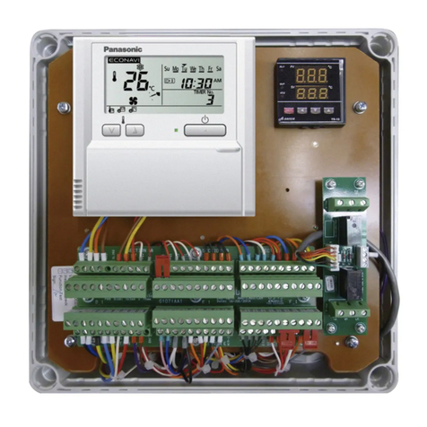
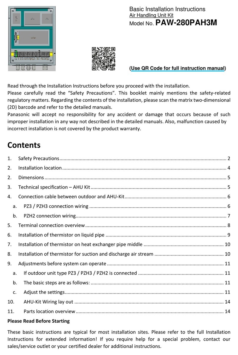
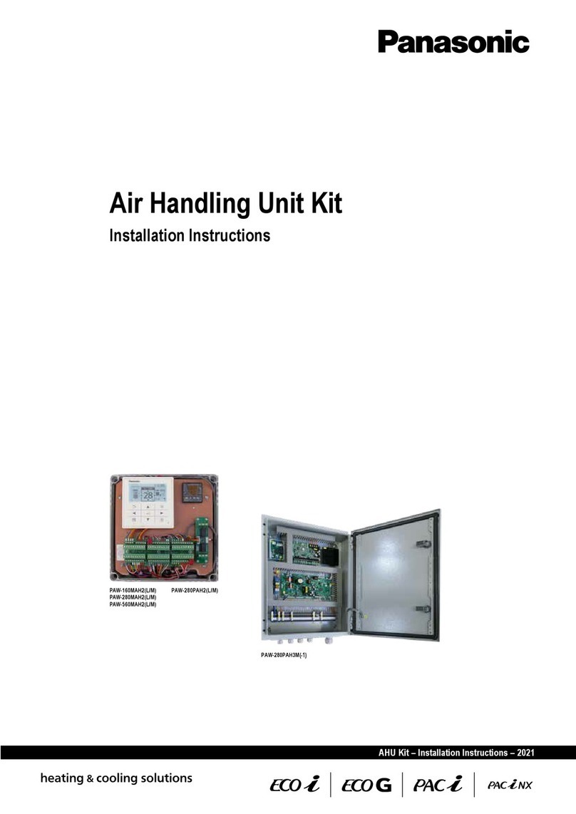
Panasonic PAW-160MAH3M User manual

NX
AHU Kit – Installation Instructions – 2023
Air Handling Unit Kit
Installation Instructions
PAW-160MAH3M
PAW-280MAH3M
PAW-560MAH3M
PAW-280PAH3M-1

Notes:

3
AHU Kit – Installation Instructions – 07/2023
Air Handling Unit Kit
Installation Instructions
Original Installation Instructions (English)
July 2023
COPYRIGHT
© Panasonic Marketing Europe GmbH 2023. All rights reserved.
Copyrights and intellectual property rights
The copyright of this Manual remains with the manufacturer. No part of this Manual may be reproduced or processed using electronic systems, or
distributed in any form without the written consent of Panasonic Marketing Europe GmbH. Infringements which conict with the above-mentioned
information will render you liable for damages. All trademarks mentioned in this Manual are the property of the respective manufacturers and are
hereby acknowledged.

4AHU Kit – Installation Instructions – 07/2023
Contents
Table of Contents
1 General information and safety notes ................................................................... 6
1.1 General information................................................................................................................. 6
1.2 Safety notes.............................................................................................................................. 8
1.3 Instructions for the safe handling of R32 .............................................................................. 9
1.3.1 Calculating the density limit ............................................................................................. 10
1.3.2 Preventing leakages ........................................................................................................ 17
1.3.3 Detecting leaks ................................................................................................................ 17
1.3.4 Repairing leaks ................................................................................................................ 17
1.4 Warranty policy ........................................................................................................................ 17
2 Ventilation theory and air handling units .............................................................. 19
2.1 Purpose of air-conditioning .................................................................................................... 19
2.2 Mechanical ventilation systems ............................................................................................. 20
2.3 Air handling units..................................................................................................................... 20
3 Product description ................................................................................................. 23
3.1 General description ................................................................................................................. 23
3.2 Scope of supply ....................................................................................................................... 23
3.3 System lineup........................................................................................................................... 28
3.4 System Overview ..................................................................................................................... 30
3.5 Technical data .......................................................................................................................... 33
4 Installation ................................................................................................................ 39
4.1 Installation of AHU Kit ............................................................................................................. 39
4.1.1 MAH3 / PAH3 generation................................................................................................. 39
4.1.2 Installation of refrigerant piping........................................................................................ 41
4.2 Installation of expansion valve............................................................................................... 41
4.3 Installation of thermistors....................................................................................................... 42
4.3.1 Installation of thermistor on gas pipe ............................................................................... 43
4.3.2 Installation of thermistor on liquid pipe............................................................................. 44
4.3.3 Installation of thermistor on heat exchanger pipe middle ................................................ 45
4.3.4 Installation of thermistor for suction and discharge air stream......................................... 45
4.4 Matching outdoor unit capacity with AHU Kit capacity........................................................ 46
5 Electrical Wiring....................................................................................................... 53
5.1 General precautions on wiring ............................................................................................... 53
5.2 Connection of wiring to terminals.......................................................................................... 53
5.3 Terminal board layout.............................................................................................................. 55
5.3.1 MAH3 models .................................................................................................................. 55
5.3.2 PAH3 model ..................................................................................................................... 60
5.4 Wiring layout ............................................................................................................................ 63
5.5 Wiring system diagrams.......................................................................................................... 65
5.6 Connection of external signal lines........................................................................................ 73

5
AHU Kit – Installation Instructions – 07/2023
Contents
6 Test Run.................................................................................................................... 79
7 Control ...................................................................................................................... 80
7.1 Remote controller .................................................................................................................... 80
7.2 Enabling 0–10 V demand control by an external BMS ......................................................... 80
8 Trouble diagnosis .................................................................................................... 83
8.1 Common error codes (PACi & ECOi)...................................................................................... 83
8.2 SpecicerrorcodesforPACi ................................................................................................. 85
8.3 SpecicerrorcodesforECOi................................................................................................. 85
8.4 Error codes for outdoor units................................................................................................. 85
8.5 Special displays on the wired remote controller .................................................................. 85
8.6 Error codes on A4 PCB (ACC-SP1A)...................................................................................... 86
8.7 Thermistor curves.................................................................................................................... 86
9 Parameter settings................................................................................................... 87

6AHU Kit – Installation Instructions – 07/2023
General information and safety notes
1
1 General information and safety notes
1.1 General information
This document contains the installation instructions for the Panasonic AHU Kits.
Intended use
The intended use of AHU Kits is to connect Panasonic ECOi, ECO G, PACi and PACi NX outdoor
units to third-party air handling unit systems, using the same refrigerant circuit as the outdoor unit.
While the outdoor units of the Mini ECOi LE1/LE2, ECOi ME2/MF3 and ECO G GE3/GF3 systems
use R410A as refrigerant, the outdoor units of the Mini ECOi LZ2, PACi NX and PACi systems are
operated with R32 refrigerant.
Application examples for Panasonic AHU Kits are hotels, oces, server rooms or all large buildings
where air quality control such as humidity control and fresh air is needed.
Where information in this document does not apply to all four system ranges, but only to either
ECOi, ECO G, PACi or PACi NX systems, this will be indicated by the relevant product range logos:
NX
Mini
The intended use of the AHU Kits requires adherence to the information and instructions contained
in this Manual, especially the safety notes and warning messages.
Any other use is considered improper and can lead to signicant damage.
Panasonic assumes no liability for any damage resulting from improper use.
Products covered
The AHU Kits are supplied in dierent capacities. The following products are covered in this
documentation:
Mini NX
PAW-160MAH3M
PAW-280MAH3M PAW-280PAH3M-1
PAW-560MAH3M1
1 Not compatible with Mini ECOi systems.
Target groups
The installation should be performed only by qualied electricians in strict accordance with the
installation instructions and especially with the safety instructions given in this document.
The appliance is not to be used by persons (including children) with reduced physical, sensory or
mental capabilities, or lack of experience and knowledge, unless they have been given supervision
or instruction. Children being supervised are not to play with the appliance.
Important: Validity of this document
Due to the ongoing development and innovation of Panasonic products, this document and all the
information contained herein may not reect the current status of the relevant products. Preliminary
or missing information will be updated and added on an ongoing basis and published at the
discretion of Panasonic.
Information for using this manual
Various notices, symbols and text representations used in this Manual are briey explained below.
i

7
AHU Kit – Installation Instructions – 07/2023
General information and safety notes
1
Safety-related information
Safety-related information, including product safety labels, safety notes and warning messages,
warns the user about dangers and provides instructions for the safe and proper use of the product.
In this manual, the following layout and symbols are used for warning messages:
WARNING
This signal word warns of a potentially hazardous situation which can lead to death or severe injury.
► Follow the instructions given in the warning messages in order to prevent this.
CAUTION
This signal word warns of a potentially hazardous situation which can result in slight or moderate
injury.
► Follow the instructions given in the warning messages in order to prevent this.
ATTENTION
This signal word warns of a situation which can result in material damage occurring.
► Follow the instructions given in the warning messages in order to prevent this.
Additional warning symbols
Warning of electric shock
Further information
Important
This indicates other important information or references to other useful sources of technical data
and descriptions.
!
i

8AHU Kit – Installation Instructions – 07/2023
General information and safety notes
1
1.2 Safety notes
To avoid possible harm to persons or damage to products, read and follow these safety notes.
WARNING
The following precautions need to be followed strictly, in order to avoid hazardous situations, which
could result in death or serious injury.
Electric shock or re may result from inadequate or incorrect installation or wiring
procedures.
► System installation must only be performed by an experienced electrician.
►Arrange installation at the dealer where the system was purchased or use a professional
installer.
► System installation must be performed in strict accordance to the installation procedures
described in this document.
Damage to the circuit breakers may result from incorrect electrical wiring, insucient
electrical circuit capacity or use with other electrical devices.
►Always use a dedicated circuit for electrical wiring.
► Strictly avoid using other electrical devices within the same electrical circuit.
► Make sure the electrical circuit used has sucient capacity.
Overheating or re may result if connections or attachments are not secure.
► Use the specied cables (type and wiring diameter) for the electrical connections, and
securely connect the cables.
► Run and fasten the cables securely so that external forces or pressure placed on the
cables will not be transmitted to the connection terminals.
Suocation can result if refrigerant gas leaks and exceeds the limit density in a small room.
► Installation of the refrigerant piping must only be performed by an experienced, qualied
installer to minimise the risk of leaks.
► Install so that even if refrigerant gas leaks into the installation space, it will not exceed the
practical limit density of 0.44 kg/m3for R410A and 0.061 kg/m3for R32, in accordance
with the local regulations for facility air conditioning equipment. However, for further limits
and calculations to be done, see →1.3InstructionsforthesafehandlingofR32,p.9
► If the refrigerant gas concentration does exceed the density limit, do one of the following:
● install an opening in a neighbouring room
● or install ventilation equipment triggered by gas leak detection sensors
● or install an automatic shut o and/or pump-down system provided by the
manufacturer of the equipment
Poisonous gas can result if refrigerant gas comes into contact with re.
► After installation of refrigerant pipes, perform a dry nitrogen gas sealing test to check that
there are no leaks.
► Ventilate the work area if refrigerant gas leaks during installation.
► Prevent the refrigerant gas from coming into contact with a fan heater, stove, range, or
other source of ignition.

9
AHU Kit – Installation Instructions – 07/2023
General information and safety notes
1
Incorrect installation can result in falling equipment causing damage, injuries or other
accidents.
►Install in a location that is fully strong enough to support the weight of the equipment.
► Perform installation that is secure enough to withstand earthquakes, tornadoes, storms
and other strong winds.
Frostbite injuries may result from coming into direct contact with the refrigerant gas.
► When handling refrigerant gas, be careful not to touch the refrigerant gas directly.
CAUTION
The following precautions need to be followed strictly, in order to avoid hazardous situations, which
could result in minor or moderate injury.
Electric shock, shock and res may result from incomplete grounding of the equipment or
failure to install an earth leakage circuit breaker (ELCB) or residual current device (RCD).
►Be sure to ground equipment properly.
►Do not attach ground wires to gas pipes, water pipes, lightning arresters, or telephone
ground lines.
► Always install an earth leakage circuit breaker or residual current device with a maximum
disconnection time of 30 ms.
Ignition of ammable gas or inammable materials may result from installing the system in
locations where ammable gas can generate, enter, build up, or leak.
► Do not install the system in locations where ammable gas can occur in any way.
► Do not install in locations where volatile inammable materials are handled.
1.3 Instructions for the safe handling of R32
As R32 is a ammable refrigerant, additional precautions, installation and handling instructions
need to be observed.

10 AHU Kit – Installation Instructions – 07/2023
General information and safety notes
1
WARNING
The following precautions need to be followed strictly, in order to avoid hazardous situations, which
could result in death or serious injury.
A re or explosion hazard and the generation of poisonous gas may result if R32 refrigerant
gas comes into contact with open ames.
► The air conditioning appliance with direct expansion (DX) coil shall be installed, operated
and stored in a space without continuously operating ignition sources (e.g. open ames,
an operating gas appliance or an operating electric heater).
►If DX coil appliance is not installed in a separate refrigeration machinery room as
specied in EN378, calculate the maximum allowed density limit of the relevant
installation space as detailed below (see →1.3.1Calculatingthedensitylimit,p.10).
► The DX coil appliance shall be installed, operated and stored in a well ventilated space
with a ceiling height of at least 2.5 m and a oor area larger than [Amin] m² so that it
complies with the required density limit (see →1.3.1Calculatingthedensitylimit,
p.10).
► Pay particular attention to prevent refrigerant leakages during installation, maintenance
and repair work (see →1.3.2Preventingleakages,p.17).
► If a leak is suspected, do the following:
> remove or extinguish all naked ames immediately
> ventilate the room immediately
● use a calibrated electronic leak dectector to detect any leaks
(see →1.3.3Detectingleaks,p.17). A halide torch (or any other detector
using a naked ame) shall not be used.
► Repair any leaks diligently (see →1.3.4Repairingleaks,p.17), before relling the
refrigerant system with refrigerant and checking for any leaks again.
ATTENTION
For full details on the required precautions for the installation and maintenance of an R32 unit,
always refer to the Installation Guide of the relevant Mini ECOi LZ2, PACi or PACi NX unit.
1.3.1 Calculating the density limit
As R32 is a mildly ammable refrigerant (ASHRAE ammability class A2L), the requirements for
the installation space of the DX coil appliance must comply with the applicable regulations and
standards, such as IEC60335-2-40 and EN378.
Depending on perspective, the density limit determines either the minimum oor area “Amin”
(specied in square metres (m²)) required for a given refrigerant charge amount (specied in
kilogrammes (kg)), or vice versa the allowed maximum refrigerant charge “mmax” for the DX coil
appliance (specied in kilogrammes (kg)) in relation to the oor area of the available installation
space (specied in square metres (m²)). The charge limits for R32 installations (based on
IEC60335-2-40, 6th edition) also depend on the mounting position of the DX coil.
!

11
AHU Kit – Installation Instructions – 07/2023
General information and safety notes
1
While there are no oor area limitations for refrigerant charges of less than 1.23 kg, the minimum
oor area [Amin] for larger refrigerant charge amounts can be calculated by the following formula:
0.0 50.0 100.0 150.0 200.0 250.0
Floor area (m2)
ceiling-mounted
wall-mounted
floor-mounted
0.0
1.0
2.0
3.0
4.0
5.0
6.0
7.0
8.0
Allowed R32 refrigerant charge (kg)
Amin = [mc]2
2.5 x LFL5/4 x h0
Amin=minimum oor area (m2)
mc=refrigerant charge (kg)
h0=height factor (mounting position):
– 0.6 for oor-mounted
– 1.8 for wall-mounted
– 1.0 for window-mounted
– 2.2 for ceiling mounted
LFL= R32 Lower Flammability Limit
(0.307 kg/m3)
Note
The refrigerant charge amount ([mc]) must be calculated by the following formula:
[mc] = [1] + [2] = [1] + ([3] * ([4] – [5]))
where:
[1]: refrigerant charged at shipment
[2]: refrigerant charge amount in the eld 1
[3]: additional charge per 1 m
[4]: total pipe length
[5]: max. charge-less pipe length
1) If the total pipe length is within the maximum value of the charge-less pipe length, refrigerant charge in the eld is unnecessary.
Calculating examples
Using the above formula, it is possible to calculate
a) the minimum oor area for a given refrigerant charge, or
b) the maximum refrigerant charge allowed for a given oor area.
Example:
S-6071PF3E + U-71PZH3E5
6.8 kW, 7 m piping length
1.95 kg refrigerant charge
a) A given refrigerant charge amount of 1.95 kg
requires a minimum oor area of 2.41 m2.
b) For a given oor area of 10 m2the maximum
refrigerant charge amount is 3.97 kg.
Refrigerant charge:
1.95 kg
2.5 m
10,0 m2
2.2 m

12 AHU Kit – Installation Instructions – 07/2023
General information and safety notes
1
Density limit diagrams
The following diagrams roughly demonstrate the relation between the amount of refrigerant
charged for the relevant R32 PACi or PACi NX outdoor units ([mc]) and the required minimum
installation space oor area.
AHU units
For the AHU units, the density limit diagram shows three dierent “Density Limit Lines”, where each
line applies to a dierent indoor / AHU unit installation height and installation orientation (horizontal/
vertical) as follows:
Installation height of indoor unit (h0) Indoor unit type Density limit
line
h0 ≥ 2.2 m AHU unit (horizontal installation) Line 1
1.8 m ≤ h0< 2.2 m AHU unit (horizontal installation) Line 2
h0< 1.8 m AHU unit (vertical installation) Line 3
h0 ≥ 2.2 m Indoor unit
Indoor unit
Indoor unit
In the ceiling In the ceiling
In the room
In a false ceiling with change in ceiling
height
1.8 m ≤ h0< 2.2 m
0.25 m ≤ h0< 1.8 m
2.01.51.0
1.22 7.90
0.50.0 3.0 4.02.5 3.5 5.0 5.5 6.0 6.5 7.0 7.5 8.0 8.54.5
0
50
100
150
200
250
300
350
400
500
450
550
[Amin]: minimum indoor floor area (m2)
[mc]: refrigerant charge (kg) of the outdoor unit
Line 3
Line 2
Line 1

13
AHU Kit – Installation Instructions – 07/2023
General information and safety notes
1
[mc][Amin][mc][Amin][mc][Amin]
Line 1 Line 2 Line 3 Line 1 Line 2 Line 3 Line 1 Line 2 Line 3
1.22 2.5 3.0 12.8 3.5 7.9 11.7 105.1 5.8 21.5 32.1 288.6
1.3 2.6 3.2 14.5 3.6 8.3 12.4 111.2 5.9 22.3 33.2 298.7
1.4 2.8 3.4 16.8 3.7 8.8 13.1 117.5 6.0 23.0 34.4 308.9
1.5 3.0 3.7 19.3 3.8 9.3 13.8 123.9 6.1 23.8 35.5 319.3
1.6 3.2 3.9 22.0 3.9 9.8 14.6 130.5 6.2 24.6 36.7 329.8
1.7 3.4 4.2 24.8 4.0 10.3 15.3 137.3 6.3 25.4 37.9 340.6
1.8 3.6 4.4 27.8 4.1 10.8 16.1 144.2 6.4 26.2 39.1 351.5
1.9 3.8 4.6 31.0 4.2 11.3 16.9 151.4 6.5 27.0 40.3 362.5
2.0 4.0 4.9 34.3 4.3 11.9 17.7 158.7 6.6 27.9 41.6 373.8
2.1 4.2 5.1 37.8 4.4 12.4 18.5 166.1 6.7 28.7 42.8 385.2
2.2 4.4 5.4 41.5 4.5 13.0 19.4 173.8 6.8 29.6 44.1 396.8
2.3 4.6 5.6 45.4 4.6 13.6 20.2 181.6 6.9 30.4 45.4 408.5
2.4 4.8 5.8 49.4 4.7 14.1 21.1 189.5 7.0 31.3 46.8 420.4
2.5 5.0 6.1 53.6 4.8 14.8 22.0 197.7 7.1 32.2 48.1 432.5
2.6 5.2 6.5 58.0 4.9 15.4 22.9 206.0 7.2 33.1 49.5 444.8
2.7 5.4 7.0 62.6 5.0 16.0 23.9 214.5 7.3 34.1 50.9 457.3
2.8 5.6 7.5 67.3 5.1 16.7 24.8 223.2 7.4 35.0 52.3 469.9
2.9 5.8 8.1 72.2 5.2 17.3 25.8 232.0 7.5 35.9 53.7 482.7
3.0 6.0 8.6 77.2 5.3 18.0 26.8 241.0 7.6 36.9 55.1 495.6
3.1 6.2 9.2 82.5 5.4 18.7 27.9 250.2 7.7 37.9 56.6 508.7
3.2 6.6 9.8 87.9 5.5 19.4 28.9 259.6 7.8 38.9 58.1 522.0
3.3 7.0 10.4 93.4 5.6 20.1 29.9 269.1 7.9 39.9 59.6 535.5
3.4 7.4 11.1 99.2 5.7 20.8 31.0 278.8
Mini ECOi LZ2 outdoor units
For any higher amount of R32 refrigerant charge up to 12.0 kg, please also refer to the technical
data manuals for Mini VRF systems or VRF system indoor units.
PACi outdoor units
[mc] Refrigerant charge amount (i.e. total of refrigerant at shipment and refrigerant charge amount in
the eld), specied in kilogrammes (kg)
[mmax]Maximum refrigerant charge amount, specied in kilogrammes (kg)
[mc] ≤ 1.22 Can be installed
1.22 < [mc] ≤ [mmax] Installation possible within the hatched range
[mc] > [mmax] Cannot be installed
Mini

14 AHU Kit – Installation Instructions – 07/2023
General information and safety notes
1
U-200PZH2E8, U-250PZH2E8
6.5 7.0 7.5 8.0 8.56.05.55.04.54.03.53.02.52.01.51.0
1.22 7.80
0.50.0
[mc]: refrigerant charge (kg) of the outdoor unit
Can be installed
Cannot be installed
45.0
20.0
25.0
30.0
35.0
40.0
15.0
10.0
5.0
0.0
[Amin]: minimum indoor floor area (m2)
Elite
U-200PZH2E8 U-250PZH2E8
[mmax] (kg) 7.80
PACi NX outdoor units
For PACi NX outdoor units, the density limit diagrams show three dierent “Density Limit Lines”,
where each line applies to a dierent indoor unit installation height as follows:
Installation height of indoor unit (h0) Indoor unit type Density limit line
h0 ≥ 2.2 m AHU unit Line 1
1.8 m ≤ h0< 2.2 m AHU unit Line 2
h0< 1.8 m AHU unit Line 3
U-36PZ3E5, U-50PZ3E5, U-60PZ3E5A, U-71PZ3E5A
[mc] Refrigerant charge amount (i.e. total of refrigerant at shipment and refrigerant charge amount in
the eld), specied in kilogrammes (kg)
[mmax]Maximum refrigerant charge amount, specied in kilogrammes (kg)
[mc] ≤ 1.22 Can be installed
1.22 < [mc] ≤ [mmax] Installation possible above the “Density Limit Line” for the relevant indoor/outdoor unit combina-
tion (see diagrams and tables below)
[mc] > [mmax] Cannot be installed
NX

15
AHU Kit – Installation Instructions – 07/2023
General information and safety notes
1
25
20
15
10
5
0
5
4
3
2
1
0
1.22
1.22
1.49
1.49
1.0 1.2 1.4 1.6 1.8 2.0
1.0 1.2 1.4 1.6 1.8 2.0
[Amin]: minimum indoor floor area (m2)
[Amin]: minimum indoor floor area (m2)
[mc]: refrigerant charge (kg) of the outdoor unit [mc]: refrigerant charge (kg) of the outdoor unit
Line 1
Line 2
Line 3
Standard
U-36PZ3E5 U-50PZ3E5 U-60PZ3E5A U-71PZ3E5A
[mmax] (kg) 0.95 1.33 1.30 1.49
Calculating example
Conditions Outdoor unit: U-71PZ3E5A
Total pipe length: 40 m
Max. charge-less pipe length: 30 m
Refrigerant charged at shipment: 1.32 kg
Refrigerant charge in the eld: 0,017 kg/m
Calculation [mc] = [1] + [2] = [1] + ([3] * ([4] – [5]))
[mc] = 1.32 kg + (0.017 kg * (40 m – 30 m))
[mc] = 1.49 kg
U-100PZ3E5, U-100PZ3E8, U-125PZ3E5, U-125PZ3E8, U-140PZ3E5, U-140PZ3E8
[mc]Refrigerant charge amount, specied in kilogrammes (kg)
[mmax]Maximum refrigerant charge amount, specied in kilogrammes (kg)
2.40 ≤ [mc] ≤ [mmax] Installation possible above the “Density Limit Line” for the relevant indoor/outdoor unit combina-
tion (see diagrams and tables below)
[mc] > [mmax] Cannot be installed
2.40
2.40
3.70
3.70
2 32.5 43.5
2 32.5 3.5 4
140.0
120.0
100.0
80.0
60.0
40.0
20.0
0.0
15.0
14.0
13.0
12.0
11.0
10.0
9.0
8.0
7.0
6.0
5.0
4.0
3.0
2.0
1.0
0.0
[Amin]: minimum indoor floor area (m2)
[Amin]: minimum indoor floor area (m2)
[mc]: refrigerant charge (kg) of the outdoor unit
[mc]: refrigerant charge (kg) of the outdoor unit
Line 1
Line 2Line 3
Standard
U-100PZ3E5
U-100PZ3E8
U-125PZ3E5
U-125PZ3E8
U-140PZ3E5
U-140PZ3E8
[mmax] (kg) 3.30 3.70

16 AHU Kit – Installation Instructions – 07/2023
General information and safety notes
1
U-36PZH3E5, U-50PZH3E5, U-60PZH3E5
[mc]Refrigerant charge amount, specied in kilogrammes (kg)
[mmax]Maximum refrigerant charge amount, specied in kilogrammes (kg)
[mc] ≤ 1.22 Can be installed
1.22 < [mc] ≤ [mmax] Installation possible above the “Density Limit Line” for the relevant indoor/outdoor unit combina-
tion (see diagrams and tables below)
[mc] > [mmax] Cannot be installed
16.0
14.0
12.0
10.0
8.0
6.0
4.0
2.0
0.0
1.22
1.2
1.3
[Amin]: minimum indoor floor area (m2)
[mc]: refrigerant charge (kg) of the outdoor unit
Line 1
Line 2
Line 3
Elite
U-36PZH3E5
U-50PZH3E5
U-60PZH3E5
[mmax] (kg) 1.28 1.30
U-71PZH4E5, U-71PZH4E8, U-100PZH4E5, U-100PZH4E8, U-125PZH4E5, U-125PZH4E8,
U-140PZH4E5, U-140PZH4E8
Installation height of indoor unit (h0) Indoor unit type Density limit
line
h0 ≥ 2.2 m AHU unit (horizontal installation) Line 1
1.8 m ≤ h0< 2.2 m AHU unit (horizontal installation) Line 2
h0< 1.8 m AHU unit (vertical installation) Line 3
[mc]Refrigerant charge amount, specied in kilogrammes (kg)
[mmax]Maximum refrigerant charge amount, specied in kilogrammes (kg)
1.950 < [mc] ≤ [mmax] Installation possible above the “Density Limit Line” for the relevant indoor/outdoor unit combina-
tion (see diagrams and tables below)
[mc] > [mmax] Can not be installed
350
300
250
200
150
100
50
0.0
1.950
2.0 2.5 3.0 3.5 4.0 4.5 5.0 5.5 6.0 6.5
5.975
35
30
25
20
15
10
5
0
1.950
2.0 2.5 3.0 3.5 4.0 4.5 5.0 5.5 6.0 6.5
5.975
[Amin]: minimum indoor floor area (m2)
[Amin]: minimum indoor floor area (m2)
[mc]: refrigerant charge (kg) of the outdoor unit [mc]: refrigerant charge (kg) of the outdoor unit
Line 1
Line 2
Line 3

17
AHU Kit – Installation Instructions – 07/2023
General information and safety notes
1
Elite
U-71PZH4E5
U-71PZH4E8
U-100PZH4E5
U-100PZH4E8
U-125PZH4E5
U-125PZH4E8
U-140PZH4E5
U-140PZH4E8
[mmax] (kg) 2.850 5.975
1.3.2 Preventing leakages
● Do not let air enter the refrigeration cycle, because this will increase the risk of
explosion and injury due to high pressure inside the refrigerant cycle.
● Keep all tubing runs as short as possible.
● Use the are method for connecting tubing and apply refrigerant lubricant to the
matching surfaces of the are and union tubes before connecting them, then tighten
the nut with a torque wrench for a leak-free connection.
● Do not leak refrigerant while working on the refrigerant tubes during installation,
maintenance or repair.
● Check carefully for leaks (see → 1.3.3Detectingleaks,p.17) before starting the
test run.
1.3.3 Detecting leaks
● If a leak is suspected, remove or extinguish all naked ames and ventilate the space
immediately.
● To search for and detect any refrigerant leaks, never use potential sources of ignition
like e.g. a halide torch or any other detector using a naked ame.
● Leak detection uids are suitable for use with most refrigerants, but the use of
detergents containing chlorine shall be avoided, as the chlorine may react with the
refrigerant and corrode the copper pipework.
● Preferably, use an electronic leak dectector, which is suitable for R32, to check for
leaks.
● Make sure that the electronic detector has an adequate sensitivity and that it has been
calibrated in a refrigerant-free area.
● Set the leak detector to a percentage of the lower ammable limit (LFL) of the
relevant refrigerant, and calibrate the detector to the refrigerant used (R32) so that the
appropriate percentage of refrigerant gas (max. 25 %) is conrmed.
1.3.4 Repairing leaks
If a leakage of refrigerant is found, which requires brazing, do the following:
● Recover all refrigerant from the system, or isolate all refrigerant by means of shut-o
valves in a part of the system remote from the leak.
● Purge the system with oxygen-free nitrogen (OFN) both, before and during the brazing
process.
● Re-ll the system with refrigerant and check for any remaining leaks
(see →1.3.3Detectingleaks,p.17).
● Repeat this procedure until no more leaks are detected.
1.4 Warranty policy
We can be held responsible for the quality and performance of the AHU Kit we supply.
However, we cannot be held responsible for the performances, operations and machine controls
of your complete AHU system which incorporates our AHU Kit, nor for the components used in
the refrigerant cycle of your AHU system (including, but not limited to, compressors, high-pressure

18 AHU Kit – Installation Instructions – 07/2023
General information and safety notes
1
switches, check valves, strainers, expansion valves, solenoid valves, 4-way valves, capillary
tubes, accumulator tanks, and heat exchanger tubes), nor for any damages and defects caused
in the process of installing our AHU Kit, by the system design and/or during assembly of your AHU
system.
We do not publish the certicate to show conformity to the EMC and the product safety
requirements applicable to your complete AHU system.

19
AHU Kit – Installation Instructions – 07/2023
Ventilation theory and air handling units
2
2 Ventilation theory and air handling units
2.1 Purpose of air-conditioning
The purpose of air-conditioning is to provide comfortable indoor air conditions for the room occu-
pants and to provide energy saving potentials for the owner.
Comfort
If room occupants feel “comfortable“ in a given room, depends mainly on the following two factors:
●air temperature
●relative air humidity
However, optimum working or living conditions do not only exist at a specic setpoint of room tem-
perature and room humidity, but also within a certain band width of the setpoint.
A temperature setpoint of 22 °C and a relative humidity setpoint of 45 % with variations of ±2 °C
and ±15 %rh respectively are typical levels used for oce spaces. Also, at high temperatures,
maximum limitation of absolute humidity should be provided to avoid “muggy” conditions. Typically,
this limit value lies at about 10 g/kg (H2O).
Absolute humidity
rh = relative humidity
Temperature
Cooling and
humdifying
Heating and
humdifying
Humdifying and
reheating, if required
Humdifying only Comfort range
35 %rh
24 °C
20 °C
65 %rh
Cooling only
Heating only
Energy savings
Besides the advantages in terms of indoor air quality, air conditioning oers also an energy saving
potential. For example, while uncontrolled ventilation through open windows leads to large amounts
of heat being lost to the outside during the heating season or gained from the outside during the
cooling season, air conditioning systems provide possibilities to utilise the extra “free” energy in
heat recovery modules so that overall operating costs will be reduced.
The larger the area of the comfort range, the better the energy saving opportunities.

20 AHU Kit – Installation Instructions – 07/2023
Ventilation theory and air handling units
2
2.2 Mechanical ventilation systems
Main components of mechanical ventilation systems
The main components of a mechanical ventilation system are the following:
●Air handling unit (AHU)
●Air ducts
●Air distribution elements
Supply air
Outside air
Return air
Exhaust air
2.3 Air handling units
Main components of air handling units
The main components of an air handling unit are shown in the following graphic.
Mixed air (MA)
Supply air fan
(SAF)
Supply air
(SA)
Outside air
(OA)
Return air
(RA)
Exhaust air
(EA)
Dampers
(D)
Dampers
(D)
Dampers
(D)
Cooling Coil
(CC)
Heating Coil
(HC)
Air handling unit (AHU)
Filter
(F)
Recirculated
air (CA)
Main types of air handling units
Supply type
This manual suits for next models
3
Table of contents
Other Panasonic Air Handler manuals
Popular Air Handler manuals by other brands

Lennox
Lennox DOAS DLV installation instructions

Technibel
Technibel PA 338 X operating instructions

McQuay
McQuay RPS Installation and maintenance manual

Lennox EMEA
Lennox EMEA ARIA 2 Installation, operating and maintenance

Lennox
Lennox INALTO Installation, operation and maintenance

Vents
Vents VUT EH EC Series user manual