Steiel S504 Series User manual

DIGITAL INSTRUMENTS FOR
INSTALLATION ON DIN SLOT
S504 Series
TECHNICAL MANUAL
STEIEL Elettronica S.r.l. – Viale Europa, 24 – 35020 Ponte San Nicolò – PADOVA ITALY
Company with quality system certified to UNI EN ISO 9001-2000

S504_r2.0 – 09/2022 Page 2
WARNINGS
This manual is dedicated to the technical personnel responsible of the installation,
management and maintenance of the plants. The manufacturer assumes no responsibility for
damages or malfunctions occurring after intervention by non-authorized personnel, or not
compliant with the prescribed instructions.
Before performing any maintenance or repair action, ensure that the system is electrically and
hydraulically insulated.
Dispose of waste material and consumables accordingly with local regulations.
The manufacturer can modify the instrument or the technical manual without advanced notice.
WARRANTY
All our products are warranted for a period of 12 months from the delivery date.
Warranty is not valid if all instructions of installation, maintenance and use, are not strictly followed by the user.
Local regulations and applicable standards have also to be followed.

S504_r2.0 – 09/2022 Page 3
TABLE OF CONTENTS
PACKING LIST ....................................................................................................................................4
INTRODUCTION AND PRINCIPLE OF OPERATION..........................................................................4
DESCRIPTION OF THE FRONT PANEL.............................................................................................4
TECHNICAL DATA ..............................................................................................................................5
ELECTRICAL CONNECTIONS............................................................................................................6
START-UP...........................................................................................................................................7
CONFIGURATION...............................................................................................................................7
LIST OF PARAMETERS......................................................................................................................8
MEANING OF PARAMETERS.............................................................................................................9
CONTROL EXAMPLES .....................................................................................................................12
TEMPERATURE COMPENSATION ..................................................................................................12
ADDITIONAL VISUALIZATIONS .......................................................................................................13
ERRORS ...........................................................................................................................................13
SPECIFICATIONS OF PH INPUT .....................................................................................................14
ELECTRICAL CONNECTIONS..........................................................................................................14
ELECTROCHEMICAL CALIBRATION ...............................................................................................14
SPECIFICATIONS FOR ORP INPUT ................................................................................................15
ELECTRICAL CONNECTIONS..........................................................................................................15
ELECTROCHEMICAL CALIBRATION ...............................................................................................15
SPECIFICATIONS OF TEMPERATURE INPUT................................................................................16
ELECTRICAL CONNECTIONS..........................................................................................................16
THERMOMETER CALIBRATION ......................................................................................................16
SPECIFICATIONS OF CONDUCTIVITY INPUT................................................................................17
ADDITIONAL TECHNICAL INFO.......................................................................................................17
ELECTRICAL CONNECTIONS..........................................................................................................17
ELECTRICAL CALIBRATION ............................................................................................................17
ELECTROCHEMICAL CALIBRATION ...............................................................................................17
SPECIFICATIONS OF STANDARDIZED INPUT...............................................................................19
ELECTRICAL CONNECTIONS..........................................................................................................19
ELECTRICAL CALIBRATION ............................................................................................................19

S504_r2.0 – 09/2022 Page 4
PACKING LIST
1. The S504 controller, complete with removable terminal blocks
2. Technical manual
3. Ferrites (2 pcs. – part no. 5062.0020)
INTRODUCTION AND PRINCIPLE OF OPERATION
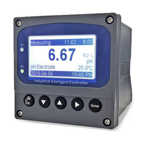
The S504 instruments are digital microprocessor-based units, designed for installation on DIN slot.
All models feature two relay outputs (configurable as control thresholds or alarms), a current (mA) output
fully configurable and galvanically isolated. All outputs may be temporarily disabled (e.g. for
maintenance) using the ON/OFF button. Alarms and errors (diagnostics) are directly shown on display,
and configuration / calibration data are stored into the non-volatile internal memory for at least 10 years.
The S504 series includes models with different analogic input, for the following measurement sensors:
pH / ORP electrode
Two-electrode conductivity cell
Indicator with 0/4-20 mA input (standardized input)
Moreover, all models are equipped with input for PT100 sensor, for temperature measurement and
thermo-compensation of pH and conductivity readings.
Warning! This instrument has been designed to be installed inside an electrical cabinet.
Never use the instrument if it is not correctly mounted and wired!
DESCRIPTION OF THE FRONT PANEL
ON/OFF key Enable / disable output relays
CAL key Allow to enter configuration and calibration modes
[+] key While in normal mode, show the "GAIN" value (amplification factor); in calibration
mode increase the displayed value
[-] key While in normal mode, show the "OFFSET" value (deviation from zero); in
calibration mode decrease the displayed value
NEXT key While in normal mode, toggle between main measure and temperature readings;
in calibration mode exit without saving the new calibration data
LED K1 LED ON = K1 relay ON = contact closed
LED K2 LED ON = K2 relay ON = contact closed
LED ON Light ON (fix) means instrument ON and no anomalies; blinking light indicates
malfunction or outputs disabled through the ON button
Display While in normal operation mode, displays measurement and temperature value.
If no temperature probe is connected, shows the value set in parameter P04, within
brackets.

S504_r2.0 – 09/2022 Page 5
TECHNICAL DATA
Common characteristics
Power supply 10-240 V~ 50/60 Hz (24V- or 24V~ upon request)
Power consumption max 4 VA
Power supply protection internal PTC fuse
Display alphanumeric display, 2 rows x 8 characters, with backlight
Analogue inputs precision better than 0.3% FS ; repeatability better than 0.2% FS
(electronics only)
Temperature input available on all versions; removable, 2-pin terminal block for connection of
a Pt100 sensor
Digital input OFF input for output disabling; accept a voltage free contact (5V supply on
terminals, 5 mA max current)
Digital outputs 2 independent relay outputs on removable, 4-pin terminal block; contact
max load: 250 V∼, 3 A resistive
Current output 0/4-20 mA (selectable through software), 400 Ωmax load, 0.5% FS max
error; galvanic insulation from inputs
Environment Storage temperature -20 to +60 °C
Working temperature -10 to +50 °C
RH max 90% noncondensing
Protection rate IP20
Casing 6 modules, DIN43880 standard, for installation on DIN slot
Dimensions 105 x 90 x h 73 mm
Weight approx. 350 g
Analogic input, depending on model
pH / ORP available on removable, 4-pin terminal block for coaxial cable + reference;
input impedance > 10^12 Ω
Conductivity available on removable terminal block, for connection of a 2-electrode cell
with shield
Standardized input available on removable, 4-pin terminal block (specify input type, measure
range and transducer voltage upon order)

S504_r2.0 – 09/2022 Page 6
ELECTRICAL CONNECTIONS
For electrical connections, always refer to the label attached on the terminal block.
Anyway, the electrical connections of the measure input depend on the instrument model. The following
indications are the common connections for all models:
SUPPLY: pins 1 and 2; the mains power supply must correspond to the instrument voltage (±10%);
see instrument label. The instrument is equipped with an internal protection system, thanks to which
it is not necessary to enforce any polarity in the case of DC power.
OUT K1, K2: pins 3 and 4 are used for relay K1; pins 5 and 6 are dedicated to relay K2.
IN TEMP. PT100: pins 7 and 8 for connecting a Pt100 sensor; in case of long connections (longer
than 5 meters) it is recommended to use a 2-wire shielded cable, and the shield has to be connected
to the pin 8.
IN OFF: pins 9, 10 and 11; voltage free contact to be connected to pins 9 and 10. When the contact
closes, after a set delay, all outputs are disabled and an error message is displayed.
IN ELECTR. : measure input, pins 12, 13, 14 and 15; see specific sections.
OUT mA: current output, pins 8 (positive) and 9 (negative).
Before performing any intervention, ensure that the instrument is not powered!
Notes:
•The relay output contacts are not protected. A fuse or similar protection system must be installed.
•In case of inductive loads the outputs have to be protected with proper systems for the suppression
of arches and interferences (RC networks or varistors for AC voltage, diodes or varistors for DC
voltage).
To obtain a good performance of the device even in noisy environments, it is recommended to follow the
below instructions:
a) Insert a ferrite (code 5062.0020) into the power cable as shown in the picture below
b) Connect the metallic shield of the signal cable to the system grounding or to the REF terminal
c) Insert a ferrite (code 5062.0020) into the input signal cables as shown in the picture below
d) Connect proper RC suppressors (or equivalent) in parallel with the load
e) The electrical cabinet containing the instrument should be correctly grounded
f) If the analogue cable connected to the current output is longer than 20 m, perform the cable shield
grounding (or connection to the REF terminal)
g) Perform one or two turns (if the section of the cable allows it) around the ferrite
Make one or two turns (if the cable section allows it) around the ferrite.
Note: The instrument is supplied with two ferrites, one for the power cable and one for the input signal cable.
In the case of a second input (temperature) with separate cable from that of the main input, order a third ferrite.
2-wire + earth (Y/G)
cable from mains
To the S504
terminal block
Ferrite 5062.0020

S504_r2.0 – 09/2022 Page 7
START-UP
At start-up, the S504 displays the instrument/software version, then checks the status of memorized data
and shows any error or warning messages (see the “Errors” section for details), then the controller enters
the normal mode, displays the measurement value and upgrades the output status.
Pressing simultaneously the [+] and [-] keys at start-up, the S504 runs a “Test” program: the display
shows “0” and the LED ON blinks. This value simulates the measurement and can be incremented or
decremented with the [+] and [-] keys. The “Test” program allows to check the functioning and
configuration of the current and relay outputs.
CONFIGURATION
This section describes the procedure for configuring the editable parameters through front keyboard.
1) Press and hold CAL for at least 2 seconds to enter the
configuration/calibration mode.
2) Press and hold the NEXT key to enter the configuration mode.
3) Release the NEXT key and the display shows the first editable
parameter.
4) The # cursor blinks to indicate that the value can be increased
and/or decreased by pressing the [+] / [-] key.
5) Press CAL to move the cursor and then modify the parameter
value.
6) Adjust the value using the [+] / [-] keys.
7) Press CAL to confirm, or NEXT to exit without saving the
modification.
8) If the modification is confirmed by pressing CAL, the meter
automatically shows the next editable parameter.
9) Repeat the same procedure for all the parameters.
10) Press NEXT to exit the configuration mode and resume normal operation.
Notes:
•If no key is pressed, after a few seconds the instrument automatically exits the configuration
mode.
•If the configuration mode is protected by password, the instrument asks this password before
entering the mode.
E
D
I
T
I
N
G
C
A
L
I
B
R
.
E
D
I T
I N
G
P
A
R
A
M
.
#
M
E
A
T
Y
P
E
0
1
M
E
A
T
Y
P
E
#
0
1

S504_r2.0 – 09/2022 Page 8
LIST OF PARAMETERS
It is recommended to fill the last column with the values set for your application.
Version pH / RX / °C / mA (factory values refer to pH range)
PAR. Description Min
value
Max
value
Default
value
Set
value
P01
Measure type
0
2
0
P02
Reserved
0.00
0.00
0.00
P03
Reserved
0
1
0
P04
Working temperature
0
10
0
25
°C
P05
K1
working mode
0
2
1
P06
Min
threshold of relay
K1
-
1000
2000
6.00 pH
P07
Max threshold of relay
K1
-
1000
2000
6.30 pH
P08
Energizing delay of
K1
0
12
0
0 sec
P09
De
-
energizing delay of
K1
0
12
0
0 sec
P10
K2
working mode
0
4
1
P11
Min threshold of relay K2
-
1000
2000
6.50
pH
P12
Max threshold of relay K2
-
1000
2000
6.80 pH
P13
Energizing delay of K2
0
120
0 sec
P14
De
-
energizing delay of K2
0
120
0 sec
P15
Delay at start
-
up
0
60
0 min
P16
Current output type
0
1
1
P17
Starting value of current output
-
1000
2000
0.00 pH
P18
Full scale value of current output
-
1000
2000
14.00 pH
P19
Current output fault value
0.0
21.0
21.0 mA
P20
Password
0
999
0
P21
Auto
set
0
100
0
(P22)
Measurement 1 starting value
(mA
only
)
-
1000
2000
0
(P23)
Measurement 1 full scale value (mA only)
-
1000
2000
2000
(P24) Decimal point position + measure unit for
measurement 1
(mA
model only
)
0 51 0
Version conductivity meter
PAR. Description Min
value
Max
value
Default
value
Set
value
P01
Conductivity meter type
0
25
2
3
P02
Temperature compensation coeff
icient
0.00
4.00
2.00
P03
Reference temperature
0
1
00
25 °C
P04
Working temperature
0
100
25 °C
P05
K1 working mode
0
2
1
P06 Min threshold of relay K1 -1000 2000
70.0
µ
S
P07 Max threshold of relay K1 -1000 2000
80.0
µ
S
P08
Energizing delay of K1
0
120
0 sec
P09
De
-
energizing delay of K1
0
120
0 sec
P10
K2 working mode
0
4
1
P11 Min threshold of relay K2 -1000 2000
85.0
µ
S
P12 Max threshold of relay K2 -1000 2000
95.0
µ
S
P13
Energizing delay of K2
0
120
0 sec
P14
De
-
energizing delay of K2
0
120
0 sec
P15
Delay at start
-
up
0
60
0 min
P1
6
Current output type
0
60
0 min
P1
7
Starting value of current output
-
1000
2000
-
1000
P1
8
Full scale value of
current output
-
1000
2000
-
1000
P1
9
Current output fault value
0.0
21.0
0.0
P
20
Password
0
999
0
P2
1
Auto set
0
100
0

S504_r2.0 – 09/2022 Page 9
MEANING OF PARAMETERS
PARAMETER 01 (pH / RX / T) MEASURE TYPE
The S504-pH/RX/T is generally supplied already set as pH-meter. Anyway, the user can easily change
this selection as follows: 0 = pH-meter; 1 = redox meter; 2 = thermometer.
PARAMETER 01 (conductivity)CONDUCTIVITY METER TYPE
Select the desired combination of measure range/cell constant and set this parameter accordingly.
See below table for details:
Cell constant
Range
P01
Range
P01
Range
P01
Range
P01
K = 10cm 2µS/cm 1 20µS/cm 2 200µS/cm 3 2000µS/cm 4
K = 1cm 20µS/cm 6 200µS/cm 7 2000µS/cm 8 20mS/cm 9
K = 0.1cm 200µS/cm 11 2000µS/cm 12 20mS/cm 13
200mS/cm 14
K = 0.01cm 2000µS/cm 16 20mS/cm 17 200mS/cm 18
2000mS/cm 19
K = 5cm 2µS/cm 21 20µS/cm 22 200µS/cm 23
2000µS/cm 24
If P01 is set with a value not included in this table, conductivity measurements will be not reliable.
PARAMETER 01 (mA input) MEASURE TYPE
This parameter allows to choose the standardized input type as follows: 0= 0-20 mA; 1 = 4-20 mA.
PARAMETER 02 (pH/RX/T / mA input) RESERVED
Reserved for future use.
PARAMETER 02 (conductivity) TEMPERATURE COMPENSATION COEFFICIENT
Temperature compensation is calculated as follows:
αT
C(T) = C(T
ref
) x 1 + ─── x (T – T
ref
)
100
Where: T = current temperature value (°C)
T
ref
= reference temperature (typically 25°C, or value set in parameter P03)
αT = temperature compensation coefficient, in %/°C (P02)
The typical temperature compensation coefficient is αT=2.00%/°C. Typical αT values depend on the
solution: Acid: 1.0 to 1.6 %/°C
Alkali: 1.8 to 2.2 %/°C
Salt: 2.2 to 3.0 %/°C
Water: approx. 2.0 %/°C
The αT coefficient is not strictly constant over the whole range of thermo-compensation, but for small
temperature variations (e.g. 20-50°C) it can be considered constant. Setting this coefficient to 0 means
no temperature compensation.
If the αT value is unknown, it can be calculated as follows:
1) Set αT (P02) to 0.00 (no temperature compensation)
2) Read the conductivity value of the liquid at the reference temperature (e.g. 25°C)
3) Bring the liquid at the working temperature
4) Read the conductivity value at the working temperature
5) Calculate the αT (P02) coefficient with the following formula:
C(T) – C(T
ref
) 100
αT = ─────────- x ─────
T - T
ref
C(T
ref
)
6) Enter the calculated coefficient in the parameter P02
PARAMETER 03 (pH/RX/T / mA input) RESERVED
Reserved for future use.

S504_r2.0 – 09/2022 Page 10
PARAMETER 03 (conductivity) REFERENCE TEMPERATURE
See Parameter 02
PARAMETER 04 WORKING TEMPERATURE
All S504 models can measure the temperature and use the value for temperature compensation of
measurements. If no Pt100 sensor is connected, this parameter allows to enter the working temperature
value, which is displayed in brackets.
PARAMETER 05 K1 WORKING MODE
The K1 relay output features 3 different working modes, coded as follows:
0 = the relay is disabled (always OFF)
1 = the contact is closed when the set thresholds are exceeded
2 = the contact is open when the set thresholds are exceeded
PARAMETER 06 MIN THRESHOLD OF RELAY K1
Minimum threshold for the intervention of relay K1, accordingly with the above indications.
PARAMETER 07 MAX THRESHOLD OF RELAY K1
Maximum threshold for the intervention of relay K1, accordingly with the above indications.
PARAMETER 08 ENERGIZING DELAY OF RELAY K1
If the relay K1 is configured for working mode 1 or 2, this parameter allows to enter a delay (in seconds)
for its activation. Setting P08 to zero excludes the delay (immediate activation of the relay).
PARAMETER 09 DE-ENERGIZING DELAY OF RELAY K1
Same as parameter 09, but referred to the relay de-activation.
PARAMETER 10 K2 WORKING MODE
The K2 relay output features 6 different working modes, coded as follows:
0 = the relay is disabled (always OFF)
1 = the contact is closed when the set thresholds are exceeded
2 = the contact is open when the set thresholds are exceeded
3 = NC (normally closed) alarm, i.e. the contact K2 is closed when measurement is within the set
thresholds (P11 & P12).
4 = NO (normally open) alarm, i.e. the contact K2 is open when measurement is within the set
thresholds (P11 & P12).
5 = automatic cleaning cycle, i.e. at preset intervals, the instrument freezes the measurement,
activates the K2 relay (to which, for example, a solenoid valve is connected, that regulates the
dosage of detergent) for a set time; then deactivates K2 and keeps the measurement frozen for the
time necessary to complete the wash; finally it resumes to normal operation.
P10=5
K2
Measure
hold
Param.
P11 P12 P13 P11 P12 P13
Pause time Clean
time
Measure
hold Pause time Clean
time
Measure
hold
PARAMETER 11 MIN THRESHOLD OF RELAY K2
This is the minimum threshold for the activation of relay K2, or the pause time between two subsequent
cleanings as explained above.
PARAMETER 12 MAX THRESHOLD OF RELAY K2
This is the maximum threshold for the activation of relay K2, or the cleaning time as explained above.
PARAMETER 13 ENERGIZING DELAY OF RELAY K2
This parameter allows to enter a delay time (in seconds) for the activation of relay K2, or the
measurement hold time (in seconds) after a cleaning action.

S504_r2.0 – 09/2022 Page 11
PARAMETER 14 DE-ENERGIZING DELAY OF RELAY K2
This parameter allows to enter a delay time (in seconds) for the de-activation of relay K2.
PARAMETER 15 DELAY AT START-UP
At start-up, the sensor connected to the signal input could need a stabilization time before giving correct
measurements. For example, this is a typical behavior for the redox electrodes immersed in oxidized
solution. If no delay is set, during stabilization the instrument activates the outputs depending on the
measured value and can, therefore, perform erroneous actions due to unstable readings.
This parameter allows to enter a correct delay (in minutes) to keep the instrument in stand-by during
measurement stabilization. If the parameter is set to zero, this function is disabled.
PARAMETER 16 CURRENT OUTPUT TYPE
This parameter allows to enter the desired mA range for the current output: 0 = 0-20 mA ; 1 = 4-20 mA.
Note: The declared precision of the current output applies to values greater than approx. 0.3 mA, while
at the beginning of the 0-20 mA the precision is decreased at 1.5%.
PARAMETER 17 STARTING VALUE OF CURRENT OUTPUT
This parameter is used to set the measurement value to which corresponds the starting point of the
current output (0 or 4 mA depending on the configuration of the parameter P16).
For example, in the case of pH measurement and P16=1, to obtain 4 mA at 3.50 pH, set P17 to 3.50.
PARAMETER 18 FULL SCALE VALUE OF CURRENT OUTPUT
This parameter is used to set the measure value to which corresponds the full scale value of the current
output (20 mA). For example, in case of pH measurement, to obtain 20 mA at 8.40 pH, set P18 to 8.40.
PARAMETER 19 FAULT VALUE OF CURRENT OUTPUT
This parameter allows to set the fault value of the current output (e.g. over-range error, measurement
disabled by the OFF input, ON/OFF key pressed, etc.).
PARAMETER 20 PASSWORD
To protect the access to the configuration menu with a password and prevent undesired modification by
non-authorized personnel, enter a value different from zero in this parameter.
Warning! If the password is forgot, there is no way to access the configuration menu! The instrument has
to be sent to the manufacturer for a complete re-configuration!
PARAMETER 21 AUTO SET
This parameter allows to restore all default values for the configuration parameters (P01 to P20). This
operation can be useful when unreliable values have been entered. To activate the reset operation, enter
“12”. When the AUTOSET is completed, the instrument displays a message to inform the user.
(PARAMETER 22) MEASUREMENT 1 STARTING VALUE
This parameter is available for models with mA input and represents the displayed value correspondent
to the starting value of the current output span (0 or 4 mA). Normally this parameter is factory set
accordingly with customer indications. Do not attempt to modify this value!
(PARAMETER 23) MEASUREMENT 1 FULL SCALE VALUE
This parameter is available for models with mA input and represents the displayed value correspondent
to the full scale value of the current output span (20 mA). This parameter is factory set accordingly with
customer indications. Do not attempt to modify this value!
(PARAMETER 24) DECIMAL POINT POSITION AND MEASURE UNIT FOR MEAS.1
This parameter is available for models with mA input and allows to set the decimal point position on
display and the desired measure unit, accordingly with the following formula:
P24 = (Measure unit code x 8) + Decimal point position
Note: Normally this parameter is factory set accordingly with customer indications. Do not attempt to
modify this value!

S504_r2.0 – 09/2022 Page 12
Codified measure unit are listed in the table below:
0 = 1 = pH 2 = mV 3 = °C 4 = ppm 5 = uS 6 = mS 7 = % 8 = mA
9 =
pulse
10 = sec
11 = min
12 =
%/°C
13 = V
14=m
bar
15 =
bar
16 = cm
17 = m
18
=
FTU
19 = NTU
20 = l/h
21 = m
3
/h
Example: 4-20 mA input from remote conductivity meter with measure range 0…50.0 mS/cm:
P1 = 1 ; P22 = 0 ; P23 = 500 ; P24 = (6x8)+1 = 49
CONTROL EXAMPLES
Here below are listed some typical configuration examples for the control parameters:
1) S504 pH/RX version; control of the acidification to obtain a pH level of 7.40 :
MEASURE TYPE = 0 (pH-meter) (P01 = 0)
K1 WORKING MODE = 1 (relay closes when max threshold is exceeded) (P05 = 1)
It is recommended to set a quite narrow hysteresis window, for example:
MIN THRESHOLD = 7.30 pH (P06 = 7.30 pH)
MAX THRESHOLD = 7.50 pH (P07 = 7.50 pH)
In this condition the relay K1 is energized (and activates the acidification) when the pH level is greater
than 7.50, and de-energizes as soon as the pH level falls below 7.30.
The relay K2 can be used as an alarm threshold:
K2 WORKING MODE = 3 (NC alarm) (P10 = 3)
MIN THRESHOLD = 6.50 pH (P11 = 6.50 pH)
MAX THRESHOLD = 8.50 pH (P12 = 8.50 pH)
2) Check the conductivity of the water coming out from a demineralization plant, and generate an alarm
(or trigger a resin regeneration cycle) when the conductivity level is greater than 12.00 µS/cm. Set the
conductivity range and K1 parameters as follows:
CONDUCTIVITY METER TYPE = 22 (19.99 µS/cm, K = 5 cm) (P01 = 22)
K1 WORKING MODE = 1 (relay closes when threshold is exceeded) (P05 = 1)
MIN THRESHOLD = 12.00 µS/cm (P07 = 12.00 µS/cm)
ENERGIZING DELAY = 60 sec (P08 = 60 sec)
DE-ENERGIZING DELAY = 0 sec (P09 = 0 sec)
In this condition the relay K1 is energized (generating an alarm or triggering a regeneration cycle) as
soon as the conductivity level exceeds the 12.00 µS/cm threshold for at least 1 minute (60 sec). This
delay avoids erroneous commands due to interferences or momentary peaks.
TEMPERATURE COMPENSATION
The temperature compensation of pH and conductivity measurements is performed using the
temperature read through the temperature input. If no temperature probe is connected, the S504 uses -
as working temperature - the value set in the parameter P04.

S504_r2.0 – 09/2022 Page 13
ADDITIONAL VISUALIZATIONS
Pressing the [-] and [+] keys during the normal operations will result in the following displaying:
pH-meter [+] gain factor (0.667 ... 1.428)
[-] offset in pH units @25°C (-1.50 ... 1.50)
Redox-meter [+] gain factor (1.000) - fix
[-] offset in mV (-150 ... 150)
Thermometer [+] gain factor (0.900 … 1.100)
[-] offset in °C (-5.0 … +5.0°C)
Conductivity meter [+] gain factor (0.750 ... 1.500)
[-] offset in points (-100 ... 100)
Std. input [+] gain factor (0.500 ... 2.000)
[-] offset in points (-200 ... 200)
Note: With the factory calibration these values are set as following: OFFSET = 0 , GAIN = 1.000.
ERRORS
Each error or anomaly detected by the controller generates a warning message on the display, the
blinking LED ON and the fault value (P19) at the current output. Error messages are listed here below.
WARNING 01 : K1 DISABLED
No working mode has been set for output K1, but the instrument continues its normal operations.
WARNING 02 : K2 DISABLED
No working mode has been set for output K2, but the instrument continues its normal operations.
ERROR 02 : mA OUTPUT ERROR
The mA output range has been set with min and max thresholds too close (P17 and P18). In this condition
the mA output does not work properly. Re-set parameters P17 and P18.
CALIBRATION ERROR!
Calibration cannot be completed successfully (for example pH offset calibration with electrode immersed
in pH4 buffer solution). Repeat the procedure and carefully check electrode, cable and calibration
solutions.
OFF LIV. FLOW
Missing consent at the related input (terminals 9, 10 and 11) . This input is typically connected to a level
or flow control. Restore level or flow. When this error is active, all outputs are disabled.
UR / OR : Under / Over Range
The input signal is lower / greater than the minimum / maximum measurement limit for the instrument.
Check the sensor connected to the input and the connection cable. When this error is active, all outputs
are disabled.

S504_r2.0 – 09/2022 Page 14
SPECIFICATIONS OF pH INPUT
ELECTRICAL CONNECTIONS
The signal comes from the electrode through a coaxial cable, with a maximum recommended length of
20 meters (for longer cables, please contact the manufacturer).
The electrode input is available on terminals 12 and 13: connect the shield to the pin 12 and the core of
the coaxial cable to the pin 13 (Note: remove any black conductive plastic between the core and shield
of the cable).
If separated measure and reference electrodes are used, connect reference electrode to pin 14 (REF).
The Pt100 temperature sensor input is available on terminals 7 and 8. Immerse the Pt100 probe into the
liquid to be tested, close to the electrode or anyway at the same temperature. If a 3-wire sensor I used,
connect the 2 wires of the same color to the same terminal (the wires are internally short circuited).
Caution! Always keep signal cables away from power cable!
ELECTROCHEMICAL CALIBRATION
Before starting this procedure, ensure to have fresh buffer solutions (not expired). If temperature
compensation is used, immerse the Pt100 probe into the buffer solutions together with the measure
electrode.
1.
Rinse the electrode with distilled water.
2.
Immerse the electrode in pH 7.01 buffer solution.
3.
Press and hold the CAL key for at least 2 seconds to enter the
calibration mode.
4.
Press [-] and the “OFFSET” message is displayed.
5.
Release the button and the display will show the buffer pH value,
automatically recognized.
6.
If necessary, adjust the value using the [+] or [-] key.
7.
Press CAL to confirm the calibration, or press NEXT to exit
without saving (previous calibration data are kept).
8.
Rinse the electrode with distilled water.
9.
Immerse the electrode in pH 4.01 (or pH 9.01) buffer solution.
10.
Press and hold the CAL key for at least 2 seconds to enter the
calibration mode.
11.
Press [+] and the “GAIN” message is displayed.
12.
Release the button and the display will show the buffer pH value,
automatically recognized.
13.
If necessary, adjust the value using the [+] or [-] key.
14.
Press CAL to confirm the calibration, or press NEXT to exit
without saving (previous calibration data are kept).
The instrument does not automatically recognizes the buffer pH values whenever:
a) The buffer solution is contaminated dirty or expired
b) The electrode is not working properly or it is exhausted
c) The electrode connection cable is damaged
Note: If you attempt to calibrate the offset at a pH value too different from pH 7, or to calibrate the gain
with a buffer solution too close to pH neutrality, the instrument shows the <<Cal error!>> message and
does not save the calibration data.
E
D
I
T
I
N
G
C
A
L
I
B
R
.
O
F
F
S
E
T
C
A
L
I
B
R
.
O
F
F
S
E
T
7
.
0
1
p
H
E
D
I
T
I
N
G
C
A
L
I
B
R
.
G
A
I
N
C
A
L
I
B
R
.
G
A
I
N
4
.
0
1
p
H

S504_r2.0 – 09/2022 Page 15
SPECIFICATIONS FOR ORP INPUT
ELECTRICAL CONNECTIONS
The signal comes from the electrode through a coaxial cable, with a maximum recommended length of
20 meters (for longer cables, please contact the manufacturer).
The electrode input is available on terminals 12 and 13: connect the shield to the pin 12 and the core of
the coaxial cable to the pin 13 (Note: remove any black conductive plastic between the core and shield
of the cable).
If separated measure and reference electrodes are used, connect reference electrode to pin 14 (REF).
If temperature measurement is also required, connect a Pt100 temperature sensor to terminals 7 and 8.
If a 3-wire Pt100 sensor is used, connect the 2 wires of the same colour at the same terminal (the wires
are internally short circuited).
Caution! Always keep signal cables away from power cable!
ELECTROCHEMICAL CALIBRATION
Before starting the procedure, check to have a fresh calibration solution (not expired).
1.
Rinse the electrode with distilled water.
2.
Immerse the electrode into a calibration solution of known value
(e.g. 230 mV)
3.
Press and hold the CAL key for at least 2 seconds to enter the
calibration mode.
4.
Press [-] to display the “OFFSET” message.
5.
Release the button and the display will show the calibration
solution value (mV).
6.
If necessary, adjust the displayed value using the [+] or [-] key.
7.
Press CAL to confirm the calibration, or press NEXT to exit without
saving (previous calibration data are kept).
After performing the calibration, the meter does not display the standard solution value whenever:
a) The calibration solution is contaminated dirty or expired
b) The electrode is not working properly or it is exhausted
c) The electrode connection cable is damaged
Note: If you attempt to calibrate the offset at a value too different from the internal one, the instrument
shows the << Cal error!>> message and does not save the calibration data.
ORP calibration is a single point procedure (offset)!
E
D
I
T
I
N
G
C
A
L
I
B
R
.
O
F
F
S
E
T
C
A
L
I
B
R
.
O
F
F
S
E
T
2
4
3
m
V

S504_r2.0 – 09/2022 Page 16
SPECIFICATIONS OF TEMPERATURE INPUT
ELECTRICAL CONNECTIONS
The signal comes from a Pt100 sensor through a 2 or 3-wire cable, that has to be shielded if longer than
15 meters. Connections are made on removable terminal block, at pins 7 and 8.
If a sensor with 3-wire cable is used, connect to the same terminal the two wires of the same colour
(internally short-circuited). If a shielded cable is used, connect the shield to terminal 14 (REF).
THERMOMETER CALIBRATION
The electronic calibration of the instrument and the accuracy class of the Pt100 sensor ensure a
maximum error of ±0.3°C at 0°C and ±0.8°C at 100°C (Pt100 class B, according to IEC 751 standard).
Therefore, no user calibration is required.
Note: Factory calibration is performed with a sensor with 2 m cable. Using a probe with a cable longer
than 2 meters could introduce a greater reading error.

S504_r2.0 – 09/2022 Page 17
SPECIFICATIONS OF CONDUCTIVITY INPUT
ADDITIONAL TECHNICAL INFO
The electronic precision of the conductivity measurements is better than 1%, and the repeatability is
better than 0.2% FS, without temperature compensation (resistive calibration). The temperature
compensation introduces an additional error of 0.3% FS, and is performed through the PT100 input.
The temperature sensor may be a probe separated from the conductivity cell (e.g. PT100S), or a built-
in sensor (e.g. CCK5TC). For further details, refer to the technical documentation supplied with the cell.
ELECTRICAL CONNECTIONS
The signal comes from the 2-electrode cell, to be connected to terminals 12 and 13; if a shielded cable
is used, connect the shield to terminal 14 (GND). In case of low conductivity measurement, it is
recommended to use a shielded cable.
The Pt100 sensor input is at terminals 7 and 8. If no temperature probe is connected, the instrument
uses a constant working temperature of 25.0°C. If a Pt100 probe is used, immerse it in the liquid to be
tested, close to the cell or anyway at the same temperature.
To avoid interferences and measure errors due to parasitic capacity of the cable, it is recommended to
use a cell connection cable as short as possible. Do not extend the supplied cable; if a longer cable is
needed, please contact the manufacturer.
Caution! Always keep signal cables away from power cable!
ELECTRICAL CALIBRATION
To test the proper functioning of the instrument, connect to the cell input a resistive simulator. Set an
infinite resistor value and the meter should display “0”. To calculate the resistor value to be entered for
simulating a given conductivity value, use the following formula:
1 1 Rcell = simulation resistor
Rcell = ──────── MΩ= ─-──--───── Cond = conductivity value to be simulated
(Cond x K) (µS/cm x cm) K = cell constant
Notes:
•To verify the correct visualization, also consider the set “gain” factor. To view the gain value, press
the [+] key.
•The temperature should be approx. 25°C; if not, leave terminals 24 and 25 not connected.
ELECTROCHEMICAL CALIBRATION
The electrochemical calibration allows to compensate errors due to the cell-instrument connection cable
and to the mechanical error of the cell constant. If the temperature compensation feature is used,
immerse the Pt100 sensor into the solution close to the cell, or anyway at the same temperature.
1. Leave the cell in air.
2. Press and hold CAL for at least 2 seconds to enter the calibration
mode.
3. Press [-]: the OFFSET message is displayed, and then “0” value.
4. The zero value with cell in air is generally not adjusted, but - if
necessary - use the [+] and [-] keys.
O
F
F
S
E
T
C
A
L
I
B
R
.
E
D
I
T
I
N
G
C
A
L
I
B
R
.

S504_r2.0 – 09/2022 Page 18
5. Press CAL to confirm calibration, or NEXT to exit without saving
(previous calibration data are kept).
6. Immerse the cell into a standard conductivity solution (see the table
below).
7. Press and hold CAL for at least 2 seconds to enter the calibration
mode.
8. Press [+]:the “GAIN” message is displayed, and then the previous
measurement or a known standard value automatically
recognized.
9. If necessary, adjust this value using the [+] / [-] keys.
10. Press CAL to confirm calibration, or NEXT to exit without saving
(previous calibration data are kept).
Note: If you attempt to calibrate using an offset value too different from the range minimum value or a gain
value with a too low input signal, the instrument shows the << Cal error!>> message and does not save
the calibration data.
Conductivity values of KCl (potassium chloride) solutions:
Temp.
(°C)
KCl 1 N
(µS/cm)
KCl 0.1 N
(µS/cm)
KCl 0.01 N
(µS/cm)
0 65410 7150 776
5 74140 8220 896
10 83190 9330 1020
15 92540 10480 1147
16 94430 10720 1173
17 96330 10950 1199
18 98240 11190 1225
19 100160 11430 1251
20 102090 11670 1278
21 104020 11910 1305
22 105940 12150 1332
23 107890 12390 1359
24 109840 12640 1386
25 111800 12880 1413
26 113770 13130 1441
27 115740 13370 1468
28
13620 1496
29
13870 1524
30
14120 1552
O
F
F
S
E
T
0
0
u
S
E
D
I
T
I
N
G
C
A
L
I
B
R
.
G
A
I
N
C
A
L
I
B
R
.
G
A
I
N
1
4
1
3
u
S

S504_r2.0 – 09/2022 Page 19
SPECIFICATIONS OF STANDARDIZED INPUT
ELECTRICAL CONNECTIONS
The signal comes from the transmitter (or transducer) through a 2 or 3-pole cable, that has to be shielded
if longer than 20 meters.
Connections are made on removable terminal block as follows:
1. Passive transducer: terminal 14 = negative input (IN-)
terminal 13 = positive input (IN+)
terminal 12 = power supply positive (+Va)
2. Active transmitter: terminal 13 = positive input (IN+)
terminal 14 = negative input (IN-)
3. 2-wire passive transmitter:
terminal 12 (power supply) = positive input (+Va)
terminal 14 = negative input (IN-)
If a shielded cable is used, connect the cable shield to terminal 14 (S504 side) and leave it disconnected
on the transmitter side.
ELECTRICAL CALIBRATION
Errors due to instrument (S504) and transducer are typically very small and no calibration is required.
However, in case of pressure transducer converted into piezometric levels, sometimes zero and gain
calibrations are needed; proceed as explained here below.
1. Set the transmitter to have the minimum range signal (e.g. 0 or 4 mA).
2. Press and hold CAL for at least 2 seconds to enter the calibration
mode.
3. Press [-]: the OFFSET message is displayed, and then the
measurement value.
4. If necessary, adjust this value using the [+] / [-] keys.
5. Press CAL to confirm calibration, or NEXT to exit without saving
(previous calibration data are kept)
6. Set the transmitter to have the full scale signal (or a signal greater
than the 70% of the range).
7. Press and hold CAL for at least 2 seconds to enter the calibration
mode.
8. Press [+]: the GAIN message is displayed, and then the previous
measurement.
9. If necessary, adjust this value using the [+] / [-] keys.
10. Press CAL to confirm calibration, or NEXT to exit without saving
(previous calibration data are kept).
Note: If you attempt to calibrate using an offset value too different from the range minimum value or a
gain value with a too low input signal, the instrument shows the << Cal error!>> message and does not
save the calibration data.
O
F
F
S
E
T
2
.
3
m
O
F
F
S
E
T
C
A
L
I
B
R
.
E
D
I
T
I
N
G
C
A
L
I
B
R
.
E
D
I
T
I
N
G
C
A
L
I
B
R
.
G
A
I
N
C
A
L
I
B
R
.
G
A
I
N
3
8
.
7
m
Table of contents
Other Steiel Controllers manuals
