Balluff BNI PBS-504-001-K008 User manual

BNI PBS-504-001-
K008
BNI PBS-504-002-
K008
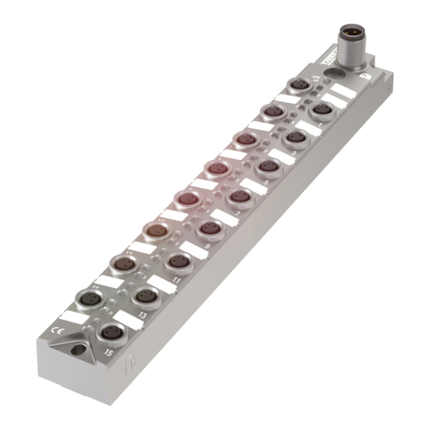
Profibus IO-Link Panel
master
User´s Guide

www.balluff.com
1
Table of Contents
1Notes for the user 2
1.1. Structure of the guide 2
1.2. Typografical conventions 2
Enumerations 2
Actions 2
Syntax 2
Cross references 2
1.3. Symbols 2
1.4. Abbreviations 2
1.5. Deviating views 2
2Safety 3
2.1. Intended use 3
2.2. Installation and startup 3
2.3. General safety instructions 3
2.4. Resistance to aggressive substances 3
Hazardous voltage 3
3Basic Knowledge 4
3.1. Product description 4
3.2. Profibus 4
3.3. IO-Link 4
3.4. Communication mode 5
Standard IO-modes (SIO-mode) 5
3.5. Replacing modules 5
4Getting started 6
4.1. Connection overview BNI PBS-504-00x.. 6
4.2. Mechanical connection 7
4.3. Electrical connection 8
Power supply 8
Function earth 8
Profibus Interface 9
Adressing 9
4.4. Conneting sensors / actuators 10
IO-Link port 10
5Technical Data 11
5.1. Dimensions Front side 11
5.2. Dimensions Cutout Backside 11
5.3. Mechanical data 11
Electrical Data 12
Operating conditions 12
5.4. Function indicators LED 13
Module status 13
I/O- und IO-Link ports 13
6Appendix 14
6.1. Included material 14
6.2. Ordercode 14
6.3. Order information 14

Balluff Network Interface Profibus, BNI PBS-504-00x-K008
www.balluff.com
2
1 Notes for the user
1.1. Structure of the
guide
The guide is organized so that the sections build on one another.
Section 2: Basic safety information.
Section 3: Getting started.
…….
1.2. Typografical
conventions
The following typographical conventions are used in this Guide.
Enumerations
Enumerations are shown in list form with indent.
−Entry 1,
−Entry 2.
Actions
Action instructions are indicated by a preceding triangle. The result of an action is indicated
by an arrow.
Action instruction 1
Action result
Action instruction 2
Syntax
Numbers:
Decimal numbers are shown without additional indicators (e.g. 123).
Hexadecimal numbers are shown with the additional indicator hex (e.g. 00hex).
Cross references
Cross references indicate where additional information on the topic can be found.
1.3. Symbols
Attention!
This symbol indicates a security notice which most be observed.
Note
This symbol indicates general notes..
1.4. Abbreviations
AUX
O-Port
BCD
BNI
EMC
I-Port
FE
GSD
LSB
MSB
SELV
PLC
PELV
Profibus DP
IOL
AUX power (auxiliary power)
Digital output port
Binär coded switch
Balluff Network Interface
Electromagnetic compatibility
Digital input port
Functions earth
Generic Station Description
Least Significant Bit
Most Significant Bit
Safety Extra Low Voltage
Process logic control
Protective Extra Low Voltage -
Profibus DP: Profibus dezentrale peripherie
IO-Link
1.5. Deviating views
Product views and illustrations in this guide may differ from the actual product. They are
intended only as illustrative material.

www.balluff.com
3
2 Safety
2.1. Intended use
This guide describes The BNI PBS-… serves as a decentralized input/output module for
connecting to a Profibus network. The integrated IO-Link ports enable simple linking of IO-
Link capable sensors, actuators and sensor / actuator hubs. The module may be used only
for this purpose in an industrial environment corresponding to Class A of the EMC Law.
Via PIN 2/5 Power Aux (Auxiliary power) function provides 24V DC power supply for
actuators.
2.2. Installation and
startup
Attention!
Installation and startup are to be performed only by trained specialists. Qualified
personnel are persons who are familiar with the installation and operation of the
product, and who fulfills the qualifications required for this activity. Any damage
result
ing from unauthorized manipulation or improper use voids the
manufacturer's guarantee and warranty. The Operator is responsible for ensuring
that applicable of safety and accident prevention regulations are complied with.
2.3. General safety
instructions
Commissioning and inspection
Before commissioning, carefully read the user's guide.
The system must not be used in applications in which the safety of persons is dependent
upon proper functioning of the device.
Authorized personnel
Installation and startup must only be carried out by trained technical personnel.
Intended use
Warranty and liability claims against the manufacturer are rendered void by:
−Unauthorized tampering
−Improper use
−Use, installation or handling contrary to the instructions provided in this user's
manual
Obligations of the operating company
The device is a piece of equipment in accordance with EMC Class A. This device can
produce RF noise. The operator must take appropriate precautionary measures. The device
may only be used with an approved power supply. Only use approved cables.
Malfunctions
In the event of defects and device malfunctions that cannot be rectified, the device must be
taken out of operation and protected against unauthorized use.
Intended use is ensured only when the housing is fully installed.
2.4. Resistance to
aggressive
substances
Attention!
The BNI modules generally have a good chemical and oil resistance. When used
in aggressive media (eg chemicals, oils, lubricants and coolants each in high
concentration (ie, low water content)) must be checked prior application-related
material compatibility. In the event of failure or damage to the BNI modules due
to such aggressive media are no claims for defects
Hazardous
voltage
Attention!
Disconnect all power before servicing equipment.
Note
In the interest of product improvement, the Balluff GmbH reserves the right to
change the specifications of the product and the contents of this manual at any
time without notice.

Balluff Network Interface Profibus, BNI PBS-504-00x-K008
www.balluff.com
4
3 Basic Knowledge
3.1. Product
description
Balluff Network Interface BNI PBS-...:
•Used for connecting sensors/actuators to a Profibus-DP network.
•Sensors/actuators can be connected through 4 standard I/O ports.
Connection options:
A total of 8 ports are available which can be freely configured. If for example 4 IO-Link ports
are configured, 4 standard I/O ports can be used.
BNI PBS-504-...: Max. 8 standard I/O-ports and/or max.4 IO-Link ports, freely configurable.
The main areas of application are:
•In the industrial area as an interface between sensors/actuators and a Profibus.
•When using "intelligent" sensors and actuators which process information in
addition to the actual process signal (e.g. diagnostics information).
•Shall not be used in Profibus networks where repeater-modules ared used.
BNI PBS 504-002-K008 should be used in these networks instead.
3.2. Profibus
Open bus system for process and field communication in cell networks with a low number of
stations as well as for data communication per IEC 61158/EN 50170. Automation devices
such as PLC's, PC's, control and monitoring devices, sensors or actuators can
communicate over this bus system.
Variants:
•Profibus DP for fast, cyclical data exchange with field devices,
•Profibus PA for applications in process automation in the intrinsically safe area,
•Profibus FMS for data communication between automation devices and field
devices.
3.3. IO-Link
IO-Link is defined as a standardized point-to-point connection between sensors/actuators
and the I/O module. An IO-Link sensor/actuator can send additional communication data
(e.g. diagnostics signas) in addition to the binary process signas over the IO-Link interface.
Compatibility with standard I/O:
•IO-Link sensors/actuators can be connected to existing I/O modules.
•Sensors/actuators which are not IO-Link capable can be connected to an IO-Link
module.
•Standard sensor/actuator cable can be used.
Key technical data:
•Serial point-to-point connection,
•Communication as add-on to standard I/O.
•Standard I/O connection technique, unshielded, 20m cable length.
•Communication using 24V pulse modulation, standard UART protocol.
•Maximum current draw: per sensor 200 mA/per actuator 1,6 A.

www.balluff.com
5
3 Basic Knowledge
3.4. Communication
mode
Process data (cyclical):
The GSD file provides different data modules for representing the sensor map:
•Inputs: 1 byte – 32 bytes
•Outputs: 1 byte – 32 bytes
•Or combined input/output modules
Deterministic time behavior:
•Typically 2 ms cycle time 16 bits of process data and 38.4 Kbaud
transmission rate.
Service data (diagnostics, parameters):
•parallel and reactionless process data
Standard IO-
modes (SIO-
mode)
•Startup parameter setting possible using communication, then
•binary switching signal
3.5. Replacing
modules
The BNI PBS-... modules are upward compatible. A defective module can be
replaced with a module which has a greater or at least the same functionality.

Balluff Network Interface Profibus, BNI PBS-504-00x-K008
www.balluff.com
6
4 Getting started
4.1. Connection
overview BNI
PBS-504-00x..
1 Input / Output / IO-Link port 1
2 LED: Input / Output / IO-Link port
3 Input / Output / IO-Link port 3
4 IO-Link logo
5 Input / Output / IO-Link port 2
6 Label
7 Status LEDs Module and bus communication
8 Input / Output / IO-Link port 0
1
2
3
4
5
6
7

www.balluff.com
7
4 Getting started
4.2. Mechanical
connection
The module BNI PBS-504… is attached using 4 M5x10.
The thread insert for mounting the module is 8mm.
1 Mounting holes with 8mm thread insert
2 Ground connection
3 Power supply interface, terminal plugs
4 Address switches
5 Profibus interface Sub D 9 pole
6 Grommet
5
4
1
1
2
5
6
6
2
3

Balluff Network Interface Profibus, BNI PBS-504-00x-K008
www.balluff.com
8
4 Getting started
4.3. Electrical
connection
Power supply
The power supply is connected to terminal plugs, spring type on the back side of the unit.
Pin
Function
Description
6
24V Bus communication /
Sensor supply
5
4
0V Bus communication /
Sensor supply
3
2
+24 V DC, max. 12 A, AUX
AUX Power
1
0V, AUX
GND AUX Power
Pin 1 and 2: internal bended
Pin 3 and 4: internal bended
Pin 1 and 5: no fuse inside, external protection requested
Note
Pin 5 power supply, external protection (fuse) requested.
Function earth
Note
The FE connection from the housing to the machine must be low-impedance and kept
as short as possible
6
5
4
3
2
1

www.balluff.com
9
4 Getting started
Profibus Interface
The bus connection is made using the SUBD 9-Pin female connector.
The address is set on the address switch.
Profibus (SUB-D 9, female)
Note
- Continuation of the Profibus by SUB-D9 Pin connectors.
Note
Each Profibus segment end must be installed with a termination resistor.
Unused sockets must be fitted with over caps to ensure IP54 protecting rating.
Pin
Function
1
Protection ground
2
Not connected
3
A line
4
Not connected
5
GND Data
6
5V power for bus terminator
7
Not connected
8
B line
9
Not connected
Adressing
The Profibus address is et directly on the BNI PBS-504…
using two BCD switches
Permissible address range: 0 … 99.
Each Profibus node must have a unique address assigned
to it.
Any change to the address does not become effective until
power is reset on the modules.
x10
x1

Balluff Network Interface Profibus, BNI PBS-504-00x-K008
www.balluff.com
10
4 Getting started
4.4. Conneting
sensors /
actuators
Four I/O ports are provided for connecting the actuators / sensors for Standard I/O and/or IO-Link
IO-Link port
M12, A-coded,female
Pin
Function
1
+24 V DC, 1,4 A
2
AUX Power, 24 V
3
0 V
4
IO-Link / Eingang /Ausgang (max.1.4 A)
5
AUX Power GND, 0V
Note
Unused I/O port socket must be fitted with cover caps to ensure IP54 protection
rating.

www.balluff.com
11
5 Technical Data
5.1. Dimensions
Front side
5.2. Dimensions
Cutout
Backside
5.3. Mechanical
data
Housing material
Plastic
Fieldbus
Profibus: SUB-D 9 Pin (female)
Supply power
Terminal plugs, spring type (on the backside)
AUX power supply
Terminal plugs, spring type (on the backside)
I/O Ports
M12, A coded (4 x female )
Enclosure rating
Front side: IP54
(only when installed, plugged-in and threaded-in)
Back side: IP20
Weight
ca.: 355 g

Balluff Network Interface Profibus, BNI PBS-504-00x-K008
www.balluff.com
12
5 Technical Data
Electrical
Data
Operating voltage
18 ... 30 V DC
Operation voltage AUXPower
18 ... 30 V DC, 12A
Ripple
< 1 %
Current draw without load
≤ 200 mA
Operating
conditions
Ambient temperature
Storage temperature
-5
C … 55°C
-25
C … 70°C

www.balluff.com
13
5 Technical Data
5.4. Function
indicators LED
Module status
LED
Indicator
Function
LED 1
Green
Red
US Power supply sensors / Bus communication ok
US Power supply sensors / Bus communication under voltage
LED 2
Green
AUX power supply connected
LED 3
Green, solid
Green, blinking
BUS Data transmission active
BUS Data transmission inactive
I/O- und IO-Link
ports
Jedem M12-Port (IO-Link, E/A-Schnittstelle) sind LEDs zugeordnet um die
Betriebszustände anzuzeigen.
Anzeige
LED 4 (PIN 4)
Aus
Ausgang = 0
Eingang = 0
Gelb
Ausgang = 1
Eingang = 1
Grün
IO-Link: Kommunikation
Grün
blinkend
IO-Link: keine Kommunikation
Rot
I Ausgang > Imax
Eingang: KS*
IO-Link: Kommunikationfehler
LED 4
LED 3
LED 2
LED 1

Balluff Network Interface Profibus, BNI PBS-504-00x-K008
www.balluff.com
14
6 Appendix
6.1. Included material
The BNI PBS … consists of the following components:
•IO-block
•2 blind plugs M12
•20 labels
•1 grommet
6.2. Ordercode
BNI PBS-504-00x-K008
Balluff Network Interface
Profibus
Functions
504 = IP 54 IO-Modul, 4x IO-Link interfaces Pin 4, 4x AUX power interfaces
Variants
000 = Standard version
001 = Software release 001
002 = IO-Link specification 1.1
Mechanical version
K008 = panel mount master housing
Profibus port: Sub-D, 9 Pin
Power supply and AUX power: termination plug, spring type
IO ports: M12, A coded (4 x female))
6.3. Order information
Product ordering code
Order code
BNI PBS-504-001-K008
BNI0030
BNI PBS-504-002-K008
BNI004P

www.balluff.com
Balluff GmbH
Schurwaldstrasse 9
73765 Neuhausen a.d.F.
Germany
Tel. +49 7158 173-0
Fax +49 7158 5010
balluff@balluff.de
Nr. 883191-726 DE •02.127280 •Edition I18 •Replaces Edition E15 •Subject to modification
This manual suits for next models
1
Table of contents
Other Balluff Controllers manuals