9
24V
+B
-A
SH
GND
GND
GND
AO1
AO2
AIN
MO1
MO2
1234 5 678910 11 12
SCL
SDA
GND
3V3
1615
14
13
24V AC/DC {G+
G-
Modbus +B
-A
GND
Analog
signals {AO1
AO2
AIN
{
Lindab reserves the right to make changes without prior notice
2023-11-30
UltraLink®Controller FTCU
lindab | technical information
Option B: Circuit board screw terminals
Connections are made on the terminal board which can be accessed when the lid of the display unit is removed. In the
back of the lid there is a picture with a list of the terminals.
1. 24V, power supply (AC G, DC +) *
2. GND, power supply (AC G0, DC -) *
3. +B, connection for Modbus via RS485
4. -A, connection for Modbus via RS485
5. SH, shield
6. GND, ground (system neutral)
7. AO1, analog output
8. AO2, analog output
9. AIN, analog input
10. MO1, connection for motor
11. MO2, connection for motor
12. GND, ground (system neutral)
13. SCL, not used
14. SDA, not used
15. GND, ground (system neutral)
16. 3V3, not used (in case of biasing)
*) When using AC terminal 1 (G) must have system potential and terminal 2 (G0) must be system neutral.
General information (option A and B)
Function Cable type
24 V Supply 2-wire, thickness depending on length and load, max. 1,5 mm²
RS485 Modbus communication 2-wire shielded twisted pair, min. 0,1 mm² (LIYCY cable)
Using other cables for Modbus signals may result in communication problems.
Analog connection
When connecting the FTCU using analog
signals, it is important to connect the
analog out signals on the FTCU (AO1,
AO2) to the analog in terminals on the
RTU and the analog in signal (AIN) is
connected to the analog out terminal on
the RTU. Also make sure to connect the
cables to the same analog ground.
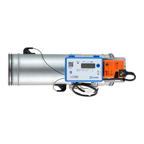
Option A: Connect to premounted cable
Connect the premounted cable in a junction box near the FTCU. Connect
power and signal cables in the junction box according to the color scheme
on the label on the premounted cable, see picture to the right.
When connecting Modbus signal wires, the length of the premounted
cable needs to be as short as possible, since these have a negative effect
on signal quality.
In this case, place junction box as close to the FTCU as possible, then cut
the premounted cable where it is as short as possible for installation.
Connection of
UltraLink
Note! All cables that are
not connected must be
insulated.
24V Red
GND White
+B Yellow
-A Brown
GND Grey
AO1 Green
AO2 Blue
AIN Pink


