- 16 - - 17 -
Lichtfunktion
Modus DIP-
Schalter 2 Tasterkonfi-
guration DIP-
Schalter 4
Status Tasterfunktion
Vollautomatik ON/ON-OFF Beleuchtung ist
ausgeschaltet Beleuchtung wird für die
eingestellte Nachlaufzeit
eingeschaltet.
Vollautomatik ON-OFF Beleuchtung ist
eingeschaltet Die Beleuchtung wird für
die eingestellte Nachlaufzeit
ausgeschaltet und bei
erkannter Bewegung
wird diese nachgetriggert
(Inversbetrieb/Presentation
mode).
Vollautomatik ON Beleuchtung ist
eingeschaltet Die eingestellte Nachlaufzeit
wird neu gestartet.
Halbautomatik ON/ON-OFF Beleuchtung ist
ausgeschaltet Die Beleuchtung wird für
die eingestellte Nachlaufzeit
eingeschaltet.
Halbautomatik ON-OFF Beleuchtung ist
eingeschaltet. Beleuchtung wird bis
zur nächsten Aktivierung
ausgeschaltet.
Halbautomatik ON Beleuchtung ist
eingeschaltet Die eingestellte Nachlaufzeit
wird neu gestartet.
7. Entsorgung
Elektrogeräte, Zubehör und Verpackungen sollen einer umweltgerechten
Wiederverwertung zugeführt werden.
Werfen Sie Elektrogeräte nicht in den Hausmüll!
Nur für EU-Länder:
Gemäß der geltenden Europäischen Richtlinie über Elektro- und Elektronik-
Altgeräte und ihrer Umsetzung in nationales Recht müssen nicht mehr
gebrauchsfähige Elektrogeräte getrennt gesammelt und einer umweltgerechten
Wiederverwertung zugeführt werden.
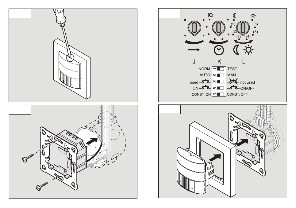
DIP 4 – (ON / ON/OFF ) (Abb. 5.4)
Auf Stellung ON-OFF lässt sich die Beleuchtung jederzeit manuell ein- und aus-
schalten. Auf der Stellung ON ist manuelles Ausschalten nicht mehr möglich.
Bei jedem Tastendruck wird die Nachlaufzeit neu gestartet.
DIP 5 (CONST .ON/CONST. OFF) Konstantlichtregelung (Abb. 5.4)
Die Funktion sorgt für ein gleichbleibendes Helligkeitsniveau. Der Melder misst
das vorhandene Tageslicht und schaltet anteiliges Kunstlicht zu, um das ge-
wünschte Helligkeitsniveau zu erreichen. Ändert sich der Tageslichtanteil, wird
das zugeschaltete Kunstlicht angepasst. Die Zuschaltung erfolgt neben dem
Tageslichtanteil in Abhängigkeit von Anwesenheit.
Taster für Lichtfunktion
Die Funktion des integrierten Tasters (A) ist abhängig von der Konfiguration
des Sensors sowie der aktuellen Betriebssituation. Bei Tastendruck länger als
1 Sekunde wird die Beleuchtung gedimmt.
➜ Tabelle "Lichtfunktion"
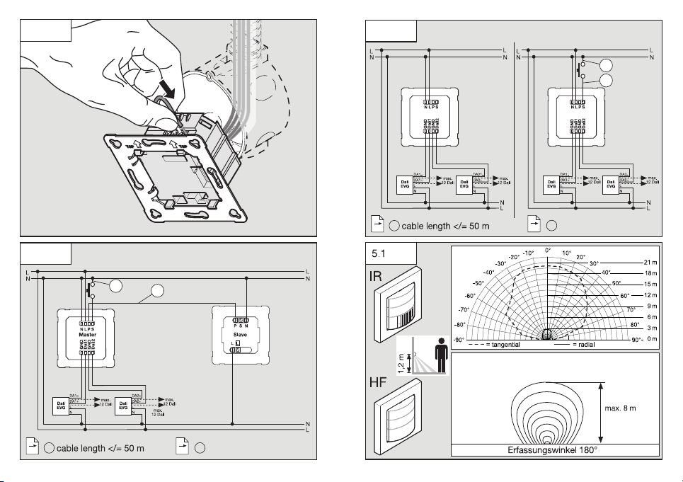
Dämmerungseinstellung
Anwendungsbeispiele Helligkeitssollwerte
Dämmerungsbetrieb min
Flure, Eingangshallen 1
Treppen, Rolltreppen, Fahrbänder 2
Waschräume, Toiletten, Schalträume, Kantinen 3
Verkaufsbereich, Kindergärten, Vorschulräume, Sporthallen 4
Arbeitsbereiche: Büro-, Konferenz-, und Besprechungsräu-
me, feine Montagearbeiten, Küchen 5
Sehintensive Arbeitsbereiche: Labor, technisches Zeichnen,
präzises Arbeiten >=6
Tageslichtbetrieb max
Hinweis: Je nach Montageort kann eine Korrektur der Einstellung erforderlich
sein. Die Helligkeitsmessung erfolgt am Sensor.
Lichtfunktion
Modus DIP-
Schalter 2 Tasterkonfi-
guration DIP-
Schalter 4
Status Tasterfunktion
Vollautomatik ON/ON-OFF Beleuchtung ist
ausgeschaltet Beleuchtung wird für die
eingestellte Nachlaufzeit
eingeschaltet.
Vollautomatik ON-OFF Beleuchtung ist
eingeschaltet Die Beleuchtung wird für
die eingestellte Nachlaufzeit
ausgeschaltet und bei
erkannter Bewegung
wird diese nachgetriggert
(Inversbetrieb/Presentation
mode).
Vollautomatik ON Beleuchtung ist
eingeschaltet Die eingestellte Nachlaufzeit
wird neu gestartet.
Halbautomatik ON/ON-OFF Beleuchtung ist
ausgeschaltet Die Beleuchtung wird für
die eingestellte Nachlaufzeit
eingeschaltet.
Halbautomatik ON-OFF Beleuchtung ist
eingeschaltet. Beleuchtung wird bis
zur nächsten Aktivierung
ausgeschaltet.
Halbautomatik ON Beleuchtung ist
eingeschaltet Die eingestellte Nachlaufzeit
wird neu gestartet.