Steiner ZTM 1250 User manual

WARNING: If incorrectly used this machine can cause severe injury. Those who use
and maintain this machine should be trained in its proper use, warned of its dangers
and should read the entire manual before attempting to set up, operate, adjust or
service the machine.
SETUP, PARTS & MAINTENANCE
MANUAL ZTM 1250
Power Unit Model:
442105-Power Unit ZTM1250 25 Klr Collection
(Operation & Safety Manual: 4136742)
For Cutterdecks:
954204A-Cutterdeck 42” Collection
954804A-Cutterdeck 48” Collection
(Parts Manual: 4136039)
4136743 REV B

CALIFORNIA
Proposition 65 Warning
Diesel engine exhaust and some of
its constituents are known to the State
of California to cause cancer, birth
defects and other reproductive harm.
Californie Proposition 65
Avertissement
Les échappements des moteurs diesel
et certains de leurs composés sont
reconnus par l’Etat de Californie pour
être cancérigènes, provoquer des
défauts congénitaux et d’autres dangers
en matière de reproduction.
ADVERTENCIA
AVERTISSEMENT
WARNING
The engine exhaust from this product
contains chemicals known to the State
of California to cause cancer, birth
defects or other reproductive harm.
California Advertencia
de la Proposicion 65
El estado de California hace saber que
los gases de escape de los motores
diesel y algunos de sus componentes
producen cáncer, defectos de
nacimiento y otros daños en el
proceso de reproducción humana.
L’
é
mission du moteur de ce mat
é
riel
contient des produits chimiques que
l’Etat de Californie consid
è
re
ê
tre
canc
é
rig
è
nes, provoquer des d
é
fauts
cong
é
nitaux et d’autres dangers en
mati
è
re de reproduction.
El estado de California hace saber
que los gases de escape de este
producto contienen productos
quÍmicos que producen cáncer,
defectos de nacimiento y otros daños
en el proceso de reproducción
humana.
CALIFORNIA
Proposition 65 Warning
Battery posts, terminals, wiring
insulation, and related accessories
contain lead and lead compounds,
chemicals known to the State of
California to cause cancer and birth
defects or other reproductive harm.
WASH HANDS AFTER HANDLING.

1
ZTM 1250ZTM 1250
ZTM 1250ZTM 1250
ZTM 1250
12-2005
IMPORTANT MESSAGE
Thank you for purchasing this Steiner product. You have purchased a world class mowing product, one of the
best designed and built anywhere.
This machine comes with an Operation and Safety Manual and a separate Setup, Parts and Maintenance Manual.
The useful life and good service you receive from this machine depends to a large extent on how well you read and
understand these manuals. Treat your machine properly, lubricate and adjust it as instructed, and it will give you
many years of reliable service.
Your safe use of this Steiner product is one of our prime design objectives. Many safety features are built in, but
wealsorelyonyourgoodsenseandcaretoachieveaccident-freeoperation. Forbestprotection,studythemanuals
thoroughly. Learn the proper operation of all controls. Observe all safety precautions. Follow all instructions and
warnings completely. Do not remove or defeat any safety features. Make sure those who operate this machine
are as well informed and careful in its use as you are.
See a Steiner dealer for any service or parts needed. Steiner service ensures that you continue to receive the
best results possible from Steiner’s products. You can trust Steiner replacement parts because they are
manufactured with the same high precision and quality as the original parts.
Steiner designs and builds its equipment to serve many years in a safe and productive manner. For longest life,
use this machine only as directed in the manuals, keep it in good repair and follow safety warnings and instructions.
You'll always be glad you did.
Jacobsen, a Textron Company
One Bob Cat Lane
Johnson Creek, WI 53038-0469
TABLE OF CONTENTS FIGURES PAGE
SAFETY ......................................................................................................................................................... 2
ASSEMBLY AND SETUP ............................................................................................................................ 3-5
MAINTENANCE CHART................................................................................................................................ 6
MAINTENANCE RECORD ............................................................................................................................ 7
MAINTENANCE ........................................................................................................................................ 8-13
ADJUSTMENTS...................................................................................................................................... 14-16
BELT REPLACEMENT............................................................................................................................ 17-20
SPECIFICATIONS .................................................................................................................................. 21-23
ENGINE & FRAME ASSEMBLY ......................... FIGURE 1 ................................................................. 24, 25
WHEELS & BRAKES ......................................... FIGURE 2 ................................................................. 26, 27
FRONT PANEL & PUSH ARMS ......................... FIGURE 3 ................................................................. 28, 29
PUMPS & CONTROL PANEL ............................ FIGURE 4 ................................................................. 30, 31
BLOWER & FUEL TANK.................................... FIGURE 5 ................................................................. 32, 33
BELTS ................................................................ FIGURE 6 ................................................................. 34, 35
BUMPER & GRASSBOX FRAME ...................... FIGURE 7 ................................................................. 36, 37
HEAVY DUTY AIR CLEANER ............................ FIGURE 8 ................................................................. 38, 39
GRASSBOX ....................................................... FIGURE 9 ................................................................. 40, 41
ELECTRICAL ..................................................... FIGURE 10 ............................................................... 42, 43
HYDRAULICS .................................................... FIGURE 11 ................................................................ 44, 45
SEAT ASSEMBLY ............................................. FIGURE 12 ............................................................... 46, 47
DECALS ............................................................. FIGURE 13 ............................................................... 48, 49
OPTIONAL FILL INDICATOR : 970145.............. FIGURE 14 ............................................................... 50, 51
HYDROGEAR PUMP ......................................... FIGURE 15 ............................................................... 52, 53
BRAKE ASSEMBLY ........................................... FIGURE 16 ............................................................... 54, 55

2
ZTM 1250ZTM 1250
ZTM 1250ZTM 1250
ZTM 1250
SAFETY
NOTICE !!!
Unauthorized modifications may present extreme
safety hazards to operators and bystanders and
could also result in product damage.
Jacobsen, a Textron Company strongly warns
against, rejects and disclaims any modifications,
add-on accessories or product alterations that are
not designed, developed, tested and approved by
Jacobsen’sEngineeringDepartment. AnyJacobsen
product that is altered, modified or changed in any
manner not specifically authorized after original
manufacture–includingtheadditionof“after-market”
accessories or component parts not specifically
approved by Jacobsen–will result in the Jacobsen
Warranty being voided.
Anyandallliabilityforpersonalinjuryand/orproperty
damage caused by any unauthorized modifications,
add-on accessories or products not approved by
Jacobsen will be considered the responsibility of
the individual(s) or company designing and/or
making such changes. Jacobsen will vigorously
pursue full indemnification and costs from any party
responsibleforsuchunauthorizedpost-manufacture
modifications and/or accessories should personal
injury and/or property damage result.
This symbol means:
ATTENTION!
BECOME ALERT!
Your safety and the safety of others is involved.
Signal word definitions:
The signal words below are used to identify levels
of hazard seriousness. These words appear in this
manual and on the safety labels attached to
Jacobsen machines. For your safety and the safety
of others, read and follow the information given with
thesesignal wordsand/orthe symbolshownabove.
DANGER indicates an imminently hazardous
situation which, if not avoided, WILL result in death
or serious injury.
WARNINGindicatesapotentiallyhazardoussituation
which, if not avoided, COULD result in death or
serious injury.
CAUTION indicatesa potentiallyhazardoussituation
which,ifnotavoided,MAY resultinminorormoderate
injury. It may also be used to alert against unsafe
practices or property damage.
CAUTION used without the safety alert symbol
indicates a potentially hazardous situation which, if
not avoided, MAY result in property damage
MODEL NUMBER: This number appears on
sales literature, technical manuals and price lists.
SERIAL NUMBER: This number appears only
on your mower. It contains the model number
followed consecutively by the serial number. Use
this number when ordering parts or seeking
warranty information.

3
ZTM 1250ZTM 1250
ZTM 1250ZTM 1250
ZTM 1250
ASSEMBLY AND SETUP
TOOLS REQUIRED FOR ASSEMBLY
– Wrecking bar
– Claw hammer
– Ratchet: 3/8" drive
– Socket:10 mm
– Pliers
– Side Cutter or Jack knife
NOTE: All references below to the "right" or "left" are with respect to an operator at the controls.
1. Open crates and remove packing material.
2. Open hydrostat release (dump) valves Uon the
pumps on the power unit and roll it off the pallet.
3. Remove the height of cut hairpin cotters from the
height of cut posts and lift the cutterdeck carrier
frame CC off the cutterdeck C.
4. Cut the wire tie holding the PTO shaft to the
deck.
Bolt the discharge chute to the rear of the
cutterdeck with (2) M6x16 carriage bolts, (2) M6
nylon locknuts and (2) washers. The head of the
carriage bolt should be inside the chute.
Connect the small spring between the bracket on
the discharge chute and the bracket on the
cutterdeck.

4
ZTM 1250ZTM 1250
ZTM 1250ZTM 1250
ZTM 1250
7. Have a helper lift the cutterdeck carrier frame as
high as it will go. Connect a counterbalance
spring from the carrier frame to the pin on the
tractor.
ASSEMBLY AND SETUP
5. Roll the power unit up to the cutterdeck. Cut the
tie holding the PTO shaft together. Connect
the PTO shaft to the power unit gearbox with the
quick coupler. Line up the splines in the coupler
with those on the gearbox. Pull back on the
outside of the quick coupler to slide it on the
gearbox, then release. Pull back on the shaft to
seat the locking balls in the groove of the gearbox
shaft. When properly installed the PTO shaft
should not pull off the gearbox shaft. Push the
deck close to the power unit. Guide the
discharge chute into the blower inlet
opening.
6. Roll the deck carrier frame to the power unit.
Slide the receiver blocks over the power unit push
arm pins (3/4"-10x1/4"). Secure the carrier frame
with (2) (3/4 ID x1/4") thick washers and a
hairpin cotter, on each side.

5
ZTM 1250ZTM 1250
ZTM 1250ZTM 1250
ZTM 1250
ASSEMBLY AND SETUP
8. Locate the cutterdeck height of cut posts C under
the corresponding bushings of the cutterdeck
carrier frame. Use the handles on the cutterdeck
to lift the deck, guiding the height of cut posts into
their bushings. Secure each with a 3/4”(19mm)
I.D. washer and large hairpin cotter.
9. Set tire pressures down to 14 psi(.98kg/sq cm).
Tires are over inflated for shipping. Close
hydrostat release (dump) valves opened in step
2, finger tight. Do not overtighten.
10. FINAL PREPARATIONS
– Check the engine and hydraulic oil levels. Top up with the correct oil if necessary. Use 10W30 motor oil
for the engine. Use fresh, clean 15W40 or 20W50 motor oil or 15W50 synthetic motor oil for the hydrau-
lic system.
– Remove the battery from the machine.Fill the battery to the bottom of the vent wells with acid and trickle
charge for several hours.
Battery acid is caustic and fumes are explosive and can cause serious injury or death.
Use insulated tools, wear protective glasses or goggles and protective clothing when working with
batteries. Read and obey the battery manufacturer’s instructions.
Be certain the ignition switch is “OFF” and the key has been removed before servicing the battery.
a) Verify battery polarity before connecting or disconnecting the battery cables.
b) When installing the battery, always assemble the RED, positive ( + ) battery cable first
and the ground, BLACK, negative ( - ) cable last.
c) Tighten cables securely to battery terminals and apply a light coat of silicone dielectric
grease to terminals and cable ends to prevent corrosion. Keep terminal covers in place.
– Read Operation and Safety Manual before starting.
– Run engine at full RPM for 5 minutes before engaging blades to allow the engine to be fully lubricated
before load is applied.
– Check the hydrostat neutral adjustment. Neutral is set at the factory but may require readjustment if air
trapped during the initial oil fill has worked out of the system. See adjustments section later in this
manual.
– Do not use the machine without an approved grass collector, the grass discharge chute or mulching
plates correctly fitted.

6
ZTM 1250ZTM 1250
ZTM 1250ZTM 1250
ZTM 1250
MAINTENANCE CHART
ECNANETNIAM
NOITAREPO
neewtebsemitmumixameraslavretniesehT.bojgniognonasiecnanetniaM
.snoitidnocerevesrednunetfoerommrofreP.
snoitarepoecnanetniam
5TSRIF
SRUOH YLIAD
YREVE
52
SRUOH
YREVE
05
SRUOH
YREVE
001
SRUOH
YREVE
002
SRUOH
YREVE
005
SRUOH
ENIGNE
snoitcurtsnidnanoitamrofnilanoitiddaroflaunamenigneehttlusnoC
levelliokcehCX
skaeLrofkcehCX
ekatnIriAnaelC
neercS X
renaelCriAnaelC
renaelcerP X
renaelCriAnaelC
tnemelE X
sniFgnilooCnaelC X
dnaliOegnahC
retliF Xlaunams'rerutcafunamenigneeeS
pag&kcehC
sgulPkrapS X
SCILUARDYH
skaeLrofkcehCX
levelliokcelC X
dnaliOegnahC
retliF XX
ENIHCAM
kcolretnIkcehC
noitarepO X
eriTkcehC
serusserP X
pupoT/kcehC
yrettaB X
stnioPllAetacirbuLX

7
ZTM 1250ZTM 1250
ZTM 1250ZTM 1250
ZTM 1250
NOTES
_______________________________________________________________
____________________________________________________
________________________________________________________________________
_______________________________________________________________
____________________________________________________________
____________________________________________________
________________________________________________________________________
_______________________________________________________________
____________________________________________________________
_______________________________________________________________
____________________________________________________________
____________________________________________________________
MAINTENANCE RECORD
LARENEG ETAD SRH ETAD SRH ETAD SRH ETAD SRH ETAD SRH ETAD SRH
serusserperitkcehC
stniopllaetacirbuL
stlob&stunkcehC
ENIGNE
levelliokcehC
lioegnahC
naelC
tnemelerenaelcria
snifgniloocnaelC
ecalpeR
tnemelerenaelcria
pag&naelC
sgulpkraps
.sretlifhtobdnaliociluardyh,lioenigneecalpernoitarepofosruoh5tsrifretfA:ETON

8
ZTM 1250ZTM 1250
ZTM 1250ZTM 1250
ZTM 1250
MAINTENANCE
CHECK DAILY
Operator Presence Interlock System - Start Operation
For the engine to crank, the parking brake must be on, the PTO (blades) off and traction levers in the
neutral position. Sit in the seat and check, one by one, if the engine will crank with the parking brake off, the
blades on, and either traction lever out of neutral.
Operator Presence Interlock System - Run Operation
The operator must be in the seat for the engine to run with the parking brake off, the traction levers moved out
of the neutral position, or the blades on. To check:
1. Start the engine and run at 1/2 throttle with the operator on the machine but raised off the seat.
2. One by one: move the parking brake to the “OFF” position, traction levers out of the neutral position (check
each independently), and turn the blades on. Each check should kill the engine after 1/2 second. (A 1/2
second delay is built into the system to prevent engine cutout when in rough terrain.)
Repair machine before using if the Operator Presence Interlock System does not operate correctly in start or
run. Contact your authorized Steiner dealer.
Hardware
Tighten any nuts and bolts found loose. Replace any broken or missing cotter pins. Repair any other
problems before operating.
Tire pressure
Tires should be kept inflated at 14 lbs/in2(1.0 kg/cm2). Improper tire inflation can cause rapid tire wear and
poor traction. Uneven inflation can cause uneven cutting.
Gearboxes
Check for evidence of leaks daily. If leaks are detected, get them repaired immediately to avoid wrecking a
gearbox from lack of lubrication. The gearboxes only contain a few ounces of lubricant, which won’t last long if
there is a leak.
Battery
Battery acid is caustic and fumes
are explosive and can cause serious injury or death.
Use insulated tools, wear protective glasses or
goggles and protective clothing when working with
batteries. Read and obey the battery manufacturer’s
instructions.
Be certain the ignition switch is “OFF” and the key
has been removed before servicing the battery.
1. Verify battery polarity before connecting or
disconnecting the battery cables.
2. When installing the battery, always assemble the
RED, positive ( + ) battery cable first and the
ground, BLACK, negative ( - ) cable last.
3. When removing the battery, always remove the
ground, negative ( - ) cable first and the red,
positive ( + ) cable last.
4. Check the electrolyte level every 100 hours of
operation.
5. Clean the cable ends and battery posts with
steel wool. Use a solution of baking soda and
water to clean the battery. Do not allow the
solution to enter into the battery cells.
6. Tighten cables securely to battery terminals and
apply a light coat of silicone dielectric grease to
terminals and cable ends to prevent corrosion.
Keep terminal covers in place.

9
ZTM 1250ZTM 1250
ZTM 1250ZTM 1250
ZTM 1250
MAINTENANCE
LUBRICATION
Every 50 hours of operation, lubricate the following points with grease:
1. Caster wheel pivots (2 points)
2. Caster wheel bearings ( 2 points)
3. Deck pivot (2 points, every 100 hrs.)
4. Pusharm (2 points, every 100 hrs.)
5. Deck idler pivot (1 point)
6. Drive shaft slip sleeve (1point)
7. Drive shaft u-joints (2 points)
8. Rear caster pivot (1 point)
9. Rear caster bearing (1 point)
NOTE ON BLADE SPINDLES -The blade spindles and blower spindle
(if so equipped) on these machines use a superior sealed bearing that does
not require relubrication.

10
ZTM 1250ZTM 1250
ZTM 1250ZTM 1250
ZTM 1250
MAINTENANCE
HYDRAULIC SYSTEM
Check fluid level in the hydraulic system every 100
hours or when a leak has occurred. If the fluid is
low, check all components for leaks.
To check, remove reservoir cap M. The fluid level
should be at the bottom of the filler tube. If low, top up
(do not overfill). Use one of the oils listed below:
– SAE 15W40 motor oil
– SAE 20W50 motor oil
– 15W50 synthetic motor oil
AFTER FIRST FIVE (5) HOURS
1. Remove plug Nto drain hydraulic reservoir.
Dispose of used oil in accordance with local
requirements.
2. Clean and replace the plug.
3. Change hydraulic oil filter G.
4. Fill the reservoir with fresh oil to the bottom of the
reservoir filler tube, using an oil from the list
above. Do not overfill.
PERIODIC OIL CHANGES
Change the hydraulic fluid and hydraulic filter after
each 500 hours of operation using the same
procedure given above.
NOTES:
Before servicing the hydraulic system, stop the engine, disconnect spark plug wires and disengage the PTO.
– After any hydraulic line is opened, plug or cap it promptly to reduce the risk of contamination.
– Do not use teflon tape on hydraulic pipe fittings. Use a liquid sealant that will dissolve into the system.
– Make sure all hydraulic connections are tight and hydraulic hoses and lines are in good condition before
applying pressure to system.
The machine's hydraulic system operates under high pressure. When checking for leaks, do not use your
hands to attempt to find a leak. Instead, use cardboard or paper. Escaping hydraulic fluid can be under
sufficient pressure to penetrate skin and cause serious injury. If hydraulic fluid is injected into the skin, it
must be promptly removed by a doctor familiar with this form of injury or gangrene may result.
View from right side

11
ZTM 1250ZTM 1250
ZTM 1250ZTM 1250
ZTM 1250
SPARK PLUGS
Remove each plug and check condition.
– Good operating conditions are indicated if the plug has a light coating of grey or tan deposit.
– A white blistered coating indicates overheating. A black coating indicates an “over rich” fuel mixture.
Both may be caused by a clogged air cleaner or improper carburetor adjustment.
– Do not sandblast, wire brush or otherwise attempt to repair a plug in poor condition. Best results are
obtained with a new plug.
– Set plug gap as specified in engine manual..
MAINTENANCE
ENGINE OIL
Do not perform engine maintenance without the
engine off, spark plug wires disconnected and PTO
disengaged.
AFTER FIRST FIVE (5) HOURS
While the engine is warm:
1. Remove drain cap Dand drain the crankcase.
Dispose of used oil in accordance with local
requirements.
2. Clean and replace the cap.
3. Change oil filter.
4. Fill the crankcase with fresh oil to the full mark.
Do not overfill. See engine manual for oil
specifications.
DAILY
1. Check oil level with the dipstick.
2. If oil is needed, add fresh oil of proper viscosity
and grade. See engine manual for oil
specifications. Do not overfill.
3. Replace dipstick before starting engine.
PERIODIC OIL CHANGES
1. See engine manual for oil and filter change
intervals after the break-in period.
2. Follow instructions for first oil change, above.
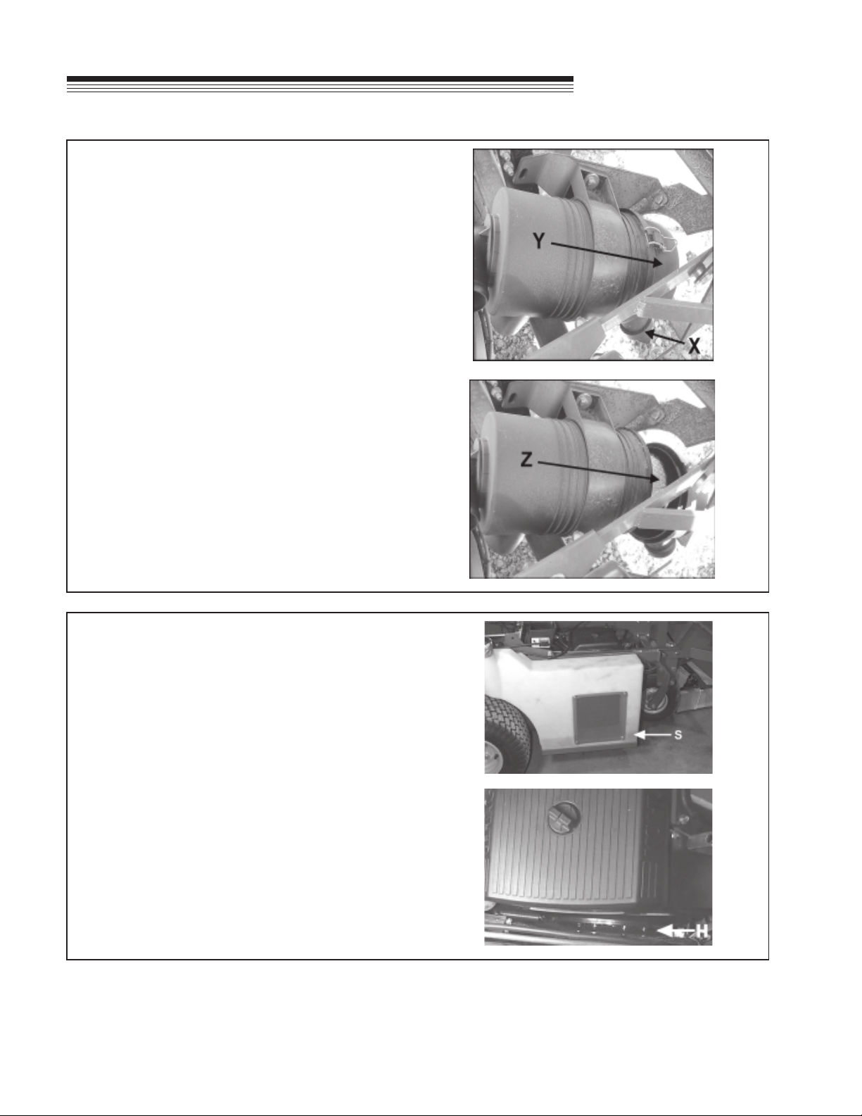
FUEL FILTER
An inline fuel filter Sis located at the right side of the
engine. Inspect at every oil change to make sure it
is clean and unobstructed. Replace if dirty.
12
ZTM 1250ZTM 1250
ZTM 1250ZTM 1250
ZTM 1250
ENGINE COOLING
Continued operation with a clogged cooling system
will cause severe overheating and can result in
engine damage.
–Daily: Clean air intake screen S.
–Every 100 hours: Clean cooling fins beneath
blower housing Hwith reference to information in
the engine manufacturer's manual.
MAINTENANCE
AIR CLEANER
The air cleaner with this engine has a high density
paper air cleaner cartridge. It should be inspected
regularly and maintained. Uneven running, lack of
power or black exhaust fumes may indicate a dirty air
cleaner.
To clean or replace diesel engine air cleaner element:
1. Unclamp end cover Yand remove element Z.
2. Insert new element and replace end cover by
clamping in position as shown on the cover.
Every 100 hours (more often under very dusty or dirty
conditions), check the paper cartridge.
– Clean by tapping gently.
– Do not wash the cartridge or use compressed air
which can cause damage.
– Replace when cartridge is dirty, bent or damaged.

13
ZTM 1250ZTM 1250
ZTM 1250ZTM 1250
ZTM 1250
BLADE REMOVAL
Follow these instructions to prevent injury during
blade removal:
1. Loosen with a box wrench or a socket and long
breaker bar. To gain additional leverage, slip a
long pipe or thick-walled tube over breaker bar or
wrench.
2. Insert a block of wood A as shown to prevent
blade from turning when loosening.
3. Wear thickly padded gloves. Keep hands clear of
blade path. Blades may rotate when bolt
releases.
SHARPENING
Blades may be sharpened by filing or grinding.
–Inspect blades before sharpening.
–Replace bent or cracked blades.
–Replace blades when the lift portion has worn
thin.
–Maintain cut angle at 30o.
–Do not overheat blades when sharpening.
–Always use Steiner blades. Use of another
manufacturer’s blades may be dangerous.
BLADE BALANCE
Blade balance must be maintained at 5/8 oz-in (19.4
g-cm) or less. Failure to keep blades balanced
causes excess vibration, wear, and shortened life of
most components of the machine.
To balance a blade:
1. Sharpen blade first.
2. Balance the blade at the center.
3. Attach a 1/8 oz (3.9 g) weight at a distance 5"
(127 mm) from center on the light end. This
should make the light end the heavy end:
– If it does, the blade is balanced.
– If does not, file or grind the heavy end until
the addition of the weight makes the light end
the heavy end.
BLADE INSTALLATION
1. Wear thickly padded gloves to prevent cuts from
the sharp blade.
2. Insert the blade bolt, in order, through the conical
washer (cup side toward the blade, as shown),
the blade, and the blade spacer.
3. Install assembly on the blade spindle.
4. Torque the blade bolt to 70 ft-lbs.
MAINTENANCE

14
ZTM 1250ZTM 1250
ZTM 1250ZTM 1250
ZTM 1250
ADJUSTMENTS
HEIGHT OF CUT
The height of cut is set by raising or lowering the
cutterdeck on the carrier frame.
To change the height of cut:
1. Hold the deck up with the handle H provided.
2. Remove the hairpin cotters on one side.
3. Raise or lower the deck to the desired height of
cut P.
Secure the height of cut with the hairpin
cotters.
4. Repeat for the other side.
NOTES:
- Large changes in the height of cut may need to
be done in two steps-1/2 in the first step, 1/2 in the
second step.
- Height of cut may vary due to the amount of tread
on the tires, variances in tire diameter, and
inflation pressure.
BELTS
All V-belts are tensioned by spring loaded idlers. No adjustment is required. The blade drive timing belt
does not require adjustment once properly tensioned.

15
ZTM 1250ZTM 1250
ZTM 1250ZTM 1250
ZTM 1250
ADJUSTMENTS
PARKING BRAKE
Adjust the parking brake to provide 1/4” travel in each
cable before the slack is taken up.
To adjust:
1. Start with the brake in the 'OFF' position.
2. Remove the pin Pholding the brake links to the
brake cable ends.
3. Reinstall the pin but only through the end of one
cable.
4. Move the brake lever toward the 'ON' position
until the slack in the cable is taken up, and
resistance
from the brake spring begins to be felt.
5. Adjust the cable with jam nuts Jso there is
1/4”(6mm) of slack before the resistance of the
spring is felt.
6. Repeat for the other brake cable. When both
cables have been adjusted, reinstall the brake pin
through both cable ends and secure with the
hairpin cotter.
NOTE: If there isn’t enough adjustment at the brake
lever end of the cables, the drive wheels may be
removed and the cable adjusted at the mounting
bracket. Further adjustment may be obtained by
turning the bracket over.
Parking brake assembly - (brake in ON position).
Parking brake assembly - (brake in OFF position).

16
ZTM 1250ZTM 1250
ZTM 1250ZTM 1250
ZTM 1250
ADJUSTMENTS
HYDROSTAT ADJUSTMENTS
A turnbuckle-style hydrostat neutral adjustment is
provided.
Neutral:
1. Support the machine with the drive wheels off the
ground. Use jackstands or equivalent support.
Do not rely only on mechanical or hydraulic jacks.
2. Move the traction levers into the neutral position
and raise the seat and grass collection hopper or
utility box.
3. Disconnect the seat switch and temporarily connect
the two terminals with jumper wire Jas shown.
4. Loosen jam nuts T( (h) =hidden) at both ends of
the turnbuckle.
5. Start the engine and run at low speed.
6. Hold one of the traction control levers up against
the resistance of the reverse return spring. Rotate
the corresponding turnbuckle until the wheel it
controls turns in reverse, then rotate the turnbuckle
in the opposite direction until the wheel stops
turning. Lock the turnbuckle jam nuts. Run the
engine up to high idle and stroke the pump in
forward and reverse to check the adjustment.
Re-adjust if necessary.
7. Repeat steps 4 through 6 for the opposite side.
8. Remove the jumper wire and reconnect the seat
switch. Lower the grass collection hopper or utility
box
Reverse Return:
1. Move traction levers to neutral and raise the seat.
2. Locknuts Ushould be run on the bolt as far as they
will go.
3. Loosen jam nuts Y. Move the traction levers to
their forward stop. Adjust the clevis yoke by turning
the head of the bolt until the pin through the clevis
yoke is up against the back end of the slot in the
traction control shaft lever. Once the initial setting
is made for both sides, the levers may be evened
up by adjusting the how far the bolt is turned into
the clevis. Tighten jam nut Y.
NOTE: A slight creep in reverse is acceptable provided
the wheel does not turn and the hydrostat pump does
not whine when the parking brake is on. The reverse
return should be adjusted and set before neutral is set
on the hydrostatic transmissions.

17
ZTM 1250ZTM 1250
ZTM 1250ZTM 1250
ZTM 1250
NOTE: Always use Steiner replacement belts, not general purpose belts. Steiner belts are specially
designed for use on commercial mowers and will normally last longer.
BELT REPLACEMENT
ENGINE-CUTTERDECK (PTO) BELT
1. Raise the seat and grass collection hopper or
utility box.
2. Disconnect the electric clutch from the wire
harness at plug P.
3. Remove the carriage bolts securing torque
restraint Qto the clutch.
4. Insert the square drive end of a 3/8” ratchet or
breaker bar into the square hole in the idler arm
and use the ratchet handle to rotate the idler
assembly enough to remove the belt from the
idler and gearbox pulley.
5. Work the belt out of the space between the
gearbox pulley and the frame and remove it from
the electric clutch pulley.
6. Install the new belt by doing steps 1 through 4 in
reverse order.

18
ZTM 1250ZTM 1250
ZTM 1250ZTM 1250
ZTM 1250
GEARBOX-BLOWER BELT
1. Raise the grass collection hopper.
2. Insert a 3/8" rachet in the square hole on the
Gearbox-Blower idler arm. Use it to rotate the
arm enough to remove the belt from the
gearbox pulley. Remove the E-ring securing the
idler arm at the pivot and slide the idler arm out
far enough to remove the belt.
3. Install the new belt by performing steps 1 & 2 in
reverse order.
BELT REPLACEMENT
ENGINE-PUMP BELT
1. Remove the Engine-Gearbox belt. See
Engine Gearbox belt in the preceding section.
2. Use a 9/16" wrench on the bolt Bsecuring the
idler pulley to rotate the idler arm enough to
remove the belt from the idler and pump pulleys.
Finish removing the belt from the engine pulley.
3. Install the new belt by doing steps 1 and 2 in
reverse order.
PUMP-PUMP BELT
1. Raise the seat and grass collection hopper or
utility box.
2. Remove the Engine-Pump belt from the pump
only. The Engine-Gearbox belt does not need to
be removed. See Engine-Pump belt in the
preceeding section.
3. Rotate the Pump-Pump idler arm enough to
remove the belt from the idler and pump pulleys.
A 3/8" breaker bar may be useful to rotate the
idler arm.
4. Install the new belt by doing steps 1 and 2 in
reverse order.
This manual suits for next models
1
Table of contents


