Subaru SGX3500 User manual

SGX3500
SGX5000
SGX7500

3- 3 -
CONTENTS
Section Title
Page
1. SPECIFICATIONS..........................................................1
2. PERFORMANCE CURVES.....................................................2
3. GENERAL DESCRIPTION......................................................4
4. RANGE OF APPLICATIONS...................................................7
5. MEASURING PROCEDURES..................................................14
5-1 MEASURING INSTRUMENTS.................................................14
5-2 AC OUTPUT MEASURING...................................................16
5-3 MEASURING INSULATION RESISTANCE..........................................16
6. CHECKING FUNCTIONAL MEMBERS.............................................18
6-1 RECEPTACLES..........................................................18
6-2 CIRCUIT BREAKER........................................................18
6-3 STATOR. .............................................................19
6-4 ROTOR ASSEMBLY. ......................................................19
6-5 BRUSH. ..............................................................20
6-6 A.V.R. (AUTOMATIC VOLTAGE REGULATOR). ......................................21
6-7 OIL SENSOR . ..........................................................22
7. DISASSEMBLY AND ASSEMBLY ............................................... 23
7-1 PREPARATION and PRECAUTIONS.............................................23
7-2 DISASSEMBLY PROCEDURES.................................................23
7-3 COMPONENT PARTS......................................................27
7-4 ASSEMBLY PROCEDURES...................................................32
7-5 CHECKING, DISASSEMBLY and REASSEMBLY of the CONTROL PANEL......................39
8. TROUBLESHOOTING. ......................................................40
8-1 NO AC OUTPUT..........................................................40
8-2 AC VOLTAGE IS TOO HIGH OR TOO LOW.........................................41
8-3 AC VOLTAGE IS NORMAL AT NO-LOAD, BUT THE LOAD CANNOT BE APPLIED...............42
9. WIRING DIAGRAM .......................................................43
NOTE
This Service Manual excludes information for engine.
As for the total servicing information as a generator set, please refer in conjunction with the
Subaru EX series OHC Engine Service Manual.

SGXSpecificationsheet
ModelSGX3500 SGX5000 SGX7500E
EmissionCompliancy 49state 49state 49state
CSACompliant Yes Yes Yes
Type BrushType BrushType BrushType
VoltageRegulation AVRAVR AVR
Frequency 60HZ/Single 60HZ/Single60HZ/Single
Voltage 120/240 120/240 120/240
MaxOutput(watts) 3500 4900 7300
MaxAmps 29.2/14.6 40.8/20.4 60.8/30.4
RatedOutput(watts) 3200 4500 6700
RatedAmps 26.6/13.3 37.5/18.8 55.8/27.9
dba@ratedoutput(7meters) 72 76 76
CurrentProtection
Dualpolemagneticcircuit
breaker&GFCI
Dualpolethermalmagnetic
circuitbreakers&GFCI
Dualpolethermalmagnetic
circuitbreakers&GFCI
ModelEX217HP EX3010HP EX4014HP
Type SubaruOHC SubaruOHC SubaruOHC
LowOilSystem LowOilShutdown LowOilShutdown LowOilShutdown
FuelTankCapacity 4gallons 7gallons 8gallons
ContinuousOperation:
Hoursatratedload 8hours 9.4hours 7hours
Hoursatrated1/2load 10.7hours 12.7hours 10.3hours
StartingSystem RecoilRecoilElectricw/Recoilbackup
BatteryIncluded‐Battery
replacementorequal N/A N/A 12V.18AH(nut&bolttype)
InterstateBSL1116
Dimensions(LxWxH) 27"x25"x25" 31"x28"x27" 34"x28"x27"
DryWeight(includeswheelkit) 122lbs.154lbs.212lbs.
GFCI120V,20Aduplex 1 2 2
120V.20ATwistlock 1 1 N/A
120/240V.20ATwistlock 1 1 N/A
120V.30ATwistlock N/A N/A 1
120/240V,30ATwistlock N/A N/A 1
Hourmeter * * *
WheelKit * * *
OilSAE30W1Quart * * *
Note:
**DimensionsandDryWeightincludebatteryandwheelkit,lessextendedhandles
*Fueltankcapacitymeasuredata20%inclineisasfollows:
SGX3500‐2.9gal.,SGX5000‐5.25gal.,SGX7500E‐5.94gal.

- 2 -
2. PERFORMANCE CURVES
SGX5000
60Hz-240V
0
5
10
15
20
25
30
35
40
45
50
55
60
65
70
75
80
85
90
95
100
0 2 4 6 8 10121416182022
Current (A)
0
500
1000
1500
2000
2500
3000
3500
4000
4500
5000
O utp ut (VA)
Voltage (v)
Frequency (Hz)
Output (VA)
240
250
Voltage (V) Frequency (Hz)
245
235
SGX3500
60Hz-240V
0
5
10
15
20
25
30
35
40
45
50
55
60
65
70
75
80
0 2 4 6 8 10 12 14 16
Current (A)
0
500
1000
1500
2000
2500
3000
3500
4000
O utput (VA)
Voltage (v)
Frequency (Hz)
Output (VA)
Voltage (V) Frequency (Hz)
240
250
245

- 3 -
SGX7500
60Hz-240V
0
5
10
15
20
25
30
35
40
45
50
55
60
65
70
75
0 5 10 15 20 25 30 35
Current (A)
0
500
1000
1500
2000
2500
3000
3500
4000
4500
5000
5500
6000
6500
7000
7500
Output (VA)
Voltage (v)
Frequency (Hz)
Output (VA)
240
Voltage (V) Frequency (Hz)
235
230

- 4 -
3. GENERAL DESCRIPTION

- 5 -
CONTROL PANEL

- 6 -
SERIAL NUMBER
Serial number is stamped on the label stuck on the fuel tank.
NOTE : Always specify serial number when inquiring about the generator or ordering spare parts
in order to get correct parts and accurate service.
CONSTRUCTION
EARTH TERMINAL
BRUSH HOLDER
AVR UNIT
END COVER STATOR BOLT
REAR COVER FRONT COVER
PRO D No. / SER No.( Labe l)

- 7 -
4. RANGE OF APPLICATIONS
Generally, the power rating of an electrical appliance indicates the amount of work that can be
done by it. The electric power required for operating an electrical appliance is not always equal to
the output wattage of the appliance. The electrical appliances generally have a label showing their
rated voltage, frequency, and power consumption (input wattage). The power consumption of an
electrical appliance is the power necessary for using it. When using a generator for operating an
electrical appliance, the power factor and starting wattage must be taken into consideration.
In order to determine the right size generator, it is necessary to add the total wattage of all
appliances to be connected to the unit.
Refer to the followings to calculate the power consumption of each appliance or equipment by its
type.
(1) Incandescent lamp, heater, etc. with a power factor of 1.0
Total power consumption must be equal to or less than the rated output of the generator.
Example : A rated 3000W generator can turn thirty 100W incandescent lamps on.
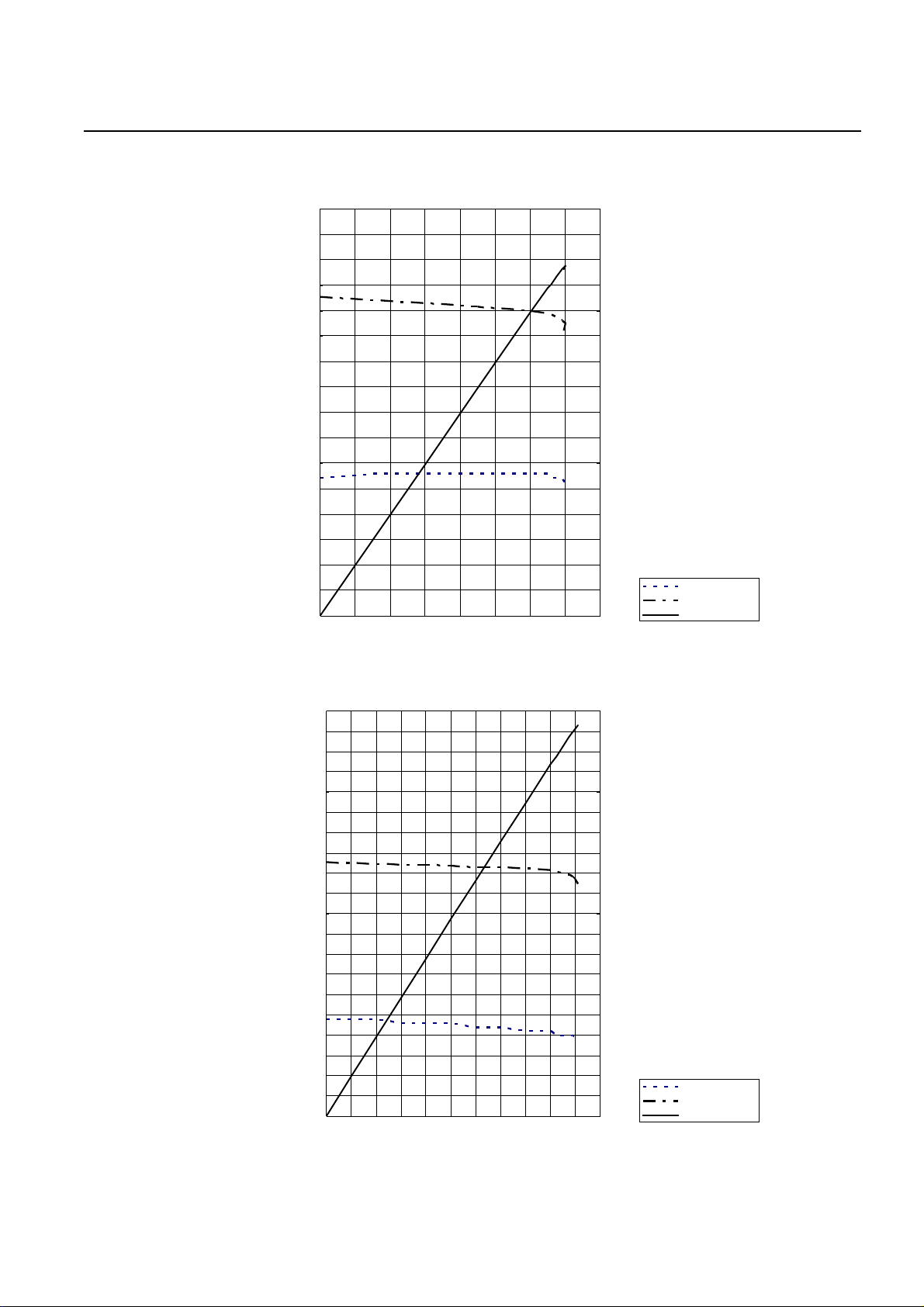
(2) Fluorescent lamps, motor driven tools, light electrical appliances, etc. .
with a smaller power factor
Select a generator with a rated output equivalent to 1.2 to 2 times of the power consumption of
the load. Generally the starting wattage of motor driven tools and light electrical appliances are
1.2 to 3 times lager than their running wattage.
Example: A rated 250 W electric drill requires a 400 W generator to start it.
NOTE 1: If a power factor correction capacitor is not applied to the fluorescent lamp, the more
power shall be required to drive the lamps.
NOTE 2: Nominal wattage of the fluorscent lamp generally indicates the output wattage of the lamp.
Therefore, if the fluorescent lamp has no special indication as to the power consumption,
efficiency should be taken into account as explained in ltem (5) on the following page.
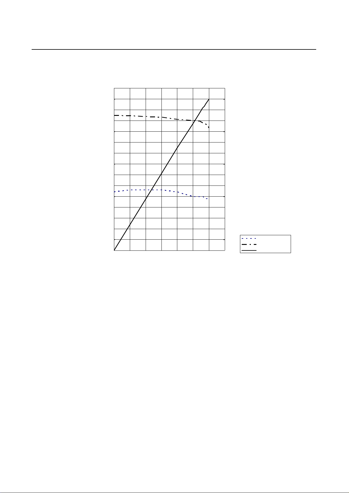
(3) Mercury lamps with a smaller power factor
Loads for mercury lamps require 2 to 3 times the indicated wattage during start-up.
Example : A 400 W mercury lamp requires 800 W to 1200 W power source to be turned on. A
rated 3000 W generator can power two or three 400 W mercury lamps.
(4) Initially loaded motor driven appliances such as water pumps, compressors, etc.
These appliances require large starting wattage which is 3 to 5 times of running wattage.
Example : A rated 900 W compressor requires a 4500 W generator to drive it.
NOTE 1: Motor-driven appliances require the aforementioned generator output only at the
starting. Once their motors are started, the appliances consume about 1.2 to 2 times
their rated power consumption so that the excess power generated by the generator
can be used for other electrical appliances.
NOTE 2 : Motor-driven appliances mentioned in items (3) and (4) vary in their required motor
starting power depending on the kind of motor and start-up load. If it is difficult to
determine the optimum generator capacity, select a generator with a larger capacity.

- 8 -
(5) Appliances without any indication as to power consumption
Some appliances have no indication as to power consumption; but instead the work load
(output) is indicated. In such a case, power consumption is to be worked out according to the
numerical formula mentioned below.
(Output of electrical appliance) = (Power consumption)
(Efficiency)
Efficiencies of some electrical appliances are as follows :
Single-phase motor . . . . . 0.6 to 0.75 The smaller the motor, the
Fluorescent lamp . . . . . . 0.7 to 0.8 Lower the efficiency.
Example 1 : A 40W fluorescent lamp means that its luminous output is 40W. Its efficiency is 0.7
and accordingly, power consumption will be 40÷0.7= 57W. As explained in Item (2),
multiply this power consumption value of 57 W by 1.2 to 2 and you will get the figure
of the necessary capacity of a generator. In other words, a generator with a rated
output of 1000W capacity can light nine to fourteen 40 W fluorescent lamps.
Example 2 : Generally speaking, a 400 W motor means that its work load is 400 W. Efficiency of
this motor is 0.7 and power consumption will be 400÷0.7= 570 W. When this motor is
used for a motor-driven tool, the capacity of the generator should be multiple of 570
W by 1.2 to 3 as explained in the ltem (3). 570 (W) × 1.2 to 3 = 684 (W) to 1710 (W)
SGX3500 SGX5000 SGX7500
Incandescent lamp, Heater 3200 4500 6700
Fluorescent lamp, Electric tool 1750 2500 3700
Mercury lamp 1250 1800 2650
Pump, Compressor 800 1100 1650
Applicable Wattage(approx. W)
Applications
Table.4-1

- 9 -
NOTES : Wiring between generator and electrical appliances
1. Allowable current of cable
Use a cable with an allowable current that is higher than the rated input current of the load
(electrical appliance). If the input current is higher than the allowable current of the cable
used, the cable will become excessively heated and deteriorate the insulation, possibly
burning it out. Table 4-2 shows cables and their allowable currents for your reference.
2. Cable length
If a long cable is used, a voltage drop occurs due to the increased resistance in the
conductors decreasing the input voltage to the load (electrical product). As a result, the load
can be damaged. Table 4-2 shows voltage drops per 100 meters of cable.
R means resistance (Ω/100 m) on the above table.
I means electric current through the wire (A).
L means the length of the wire (m).
The length of wire indicates round length, it means twice the length from generator to
electrical tools.
mm2 No. A No./mm Ω/100m 1A 3A 5A 8A 10A 12A 15A
0.75 18 7 30/0.18 2.477 2.5V 7.5V 12.5V - - - -
1.25 16 12 50/0.16 1.486 1.5V 4.5V 7.5V 12V 15V 18V -
2.0 14 17 37/0.26 0.952 1V 3V 5V 8V 10V 12V 15V
3.5 12 to 10 23 45/0.32 0.517 - 1.5V 2.5V 4V 5V 6.5V 7.5V
5.5 10 to 8 35 70/0.32 0.332 - 1V 2V 2.5V 3.5V 4V 5V
Voltage drop
Table.4-2
No.of strands
/ strands dia. Resistance Current Amp.
Nominal
cross
section
A.W.G. Allowable
current

- 10 -
(6) AC Receptacle
AC receptacles are used for taking AC output power from the generator.
The rated current for each receptacle is shown as follows;
CAUTION
Be careful not to use the receptacles
beyond the specified amperage limits to
prevent circuit breaker trinpping.
CAUTION
To connect the appliance the l ocking
type rceptacle, insert the plug in to the
receptacle and then turn it clockwise to
l ock.

- 11 -
Check the amperage of the receptacles used referring to table.4-3, and be sure not to take a
current exceeding the specified amperage.
Be sure that the total wattage of all appliances does not exceed the rated output of the generator.
Table. 4-3
NOTE :
When the AC circuit breaker turns off during operation, the generator is over
loaded or the appliance is defective. Stop the generator immediately, check
the appliance and / or generator for overloading or detect and have repaired as
necessary by Subaru Industrial Power Products dealer or service shop.

- 12 -
GFCI RECEPTACLE
After starting the engine, check the GFCI for proper functioning by the following test procedure.
・Push the TEST button, The RESET button will pop out exposing the word TRIP. Power is now
off at the outlets protected by the GFCI, indicating that the device is functioning properly.
・If TRIP dose not appear when testing, do not use the generator. Call a qualified electrician.
・To restore power, push RESET button.
CONNECTING TO DOMESTIC CIRCUIT (HOUSE WIRING)
(a) When connecting a Subaru generator to a house wiring, generator output power must be taken
from the 240V-4P receptacle.
(b) Install a transfer switch.
A transfer switch must be installed to transfer the load from the commercial power source
to the generator. This switch is necessary to prevent accidents caused by the recovery from
power outage. Use a transfer switch of the correct capacity.
Install transfer switch between the meter and the fuse or AC breaker box.
If the RESET button pops out during operation, stop the generator
immediately and call a qualified electrician for checking generator and
appliances.
This generator is neutral bonded type.
If a generator is to be connected to residential or commercial power
lines, such as a stand by power source during power outage, a ll
connections must be by a licensed electrician.
Failure in connection may result in dea th, personal injury ,damage to
generator, damage to appliances, damage to the building's wiring or fire.
IF the neutral wire of house wiring is grounded, be sure to ground the
ground terminal of the generator, Otherwise an electric shock may occur
to the operator.
[CAUTION]

- 13 -

- 14 -
5. MEASURING PROCEDURES
5-1 MEASURING INSTRUMENTS
(1) VOLTMETER
AC voltmeter is necessary.
The approximate AC voltage ranges of the
voltmeters to be used for various types of
generators are as follows :
0 to 150 V : Type with an output voltage of
110 or 120 V
0 to 300 V : Type with an output voltage of
220, 230 or 240 V
0 to 150 V, 0 to 330 V : Dual voltage type
(2) AMMETER
AC ammeter is necessary.
An AC ammeter with a range that can be
changed according to the current rating of
a given generator is most desirable.
(About 10 A, 20 A, 100 A)
(3) FREQUENCY METER
Frequency range : About 45 to 65Hz
NOTE : Be careful of the frequency meter's
input voltage range.

- 15 -
(4) CIRCUIT TESTER
Used for measuring resistance, etc.
(5) MEGGER TESTER
Used for measuring generator insulation
resistance.
Select one with testing voltage range of
500V.
(6) TACHOMETER
Use the contactless type tacho meter.

- 16 -
5-2 AC OUTPUT MEASURING
Use a circuit above for measuring AC output.
A hot plate or lamp with a power factor of 1.0
may be used as a load. Adjust the load and rpm.
and check that the voltage range is as specified
in the following table at the rated amperage and
rated rpm.
5-3 MEASURING INSULATION RESISTANCE
Use a megger tester to check the insulation
resistance. Remove the control panel, and
disconnect the connector of GREEN lead for
ground. Connect a megger tester to one of
receptacle output terminals and the ground
terminal, then measure the insulation resistance.
Rated voltage
240V-60Hz
SGX3500 239-249
SGX5000 239-249
SGX7500 239-249
Voltage range
model

- 17 -
An insulation resistance of 1 megohm or more is normal.
(The original insulation resistance at the time of shipment from the factory is 10 megohm or more.)
If it is less than 1 megohm, disassemble the generator and measure the insulation resistance of
the stator, rotor and control panel individually.
(1) STATOR
Measure the insulation resistance between
each lead wire and the core.
(2) ROTOR
Measure the insulation resistance between
the slip ring and the core.
(3) CONTROL PANEL
Measure the insulation resistance between
the live parts and the grounded parts.
Any part where the insulation resistance is less than 1MΩ has faulty insulation, and may cause
electric leakage and electric shock.
Replace the faulty part.

- 18 -
6. CHECKING FUNCTIONAL MEMBERS
6-1 RECEPTACLES
Using a circuit tester, check continuity between
the two terminals at the rear of the receptacles
while the receptacle is mounted on the control
panel.
When continuity is found between the output
terminals of the receptacle with a wire connected
across these terminals, the receptacle is normal.
When the wire is removed and no continuity is
found between these terminals, the receptacles
are also normal.
6-2 CIRCUIT BREAKER
Check continuity between each of two
terminals at the rear of the circuit breaker
while it is mounted on the control panel.
Normally, there is continuity between each of
the two when the circuit breaker is on while
there is no continuity when the circuit breaker
is off.
CIRCUIT TESTER
(Continuity test)
PUSH Type LEVER Type
AC CIRCUI BREAKER (Type 1)
AC CIRCUI BREAKER (Type 2)
Max voltageAC CIRCUIT BREAKER Frequency Rated output
SGX5000
SGX7500
60Hz
SGX3500 3200VA
6700VA
4500VA
Rated fault current
18.75A
25A
37.5A
250V
250V
250V
SGX7500 6700VA 125V 20A60Hz
Rated fault currentAC CIRCUIT BREAKER Frequency Rated output Rated voltage
Other manuals for SGX3500
3
This manual suits for next models
3
Table of contents
Other Subaru Portable Generator manuals

Subaru
Subaru RGX2900 User manual

Subaru
Subaru RGX2900 User manual

Subaru
Subaru RGX4800 User manual

Subaru
Subaru RGX2900 User manual

Subaru
Subaru R1100 User manual

Subaru
Subaru RGX3000 User manual

Subaru
Subaru ROBIN RGD3300H User manual

Subaru
Subaru WORMS LEADER 10500 XL21 User manual

Subaru
Subaru RGX6500/E User manual

Subaru
Subaru RGV12100 User manual