Steinlen LA 63 User manual

Edition
5/2022
LA/LE/LES Motors
BA 2330


LA/LE/LES motors for mounting on
MOTOX gearbox
BA 2330
Operating Instructions
Translation of the original instructions
03/2021
A5E37460917A /RS
-AF-ST
General information and
safety notes
1
Technical description
2
Incoming goods, transport,
and storage
3
Installation
4
Commissioning
5
Operation
6
Faults, causes and
remedies
7
Service and maintenance
8
Disposal
9
Technical data
10
Spare parts
11
Explanations
12

Steinlen Elektromaschinenbau GmbH
Ehlbeek 21
30938 BURGWEDEL
GERMANY
A5E37460917A/RS
-
AFST
03/2021 Subject to change
Copyright ©
03/2021
Steinlen Elektromaschinenbau GmbH
Legal information
Warning notice system
This manual contains notices you have to observe in order to ensure your personal safety, as well as to prevent
damage to property. The notices referring to your personal safety are highlighted in the manual by a safety alert
symbol, notices referring only to property damage have no safety alert symbol. These notices shown below are
graded according to the degree of danger.
DANGER
indicates that death or severe personal injury will result if proper precautions are not taken.
WARNING
indicates that death or severe personal injury may result if proper precautions are not taken.
CAUTION
indicates that minor personal injury can result if proper precautions are not taken.
NOTICE
indicates that property damage can result if proper precautions are not taken.
If more than one degree of danger is present, the warning notice representing the highest degree of danger will
be used. A notice warning of injury to persons with a safety alert symbol may also include a warning relating to
property damage.
Qualified Personnel
The product/system described in this documentation may be operated only by personnel qualified for the specific
task in accordance with the relevant documentation, in particular its warning notices and safety instructions.
Qualified personnel are those who, based on their training and experience, are capable of identifying risks and
avoiding potential hazards when working with these products/systems.
Proper use of Steinlen products
Note the following:
WARNING
Steinlenproducts may only be used for the applications described in the catalog and in the relevant technical
documentation. If products and components from other manufacturers are used, these must be recommended
or approved by Steinlen. Proper transport, storage, installation, assembly, commissioning, operation and
maintenance are required to ensure that the products operate safely and without any problems. The permissible
ambient conditions must be complied with. The information in the relevant documentation must be observed.
Trademarks
All names identified by ® are registered trademarks of Steinlen Elektromaschinenbau GmbH. The remaining
trademarks in this publication may be trademarks whose use by third parties for their own purposes
could violate the rights of the owner.
Disclaimer of Liability
We have reviewed the contents of this publication to ensure consistency with the hardware and software
described. Since variance cannot be precluded entirely, we cannot guarantee full consistency. However, the
information in this publication is reviewed regularly and any necessary corrections are included in subsequent
editions.
Ⓟ
All rights reserved

BA 2330
Operating Instructions, 03/2021, A5E37460917A/RSAFST 3
Table of contents
1 General information and safety notes ...............................................................................................7
1.1 General information.........................................................................................................7
1.2 Copyright ........................................................................................................................9
1.3 Use as prescribed.............................................................................................................9
1.4 Installation notes ...........................................................................................................10
1.5 Geared motor with encoder for safety-relevant applications ..............................................11
1.6 Obligations of the user...................................................................................................12
1.7 The five safety rules .......................................................................................................13
1.8 Particular types of hazards ..............................................................................................13
2 Technical description ......................................................................................................................15
2.1 General technical description ..........................................................................................15
2.2 Cooling .........................................................................................................................16
2.3 Backstop at the motor ....................................................................................................16
2.4 Terminal box and application box....................................................................................17
2.5 SINAMICS G110M frequency inverters .............................................................................17
2.6 Rating plate ...................................................................................................................18
2.7 Surface treatment..........................................................................................................18
2.7.1 General information on surface treatment .......................................................................18
2.7.2 Painted version ..............................................................................................................19
2.7.3 Primed version...............................................................................................................21
3 Incoming goods, transport, and storage..........................................................................................23
3.1 Incoming goods .............................................................................................................23
3.2 Transport ......................................................................................................................24
3.2.1 General information on transport....................................................................................24
3.2.2 Fastening for suspended transport ..................................................................................25
3.3 Storage .........................................................................................................................26
4 Installation......................................................................................................................................27
4.1 Unpacking.....................................................................................................................27
4.2 General information on installation .................................................................................27
4.3 Thread sizes and tightening torques for fastening bolts.....................................................28
4.4 Installation conditions for the motor................................................................................29
4.5 Condensation drain hole (optional) .................................................................................29
4.6 Connecting the motor in the terminal box .......................................................................30

Table of c ontents
4
4.6.1 General information on motor connection .......................................................................30
4.6.2 Terminal box .................................................................................................................31
4.6.3 Terminal marking ..........................................................................................................32
4.6.4 Direction of rotation ......................................................................................................33
4.6.5 Connecting the cables in the terminal box ....................................................................... 34
4.6.6 External grounding ........................................................................................................34
4.6.7 Installation and routing.................................................................................................. 35
4.6.8 External fan (optional) ...................................................................................................37
4.7 Operation on the converter ............................................................................................40
5 Commissioning...............................................................................................................................41
5.1 Checking the insulation resistance.................................................................................. 41
5.2 Commissioning the motor .............................................................................................. 43
6 Operation .......................................................................................................................................45
7 Faults, causes and rem edies ...........................................................................................................47
8 Servic e and m ainten ance................................................................................................................ 49
8.1 General notes about maintenance ..................................................................................49
8.2 Locking the manual release of the brake (optional) ..........................................................49
8.3 Lubrication....................................................................................................................50
8.4 Cleaning the motor........................................................................................................52
8.5 Checking the tightness of fastening bolts ........................................................................52
8.6 Inspection of the motor .................................................................................................. 53
8.7 Servicing the brake ........................................................................................................53
8.7.1 Wear of the spring-operated brake ..................................................................................53
8.7.2 Maintenance intervals for the brake ................................................................................55
8.7.3 Adjusting the air gap...................................................................................................... 56
8.7.4 Replacin g the friction lin ing ............................................................................................ 58
9 Disposal..........................................................................................................................................61
10 Technical data ................................................................................................................................ 63
10.1 Type designation ...........................................................................................................63
10.2 Rating plate data ........................................................................................................... 64
10.2.1 General technical data ...................................................................................................64
10.2.2 Rating plate MOTOX geared motors ....................................................................... 64
10.3 Weight ..........................................................................................................................66
10.4 Circuit diagrams ............................................................................................................ 66
11 Spare parts .....................................................................................................................................
69
11.1 Stocking of spare parts...................................................................................................69
11.2Lists of spare parts......................................................................................................... 70
BA 2330
Operating Instructions, 03/2021, A5E37460917A/RSAFST
11.2.1 Motor sizes 63 - 250.......................................................................................................70
11.2.2 Brake ............................................................................................................................75
11.2.3 Backstop .......................................................................................................................78
11.2.4 Encoder on fan cover .....................................................................................................79

Table of contents
5
11.2.5 Encoder in the motor with external fan............................................................................80
11.2.6 SINAMICS G110M frequency inverters .............................................................................
81
12 Explanations ......................................................................................................................................83
BA 2330
Operating Instructions, 03/2021, A5E37460917A/RSAFST
12.1 EU-Declaration of Conformity.................................................................................................83
12.2EU-Declaration of Conformity DIN EN 80079-36 ...................................................................85
12.3UK Declaration of Conformity BS EN 80079-36 .................................................................... 86

Table of c ontents
6
BA 2330
Operating Instructions, 03/2021, A5E37460917A/RSAFST

7
General information and safety notes
1
1.1 General information
Note
Steinlen Elektromaschinenbau GmbH does not accept any liability for damage and failures
that result from the nonobservance of these operating instructions.
Note
European RoHS directive
MOTOX geared motors comply with the stipulations laid down in Directive 2011/65/EU
regarding restrictions in theuse of certain hazardous substances.
These operating instructions are part of the motor delivery. Store the operating instructions
near the motor. Please read theoperating instructions prior to handling the motor and
observe the information they contain. This is the best way of ensuringsafe and disturbance-
free operation.
These operating instructions apply to the standardversion of the motors for mounting on the
MOTOX gearbox series:
•LA motor, sizes 63 to 71
•LE motor, sizes 63 to 160
•LES motor, sizes 180 to 250
For a description of the precise designation, see Type designation (Page 63).
Table 1- 1 Article number code
Motor
Article number position
1
2
3
4
11
12
LA motor with standard efficiency
S
T
3
3
1
1
LE motor with standard efficiency
2
1
LE motor with high efficiency
2
2
LE motor with premium efficiency
2
3
LES motor with standard efficiency
3
1
LES motor with high efficiency
3
2
LES motor with premium efficiency
3
3
BA 2330
Operating Instructions, 03/2021, A5E37460917A/RSAFST

General information and safety notes
1.1 General information
8
The latest versions of the operating instructions, the declaration of incorporation and the
declarations of conformity are available in electronic form in the Industry Online Support
(https://www.steinlen.eu).
Valid operating instructions for MOTOX
●BA 2010 - operating instructions for MOTOX gearboxes
●BA 2011 - operating instructions for MOTOX worm gearbox SC
●BA 2012 - operating instructions for MOTOX worm gearbox S
●BA 2019 - operating instructions for MOTOX input units
●BA 2310 - operating instructions for three-phase and single-phase AC motors and motors
equipped with brake with accessories
●BA 2320 - operating instructions for LA/LG and LAI/LGI motors
●BA 2330 - operating instructions for LA/LE/LES motors
●BA 2510 - operating instructions for MOTOX optional add-on units
●BA 2515 - operating instructions for MOTOX gearboxes for overhead conveyors
BA 2330
Operating Instructions, 03/2021, A5E37460917A/RSAFST

General information and safety notes
1.2 Copyright
9
1.2 Copyright
The copyright to these operating instructions is held by Steinlen Elektromaschinenbau GmbH.
These operating instructions must not be wholly or partly reproduced for competitive
purposes, used in an y unau thorized way or made available to third parties without
agreement of Steinlen Elektromaschinenbau GmbH .
1.3 Use as prescribed
The motors described in these operating instructions have been designed for stationary use in
general engineering applications.
They comply with the harmonized standards of the series EN 60034 ( VDE 0530) . They are not
approved for operation in hazardous zones and areas.
Unless otherwise agreed, the motors have been designed for use in plant s and equipm en t i n
industrial environm ent s.
The motors have been built using stateoftheart technology and are shipped in an
operation ally reliable condit io n . C h an ges made by u sers cou ld affect t h is operat ion al
reliability an d are forbidden .
Note
The data on th e rating plate assumesan installation altitu de of up to 1000 m above sea level.
The permissible ambient temperature is stamped on the rating plate.
In the case of other ambient temperatures and installation altitudes, contact Technical
Support.
BA 2330
Operating Instructions, 03/2021, A5E37460917A/RSAFST

General information and safety notes
1.4 Installation notes
10
The motors have been designed for theapplication described in Section Technical data
(Page 63). Do not operate the motor outside thespecified power limit. Other operating
conditions must be contractually agreed.
Never use degrees of protection ≤IP54 outdoors. Air-cooled versions are designed for
ambient temperatures of -20 °C to +40 °C as standard and for an installation altitude of up to
1 000 m above sea level. Please note any deviations to the data on the rating plate.
Conditions at the location of use must comply with all specifications on the rating plate.
Do not climb on the motor. Do not place any objects on the motor.
1.4 Installation notes
Prerequisites for smooth, vibration-free running
•Stable foundation design
•Precise alignment of the machine
•Correct balancing of theparts to be mounted on theshaft extension
•Compliance with vibration severity values according to ISO 20816-1
Vibration severity
Due to the influencing variables listed below, the vibration response of thesystem atthe
location of usecan lead to increased vibration severity on the drive unit:
•Transmission elements
•Installation conditions
•Alignment and installation
•Effects of external and internal oscillation
The vibration severity values specified in accordance with ISO 20816-1 must not be exceeded
at any point on the surface of the drive. This ensures problem-free operation and a long
service life.
Maximum permissible vibration severity
Observe the values for the maximum permissible radial and axial oscillation vibration severity
in the following table. Radial/axial refers to the motor axes.
Vibration frequency
Vibration value
< 6.3 Hz
Vibration displacements≤0.16 mm
6.3 Hz to 250 Hz
Vibration velocity vrms ≤4.5 mm/s
> 250 Hz
Vibration acceleration apeak ≤10 m/s
2
BA 2330
Operating Instructions, 03/2021, A5E37460917A/RSAFST

General information and safety notes
1.5 Geared motor with encoder for safety-relevant applications
11
Maximum permissible axial vibration severity
Vibration velocity
Vibration acceleration
Vibration velocity vrms ≤4.5 mm/s
Vibration acceleration apeak ≤10 m/s
2
Resonant frequencies
Resonance can occur in the speed range of the geared motor depending on the machine to
be driven.
Operation in resonancecauses increased noise and vibration levels.
Adherence to the maximum permissible vibration severity is always required.
Operation in the resonant frequency leads to a reduced service life of the geared motor,
irrespective of adherence to the maximum vibration severity.
Continuous operation in the resonant frequency must be avoided.
1.5 Geared motor with encoder for safety-relevant applications
For a MOTOX geared motor with encoder for safety-relevant applications, it is crucial that
you observe the operating instructions BA 2730.These operating instructions arevalid for the
functionally safe encoders that are mounted ontoMOTOX geared motors. The functionally
safe encoders are in compliance with the relevant standards for safety-relevant applications
listed in the declaration of conformity of BA 2730.
The SMOTOX geared motor with functionally safe encoder has a signal yellow marking on
the fan cover. Marking SI04 for thefunctionally safe encoder is stamped on the rating plate.
The safety level is marked on the functionally safe encoder.
Figure 1-1 Marking for functional safety
BA 2330
Operating Instructions, 03/2021, A5E37460917A/RSAFST

General information and safety notes
1.6 Obligations of the user
12
1.6 Obligations of the user
The company operating the unit must ensure thatall persons assigned to work on the geared
motor have read and understood these operating instructions and that they comply with
them in all points in order to:
•Eliminate the risk to life and limb of users and others
•Ensurethe operational safety of the geared motor.
•Avoid disruptions and environmental damage through incorrect use.
Comply with the following safety instructions:
Shut down the geared motors and disconnect the power before you carry out any work on
them.
Make sure that the drive unit cannot be turned on accidentally, e.g. lock the key-operated
switch. Place a warning notice at the drive connection point which clearly indicates that work
is in progress on the geared motor.
Carry out all work with great care and with due regard to "safety".
For all work, carefully comply with the relevant regulations for work safety and
environmental protection.
Comply with the instructions on the rating plates attached to the geared motor. The rating
plates must be kept free from paint and dirt at all times. Replace any missing rating plates.
In the event of changes during operation, switch off the drive unit immediately.
Take appropriate protective measures to prevent accidental contact with rotating drive parts,
such as couplings, gear wheels or belt drives.
Take appropriate protective measures to prevent accidental contact with parts and
equipment that heat up to over +70 °C during operation.
When removing protective equipment, keep fasteners in a safe place. Re-attach removed
protective equipment before commissioning.
Collect and dispose of used oil in accordance with regulations. Immediately remove any spilt
oil with an oil-binding agent.
Do not carry out any welding work on the geared motor. Do not usethe geared motor as a
grounding point for welding operations.
Carry out equipotential bonding in accordance with applicable regulations and directives by
electrotechnology specialists.
Do not use high-pressure cleaning equipment or sharp-edged tools to clean the geared
motor.
Comply with the permissible tightening torque of the fastening bolts.
BA 2330
Operating Instructions, 03/2021, A5E37460917A/RSAFST

General information and safety notes
1.7 The five safety rules
13
Replace damaged bolts with new bolts of thesame type and strength class.
Steinlen Elektromaschinenbau GmbH accepts the warrant y only for original spare parts.
The manufacturerwho installs the geared motors in a plant must include the regulations
contained in the operating instructions in its own operating instructions.
Make surethat you observe themaximum permissible vibration levels specified in
ISO 20816-1 (zone limit A) during operation.
1.7 The five safety rules
For your own personal safety and to prevent material damage when carrying out any work,
always observe the safety-relevant instructions and the following five safety rules according
to EN 50110-1 Working in a voltage-free state. Apply the five safety rules in the sequence
statedbefore startingwork.
Five safety rules
1. Disconnect.
Also disconnect the auxiliary circuits, for example the anti-condensation heating.
2. Secureagainst reconnection.
3. Verify absence of operating voltage.
4. Ground andshort circuit.
5. Cover or safeguardneighboring live parts.
After the work has been completed, undo the measures taken in the reverse order.
1.8 Particulartypes of hazards
WARNING
Extreme surface temperatures
Hot surfaces over +55 °C pose a burn risk.
Cold surfaces below 0 °C pose a risk of damage due to freezing.
Do not touch the gearbox without protection.
BA 2330
Operating Instructions, 03/2021, A5E37460917A/RSAFST

General information and safety notes
1.8 Particular types of hazards
14
WARNING
Hot, escaping oil
Before starting any work wait until the oil has cooled down to below +30 °C.
WARNING
Poisonous vapors when working with solvents
Avoid breathing in vapors when working with solvents.
Ensure adequate ventilation.
WARNING
Risk of explosion when working with solvents
Ensure adequate ventilation.
Do not smoke!
WARNING
Risk of eye injury
Rotating parts can throw off small foreign particles such as sand or dust.
Wear protective eyewear!
In addition to theprescribed personal protection gear, also wear suitable protective gloves
and safety glasses.
BA 2330
Operating Instructions, 03/2021, A5E37460917A/RSAFST

15
Technical description
2
2.1 General technical description
The motor complies with the following regulations:
Table 2- 1 Overview of the standards
Topic
Standard
Dimensions and operation characteristics
EN 60034-1
Degree of protection
EN 60034-5
Cooling
EN 60034-6
Mounting position according to modular system
EN 60034-7
Terminal marking and direction of rotation
EN 60034-8
Noise emission
EN 60034-9
Thermal protection
EN 60034-11
Starting characteristics for rotating electrical motors
EN 60034-12
Vibration severity levels
EN 60034-14
IEC standard voltages
IEC 60038
Safety of machinery
EN 60204-1
The motor is equipped with grease-lubricated roller bearings. The bearings are permanently
lubricated.
The stator winding is designed for temperature class 155 (F).The stator winding can be
optionally implemented with temperature class 180 (H).
In thestandard version, therotor corresponds to vibration severity level A.
The technical data for the optional monitoring equipment can be viewed in thecircuit
diagrams, on the rating plate or in the special order documents.
The stator housing and bearing shields are made of die-cast aluminum or cast iron.
The surface of the stator housing is equipped with cooling fins and a mounted terminal box
or motor connector.
BA 2330
Operating Instructions, 03/2021, A5E37460917A/RSAFST

Technical description
2.2 Cooling
16
2.2 Cooling
NOTICE
Dust deposits prevent heat radiation
Dust deposits prevent heat radiation and cause a high housing temperature.
Keep the motor free from dirt, dust etc.
The motor is designed to be cooled by means of fins. An external fan draws in the cooling air
through the aperture in the fan cover and blows the air over the surfaceof thestator
housing.
2.3 Backstop at the motor
NOTICE
Service life limited
Drive speeds below 1 000 rpm or frequent startingand stopping operations
(≥20 starts / stops per hour) will limit service life.
Ensurethat the backstop is replaced in time when frequent startingand stopping operations
are performed.
NOTICE
Damage or destruction due to incorrect direction of rotation
Do not runthe motor against the backstop.
Note the directional arrow on the motor.
Note
The backstop is not suitable for ambient temperaturesunder -25 °C.
The motor can be fitted with a mechanical backstop. The backstop permits only the correct
direction of rotation during operation. The motor is marked by an arrow pointing in the
corresponding direction.
The backstop is fitted with centrifugally operated sprags. When the motor is running in the
specified direction, the inner ring and the cage with the sprags also rotate while the outer
ring remains stationary.
BA 2330
Operating Instructions, 03/2021, A5E37460917A/RSAFST

Technical description
2.4 Terminal box and application box
17
If the drive speed exceeds the speed listed in the table, the sprag rises. The backstop is wear-
free. The backstop does not require any maintenance.
Table 2- 2 Minimum drive speed when using backstops
Motor size Backstop
Speed
rpm
71
FXM31-17DX
> 890
80
FXM31-17DX
> 890
90, 100, 112
FXM38-17DX
> 860
132
FXM61-19DX
> 750
160
FXM66-25DX
> 730
180, 200
FXM76-25DX
> 670
225, 250
FXM86-25DX
> 630
2.4 Terminal box and application box
The following are contained in the motor terminal box:
•Terminals for the motor (terminal board)
•Terminals for checking equipment
•Terminals for anti-condensation heating
•Connector for the brake
The number of available terminals is shown in the circuit diagrams. The circuit diagrams are
located in the terminal box.
2.5 SINAMICS G110M frequency inverters
Note
SINAMICS G110M inverters are not suitable for ambient temperatures below -10 °C.
The user documentation for the inverters integrated in the motor will be supplied separately.
BA 2330
Operating Instructions, 03/2021, A5E37460917A/RSAFST

Technical description
2.6 Rating plate
18
Resetting the parameters to their factory settings
Resetting the parameters to their factory settings means that the motor parameter values
deviate from the required values. Restore the relevant motor parameter values.
Procedure
1. Set the value of parameter p0010 to 30.
2. Set the value of parameter p0970 to 10.
Detailed information can be found in the G110M List Manual.
2.6 Rating plate
The rating plate on the gearbox or geared motor is of coated aluminum foil. The rating plate
is glued using a special masking film. The film ensures permanent resistance to UV radiation
and media of all kinds, such asoils, greases, salt water and cleaning agents.
The adhesive and the material ensurefirm adhesion and long-term legibility within the
operating temperature range from -40 °C to +155 °C.
The edges of the rating plate are paint-finished to match the color of the gearbox or motor to
which it is affixed.
2.7 Surface treatment
2.7.1 General information on surface treatment
All paint finishes are sprayed on.
NOTICE
Failure of the external protection
If the paint finish is damaged, the geared motor may corrode.
Do not damage the paint finish.
Note
Information about the ability to be repainted does not guarantee the quality of the paint
product supplied by your supplier.
Only the paint manufacturer is liable for the quality and compatibility.
BA 2330
Operating Instructions, 03/2021, A5E37460917A/RSAFST
This manual suits for next models
13
Table of contents
Popular Engine manuals by other brands
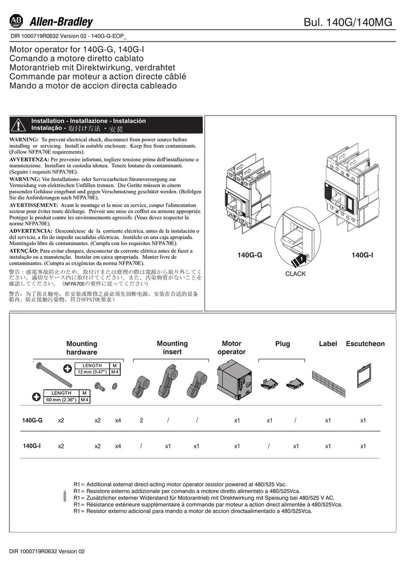
Allen-Bradley
Allen-Bradley 140G Series Installation
Rockwell Automation
Rockwell Automation Allen-Bradley TLP-SSN-F046 installation instructions

Seidel
Seidel UMS ST 7-70 instruction manual

Siemens
Siemens 1PH818 Operating instructions & installation instructions
Teryair
Teryair 2VMS Series Operation and maintenance guide

Black Bruin
Black Bruin BB series General Instructions for Use
