Nexen AIR CHAMP FMCBE 70-14 User manual

FORM NO. L-20365-B-0714
1
FMCBE Model 70-14
Metric Face Mounted Enclosed
Clutch Brake With/Without Integral
Valve
AIR CHAMP PRODUCTS
FORM NO. L-20365-B-0714

2
FORM NO. L-20365-B-0714
Copyright 2014 Nexen Group, Inc.
Nexen Group, Inc.
560 Oak Grove Parkway
Vadnais Heights, Minnesota 55127
ISO 9001 Certified
This document is the original, non-translated, version.
Conformity Declaration: In accordance with Appendix II B of CE Machinery Directive (2006/42/EC):
A Declaration of Incorporation of Partly Completed Machinery evaluation for the applicable EU directives was
carried out for this product in accordance with the Machinery Directive. The declaration of incorporation is set
out in writing in a separate document and can be requested if required.
This machinery is incomplete and must not be put into service until the machinery into which it is to be
incorporated has been declared in conformity with the applicable provisions of the Directive.
Read this manual carefully before installation and operation.
Follow Nexen’s instructions and integrate this unit into your
system with care. This unit should be installed, operated and
maintained by qualified personnel ONLY. Improper installation
can damage your system, cause injury or death. Comply with
all applicable codes.
DANGER
In accordance with Nexen’s established policy of constant product improvement, the specifications contained in this manual
are subject to change without notice. Technical data listed in this manual are based on the latest information available at
the time of printing and are also subject to change without notice.
Technical Support: 800-843-7445
(651) 484-5900
www.nexengroup.com

FORM NO. L-20365-B-0714
3
Table of Contents
General Specifications -------------------------------------------------------------------------------------------------------------------------- 4
General Safety Precautions ------------------------------------------------------------------------------------------------------------------- 4
Installation ------------------------------------------------------------------------------------------------------------------------------------------------- 5
Lubrication ------------------------------------------------------------------------------------------------------------------------------------------- 6
Air Connections ----------------------------------------------------------------------------------------------------------------------------------- 7
Air and Electrical Connections (Integral Valve Style) --------------------------------------------------------------------------------------- 8
FMCBE Model 70-14 Assembly (NPT Style) ----------------------------------------------------------------------------------------------- 9
FMCBE Assembly ----------------------------------------------------------------------------------------------------------------------------------- 10
Troubleshooting --------------------------------------------------------------------------------------------------------------------------------------- 12
Replacement Parts ----------------------------------------------------------------------------------------------------------------------------- 13
Warranty -------------------------------------------------------------------------------------------------------------------------------------------- 15

4
FORM NO. L-20365-B-0714
GENERAL SPECIFICATIONS
GENERAL SAFETY PRECAUTIONS
CAUTION
Use lifting aids and proper lifting
techniques when installing, removing,
or placing this product in service.
CAUTION
Watch for sharp features when
interacting with this product. The parts
have complex shapes and machined
edges.
Specifications
Max Static Torque Clutch: 10 Nm (7.4 ft-lbs)
Brake: 10 Nm (7.4 ft-lbs)
Actuation Pressure .1 - 5.5 bar (1 - 80 psi)
Service Temperature 4.5 - 104 C (40 - 220 F)
Approximate Weight Up to 6.5 kg (14.5 lbs)
CAUTION
Use appropriate guarding for moving
components. Failure to guard could
result in serious bodily injury.
WARNING
Ensure proper guarding of the product is
used. Nexen recommends the machine builder
design guarding in compliance with OSHA 29
CFR 1910 “Occupational Safety and Health
Hazards”.
WARNING
This product is capable of emitting
a spark if misused, therefore it is not
recommended for use in any explosive
environment.
CAUTION
The temperature limits for the product
are 4.5-104 degree Celsius (40-220
degree F).
CAUTION
The temperature limits for the
product are 4.5-104 degree
Celsius (40-220 degree F).
CAUTION
Use appropriate guarding for moving
components. Failure to guard could
result in serious bodily injury.

FORM NO. L-20365-B-0714
5
MOUNTED ON THE SHAFT END OF A MOTOR
Refer to Figure 1.
1. Remove the Socket Head Cap Screws (Item 13) and
the Housing (Item 1).
2. Insert the Customer Supplied Key into the motor shaft
keyway.
3. Slide the Housing (Item 1) onto the motor shaft, then
secure it to the motor with the Socket Head Cap
Screws (Item 29).
4. Align the Set Screw (Item 26) in the Drive Disc (not
shown) with the hole in the Housing (Item 1).
5. Tighten the Set Screw (Item 26) and install the Plug
(Item 27). Align the FMCBE Model 70-14 air inlet ports
to the 6 o’clock down position to allow condensation
to drain out of the ports.
MOUNTED BETWEEN A GEAR REDUCER AND A
MOTOR
Refer to Figure 2.
1. Remove the Socket Head Cap Screws (Item 13) and
the Housing (Item 1).
2. Insert the Customer Supplied Key into the motor shaft
keyway.
3. Slide the Housing (Item 1) onto the motor shaft, then
secure it to the motor with the Socket Head Cap
Screws (Item 29).
4. Align the hole in the Housing (Item 1) with the Set
Screw (Item 26) in the Drive Disc.
5. Tighten the Set Screw (Item 26) and install the Plug
(Item 27). See “NOTICE”.
6. Apply a drop of Loctite® 242 to the threads of the four
Socket Head Cap Screws (Item 13) and secure the
two halves of the FMCBE Model 70-14 together.
7. Tighten the four Socket Head Cap Screws (Item 13)
to 6.1-7.5 Nm (54-66 in/lbs).
FIGURE 1
Item 26
Item 27
Item 1
Customer
Supplied
Key
Motor
Item 29
Item 13
FIGURE 2
Item 26
Item 27
Item 1
Motor
Item 29
Item 13
Customer
Supplied
Fasteners
Gear
Reducer
Customer
Supplied
Key
Item 25
INSTALLATION
6. Apply a drop of Loctite® 242 to the threads of the four
Socket Head Cap Screws (Item 13) and secure the
two halves of the FMCBE Model 70-14 (Metric Face
Mounted Enclosed Clutch Brake) together.
7. Tighten the four Socket Head Cap Screws (Item 13)
to 6.1-7.5 Nm (54-66 in/lbs).
8. Insert the Key (Item 25) into the Stub Shaft (not shown).
9. Slide the Stub Shaft into the Gear Reducer.
10. Secure the FMCBE Model 70-14 to the Gear Reducer
with the customer supplied fasteners.

6
FORM NO. L-20365-B-0714
NOTE
Nexen pneumatically actuated devices require clean, pressure regulated air for maximum performance and life.
All seals in Nexen Pneumatically operated devices are lubricated for life and do not require additional lubrication.
However, some customers prefer to use an air line lubricator, which injects oil into the pressurized air, forcing an
oil mist into the air chamber. This is acceptable, but care must be taken to ensure once an air mist lubrication
system is used, it is continually used over the life of the product as the oil mist may wash free the factory
installed lubrication.
Locate the lubricator above and within ten feet of the product, and use low viscosity oil such as SAE-10.
Synthetic lubricants are not recommended.
Nexen product's bearings are shielded and pre-lubricated, and require no further lubrication.
LUBRICATOR DRIP RATE SETTINGS
1. Close and disconnect the air line from the unit.
2. Turn the Lubricator Adjustment Knob counterclockwise
three complete turns.
3. Open the air line.
LUBRICATION
CAUTION
These settings are for Nexen supplied
lubricators. If you are not using a Nexen
lubricator, calibration must follow the
manufacturer's suggested procedure.
4. Close the air line to the unit when a drop of oil forms
in the Lubricator Sight Gage.
5. Connect the air line to the unit.
6. Turn the Lubricator Adjustment Knob clockwise until
closed.
7. Turn the Lubricator Adjustment Knob counterclockwise
one-third turn.
8. Open the air line to the unit.

FORM NO. L-20365-B-0714
7
3/2 (3 Way) 4/2 (4 Way)
5/2 (4 Way) 5/2 (5 Way)
AIR CONNECTIONS
NOTE
For quick response, Nexen recommends a quick exhaust
valve and short air lines between the Control Valves and
the product. Align the air inlet ports to a down position
to allow condensation to drain out of the air chambers of
the product.
CAUTION
Low air pressure will cause slippage and
overheating. Excessive air pressure will
cause abrupt starts and stops, reducing
product life.
All Nexen pneumatically actuated devices require clean
and dry air, which meet or exceeds ISO 8573.1:2001
Class 4.4.3 quality.
Air Pressure (Gage) Limits
6.9 Bar (100 PSI) Absolute Max.
0 Bar (0 PSI) Absolute Min.
The following are common air supply schemes used with
this product. These are examples and not an all-inclusive
list. All air circuits to be used with this product must be
designed following EN983 guidelines.

8
FORM NO. L-20365-B-0714
Item 40 Item 13
Item 36
FIGURE 3
Refer to Table 1 and Figures 3 and 4.
1. Connect the air supply to the inlet port.
2. Place the gasket on the Solenoid Valve (Item 36).
NOTE: If you do not install the gasket, you may not get
a proper seal. An improper seal can cause corrosion
in a moist environment.
3. Plug the DIN Connector (Item 40) into the Solenoid
Valve (Item 36).
4. Tighten the pan head screw included on the DIN
Connector (Item 40).
5. Connect the lead wires of the DIN Connector (Item 40)
to an appropriate power source (See Table 1). Observe
polarity when you connect any device marked “+” and
“-”.
Lead Wire Cable:
Brown wire = positive
White wire = common
Green wire = ground
NOTE: The 115 VDC rectified lead wire contains a full
bridge rectifier and surge suppressor which converts
AC power to rectified AC power and provides circuit
protection.
*
A Nexen rectifier lead wire is supplied for the 115 VDC
Ta ble 1 - Spool Specifications
Current
Voltage ResistancePower
and can be used for AC (50/60 Hz) or DC operation.
Standard Coil:
115 VDC
*
2.5 Watts 5500 Ohms .021 Amps
Optional Coils
(Contact Nexen)
24 VDC 0.6 Watts 1100 Ohms .027 Amps
Solenoid
Part #
4919
4961
DIN Connector; 9mm Centers
FIGURE 4
12
Gasket
Solenoid
(Item 36)
DIN
Connector
(Item 40)
Pan Head Screw
Dynamco
DANGER
Hazardous voltages. Can cause severe
injury or death. Disconnect AC power
prior to connecting wires. Do not splice
wires. Conform to all applicable safety
regulations and codes.
AIR AND ELECTRICAL CONNECTIONS (INTEGRAL VALVE STYLE)

FORM NO. L-20365-B-0714
9
FIGURE 5
Housing
Plug
Friction Facing
Splined Disc
Assembly
Cylinder Air
Chamber
O-Ring
Seals
Air to
Brake
Air to
Clutch
Piston
Bearing
Key
Stub
Shaft
Drive
Disc
FMCBE MODEL 70-14 ASSEMBLY (NPT STYLE)

10
FORM NO. L-20365-B-0714
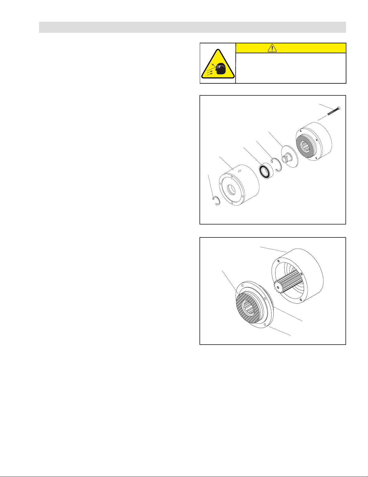
Refer to Figures 6, 7, 8, 9 and 10.
1. Remove the four Socket Head Cap Screws (Item 13)
and slide the Housing (Item 1) Bearing (Item 2), and
the Drive Disc (Item 4) out of the FMCBE.
2. Remove the Retaining Ring (Item 6).
3. Press the Drive Disc (Item 4) out of the Bearing (Item
2) and the Housing (Item 1).
4. Remove the Retaining Ring (Item 3) from the Housing
(Item 1).
5. Support the Housing (Item 1) and press the old Bearing
(Item 2) out of the Housing.
NOTE: Removing the bearing damages it. Do not reuse
the bearing.
6. Clean the bearing bore of the Housing (Item 1) with
fresh safety solvent. Make sure that all of the old
Loctite® residue is removed.
7. Apply an adequate amount of Loctite® 680 to evenly
coat the outer race of the new Bearing (Item 2).
8. Carefully align the outer race of the new Bearing (Item
2) with the bore of the Housing (Item 1).
9. Support the Housing (Item 1), press on the outer race
of the new Bearing and press the new Bearing (Item
2) into the Housing.
10. Reinstall the Retaining Ring (Item 3).
11. Support the inner race of the new Bearing (Item 2) and
press the Drive Disc (Item 4) into the new Bearing and
Housing (Item 1).
12. Reinstall the Retaining Ring (Item 6).
13. Slide the Friction Facing Splined Disc Assembly (Item
10), the Cylinder (Item 12), and the Piston (Item 16)
out of the Air Chamber (Item 20).
14. Remove the Retaining Ring (Item 6) and press the
Friction Facing/Splined Disc Assembly (Item 10) out
of the Cylinder (Item 12) and the Piston (Item 16).
15. Slide the Piston (Item 16) out of the Cylinder (Item 12),
then remove the old O-Ring Seals (Items 14 and 15)
from the Piston and the Cylinder.
16. Remove the Retaining Ring (Item 3) from the Piston
(Item 16), then press the old Bearing (Item 2) out of
the Piston.
17. Clean the bearing bore of the Piston (Item 16) with fresh
safety solvent. Make sure that all of the old Loctite®
residue is removed.
FIGURE 6
6
1
2
3
4
13
FIGURE 7
10
20
12
16
(Continued...)
CAUTION
Working with spring loaded or tension
loaded fasteners and devices can cause
injury. Wear safety glasses and take the
appropriate safety precautions.
18. Apply an adequate amount of Loctite® 680 to evenly
coat the outer race of the new Bearing (Item 2).
19. Support the Piston (Item 16), press on the outer race
of the new Bearing (Item 2), press the new Bearing
(Item 2) into the Piston.
20. Reinstall the Retaining Ring (Item 3).
21. Clean the O-Ring grooves and contact surfaces of the
Piston (Item 16) and Cylinder (Item 12) with fresh safety
solvent. Lubricate the O-Ring grooves and contact
surfaces with fresh O-Ring lubricant.
FMCBE ASSEMBLY

FORM NO. L-20365-B-0714
11
FIGURE 8
10
12
15 14
6
3
2
14
15
16
22. Lubricate and install the new O-Ring Seals (Items 14
and 15) onto the Piston (Item 16) and Cylinder (Item
12), then slide the Piston back into the Cylinder.
23. Support the inner race of the new Bearing (Item 2) and
press the new Friction Facing Splined Disc Assembly
(Item 10) into the Cylinder, the Piston, and the new
Bearing.
24. Reinstall the Retaining Ring (Item 6).
25. Remove the Retaining Ring (Item 24) from the Stub
Shaft (Item 23).
26. Press the Stub Shaft (Item 23) out of the Bearings
(Item 19).
27. Remove the Retaining Ring (Item 18) from the Air
Chamber (Item 20).
28. Press the old Bearings (Item 19) out of the Air Chamber
(Item 20).
29. Clean the bearing bore of the Air Chamber (Item 20)
with fresh safety solvent. Make sure that all of the old
Loctite® residue is removed.
30. Apply an adequate amount of Loctite® 680 to evenly
coat the outer race of the new Bearings (Item 19).
31. Support the Air Chamber (Item 20), press on the outer
race of the new Bearings (Item 19) and press the new
Bearings into the Air Chamber.
32. Reinstall the Retaining Ring (Item 18).
33. Support the inner race of the new Bearings (Item 19)
and press the Shaft (Item 23) into the new Bearing and
Air Chamber (Item 20).
34. Reinstall the Retaining Ring (Item 24).
35. Slide the Friction Facing Splined Disc Assembly (Item
10), the Cylinder (Item 12), and the Piston (Item 16)
into the Air Chamber (Item 20).
36. Apply a drop of Loctite® 242 to the threads of the
four Socket Head Cap Screws (Item 13). Use the four
Socket Head Cap Screws to secure the Air Chamber
(Item 20) to the Housing (Item 1).
37. Evenly tighten the four socket Head Cap Screws to
6.1 - 7.5 Nm (54-66 in/lbs). Alternate between the
four screws as you tighten them. FIGURE 10
20
1
13
FIGURE 9
24
19
20
23
18
13
FMCBE ASSEMBLY (continued)
CAUTION
Working with spring loaded or tension
loaded fasteners and devices can cause
injury. Wear safety glasses and take the
appropriate safety precautions.

12
FORM NO. L-20365-B-0714
SYMPTOM PROBABLE CAUSE SOLUTION
Failure to engage.
Air not getting to the FMCBE due to a
control valve malfunction.
Check for a control valve malfunction or
low air pressure and replace the control
valve if necessary.
Lack of lubrication on Stub Shaft Spline. Lubricate Stub Shaft spline.
Air leaks around the O-ring Seals. Replace the O-ring Seals.
Failure to disengage.
Unexhausted air due to a control valve
malfunction.
Check for a control valve malfunction and
replace the control valve if necessary.
Lack of lubrication on Stub Shaft Spline. Lubricate Stub Shaft spline.
Loss of torque.
Air leaks around the O-ring Seals. Replace the O-ring Seals.
Worn or dirty Friction Facings. Replace the Friction Facings.
TROUBLESHOOTING

FORM NO. L-20365-B-0714
13
14
15
12
10
5
26
4
27
1
2
3
6
16
24
19
20
23
6
3
2
14
15
18
13
FMCBE -NPT Style
FIGURE 11
1Denotes Repair Kit item (Repair Kit No. 801362).
REPLACEMENT PARTS
The Item or “Balloon” Number for all Nexen Products is
used for part identification on all Product Parts List, Product
Price List, Unit Assembly Drawings, Bills of Materials, and
Instruction Manuals.
When ordering replacement parts, specify modeldesignation,
item number, part description, and quantity. Purchase
replacement parts through your local Nexen Distributor.
ITEM DESCRIPTION QTY
1
21
3
Housing
Bearing
Retaining Ring (Int.)
1
2
2
4
5
6
Drive Disc
Retaining Ring (Int.)
Retaining Ring (Ext.)
1
1
2
101
12
13
Friction Facing Splined Disc Assy.
Cylinder
Socket Head Cap Screw (M5x0.8)
1
1
4
141
151
O-Ring Seal
O-Ring Seal
2
2
ITEM DESCRIPTION QTY
16
18
191
Piston
Retaining Ring (Int.)
Bearing
1
1
2
20
23
24
Air Chamber
Stub Shaft
Retaining Ring (Ext.)
1
1
1
25
26
27
Key (not shown)
Set Screw
Plug (.125 NPTF)
1
1
1
29 Socket Head Cap Screw (M6 x 1.0)
(not shown)
4

14
FORM NO. L-20365-B-0714
1Denotes Repair Kit item (Repair Kit No. 801362).
FMCBE -Integral Valve Style
FIGURE 12
14
15
12
10
5
26
4
27
1
2
3
6
16
24
19
20
23
6
3
2
14
15
18
13
39
35
37
36
40
REPLACEMENT PARTS (continued)
ITEM DESCRIPTION QTY
1
21
3
Housing
Bearing
Retaining Ring (Int.)
1
2
2
4
5
6
Drive Disc
Retaining Ring (Int.)
Retaining Ring (Ext.)
1
1
2
101
12
13
Friction Facing Splined Disc Assy.
Cylinder
Socket Head Cap Screw (M5x0.8)
1
1
4
141
151
16
O-Ring Seal
O-Ring Seal
Piston
2
2
1
18 Retaining Ring (Int.) 1
ITEM DESCRIPTION QTY
191
20
23
Bearing
Air Chamber
Stub Shaft
2
1
1
24
25
26
Retaining Ring (Ext.)
Key (not shown)
Set Screw
1
1
1
27
29
35
Plug (.125 NPTF)
Socket Head Cap Screw (M6 x 1.0)
Manifold
1
4
1
36
37
39
Solenoid Valve
O-Ring Seal
Socket Head Cap Screw (M3 x 0.5)
1
2
3
40 DIN Connector 1

FORM NO. L-20365-B-0714
15
Nexen Group, Inc.
560 Oak Grove Parkway
Vadnais Heights, MN 55127
800.843.7445
Fax: 651.286.1099
www.nexengroup.com
ISO 9001 Certified
WARRANTY
Warranties
Nexen warrants that the Products will (a) be free from any defects in material or workmanship for a period of 12 months
from the date of shipment, and (b) will meet and perform in accordance with the specifications in any engineering drawing
specifically for the Product that is in Nexen’s current product catalogue, or that is accessible at the Nexen website, or that is
attached to this Quotation and that specifically refers to this Quotation by its number, subject in all cases to any limitations
and exclusions set out in the drawing. NEXEN MAKES NO OTHER WARRANTY, EXPRESS OR IMPLIED, AND ALL
IMPLIED WARRANTIES, INCLUDING WITHOUT LIMITATION, IMPLIED WARRANTIES OF MERCHANTABILITY AND
FITNESS FOR A PARTICULAR PURPOSE ARE HEREBY DISCLAIMED. This warranty applies only if: (a) the Product has
been installed, used and maintained in accordance with any applicable Nexen installation or maintenance manual for the
Product; (b) the alleged defect is not attributable to normal wear and tear; (c) the Product has not been altered, misused or
used for purposes other than those for which it was intended; and (d) Buyer has given written notice of the alleged defect
to Nexen, and delivered the allegedly defective Product to Nexen, within one year of the date of shipment.
Exclusive Remedy
The exclusive remedy for the Buyer for any breach of any warranties provided in connection with this agreement will be,
at the election of Nexen: (a) repair or replacement with new, serviceably used, or reconditioned parts or products; or (b)
issuance of credit in the amount of the purchase price paid to Nexen by the Buyer for the Products.
Agent's Authority
Buyer agrees that no agent, employee or representative of Nexen has authority to bind Nexen to any affirmation, representation,
or warranty concerning the Products other than those warranties expressly set forth herein.
Limitation on Nexen’s Liability
TO THE EXTENT PERMITTED BY LAW NEXEN SHALL HAVE NO LIABILITY TO BUYER OR ANY OTHER PERSON
FOR INCIDENTAL DAMAGES, SPECIAL DAMAGES, CONSEQUENTIAL DAMAGES OR OTHER DAMAGES OF ANY
KIND OR NATURE WHATSOEVER, WHETHER ARISING OUT OF BREACH OF WARRANTY OR OTHER BREACH
OF CONTRACT, NEGLIGENCE OR OTHER TORT, OR OTHERWISE, EVEN IF NEXEN SHALL HAVE BEEN ADVISED
OF THE POSSIBILITY OR LIKELIHOOD OF SUCH POTENTIAL LOSS OR DAMAGE. For all of the purposes hereof, the
term "consequential damages" shall include lost profits, penalties, delay damages, liquidated damages or other damages
and liabilities which Buyer shall be obligated to pay or which Buyer may incur based upon, related to or arising out of its
contracts with its customers or other third parties. In no event shall Nexen be liable for any amount of damages in excess of
amounts paid by Buyer for Products or services as to which a breach of contract has been determined to exist. The parties
expressly agree that the price for the Products and the services was determined in consideration of the limitation on damages
set forth herein and such limitation has been specifically bargained for and constitutes an agreed allocation of risk which
shall survive the determination of any court of competent jurisdiction that any remedy herein fails of its essential purpose.
Inspection
Buyer shall inspect all shipments of Products upon arrival and shall notify Nexen in writing, of any shortages or other failures
to conform to these terms and conditions which are reasonably discoverable upon arrival without opening any carton or
box in which the Products are contained. Such notice shall be sent within 14 days following arrival. All notifications shall be
accompanied by packing slips, inspection reports and other documents necessary to support Buyer's claims. In addition
to the foregoing obligations, in the event that Buyer receives Products that Buyer did not order, Buyer shall return the
erroneously shipped Products to Nexen within thirty (30) days of the date of the invoice for such Products; Nexen will pay
reasonable freight charges for the timely return of the erroneously shipped Products, and issue a credit to Buyer for the
returned Products at the price Buyer paid for them, including any shipping expenses that Nexen charged Buyer. All shortages,
overages and nonconformities not reported to Nexen as required by this section will be deemed waived.
Limitation on Actions
No action, regardless of form, arising out of any transaction to which these terms and conditions are applicable may be
brought by the Buyer more than one year after the cause of action has accrued.
Table of contents
Other Nexen Engine manuals