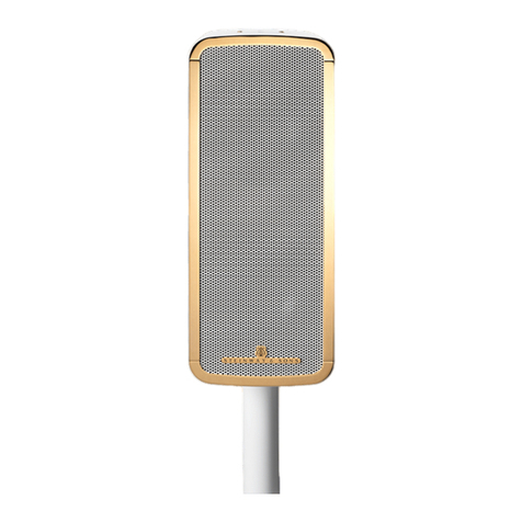
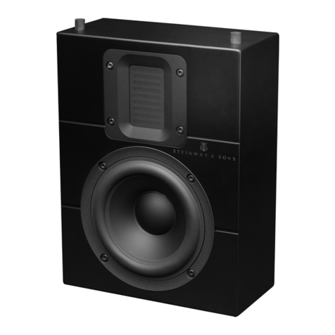
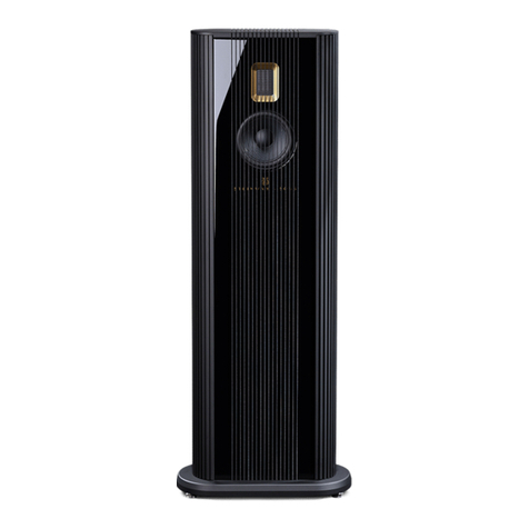
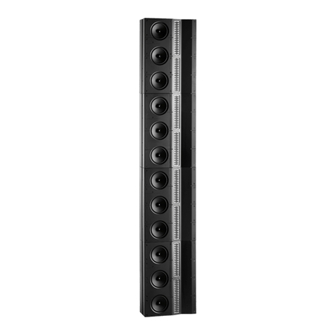
STEINWAY LYNGDORF S-SERIES User manual

[Skriv tekst]
S - SERIES
IN-WALL SERIES
INSTALLATION MANUAL
VERSION 2.2

2
S-15 AND S210 ................................................................................................... 4
IN-WALL SERIES, S-15IW AND S-16IW .......................................................... 13
S-15IW AND S-16IW WITH GRILLS ................................................................. 38
IN-CEILING S-16IW .......................................................................................... 64

3
INTRODUCTION
Please read all material carefully prior to installation. If you need additional assistance, contact your
Steinway Lyngdorf representative or email service@steinwaylyngdorf.com.
COMPLIANCE
WEEE
The European Parliament and the Council of the European Union have issued the Waste Electrical
and Electronic Equipment Directive. The purpose of the Directive is to prevent waste of electrical and
electronic equipment and to promote reuse, recycling, and other forms of waste recovery. Steinway
Lyngdorf products and the accessories packed with them are subject to the WEEE Directive. Please
dispose of any waste materials in accordance with your local recycling regulations. Products and
equipment which must be collected for reuse, recycling, and other forms of recovery are marked with
the icon of the crossed-out waste receptacle.
FCC
Steinway Lyngdorf products and accessories comply with parts 15 and 68 of the FCC rules. Operation
is subject to the following two conditions: (1) this device may not cause harmful interference; and (2)
this device must accept any interference received, including any interference that may cause
undesired operation. Changes or modifications not expressly approved by the party responsible for
compliance could void the user’s authority to operate the equipment. Equipment marketed to a
consumer must be capable of complying with the necessary regulations in the configuration in which
the equipment is marketed.
4
INSTALLATION MANUAL
S-15 AND S210

5
UNPACKING .................................................................................................................................. 6
INVENTORY .................................................................................................................................. 6
POSITIONING OF PRODUCTS .................................................................................................... 7
MOUNTING BOUNDARY WOOFER FEET ................................................................................... 9
BOUNDARY WOOFER FRONT CLOTH ....................................................................................... 9
S-15 WALL BRACKET ................................................................................................................. 10
S-15 ON-CEILING BRACKET.................................................................................................... 101
S-15 TABLE STAND (OPTIONAL ACCESSORY)....................................................................... 12

6
UNPACKING
Carefully remove the loudspeaker units and accessories from the carton, and check for shipping
damage. Contact both the shipper and your Steinway Lyngdorf representative immediately if products
bear any sign of damage. All Steinway Lyngdorf equipment is carefully inspected before leaving our
factory. Note: Keep the shipping carton and all packing material for future use or in the unlikely event
that products require servicing. If products are shipped without the original packing, damage could
occur and void the warranty.
INVENTORY
Check the list below to ensure that all necessary product components have been delivered. Report all
discrepancies to your Steinway Lyngdorf representative immediately.
Delivered with S-15 loudspeaker:
1 x S-15 loudspeaker
1 x wall bracket
4 x washers for wall bracket
1 x Torx Allen key
4 x rubber pads
Delivered with S-210 boundary woofers:
1 x S-210 boundary woofer
4 x rubber feet

7
POSITIONING OF PRODUCTS
S-15 Loudspeaker
The recommended height from floor to center of the tweeter in the S-15 is:
1m / 3ft. for use as front speakers / stereo speakers
1.8m / 6ft. for use as surround speakers
If possible, the wall should be constructed with the positioning of speakers in mind.
Whether placing the S-15 on its rubber feet, the optional table-stand, or the optional floor-stand, we
recommend having it parallel to the back wall and as close to the wall as possible.

8
S-210 Boundary Woofer
We recommend placing the boundary woofers in a corner position (fig 1). Always place the boundary
woofer as close to the wall as possible without touching it.
If a corner placement isn’t possible, the boundary woofers must be placed up against a minimum of 1
wall as shown in fig 2. There must be at least 10 cm / 4 in from the driver unit to the wall.
Fig 1. Fig 2.

9
MOUNTING BOUNDARY WOOFER FEET
After locating the optimal positions for the boundary woofers, mount the supplied feet to achieve
optimal stability. The boundary woofers are not intended to be used without the feet*.
To mount the feet on the boundary woofers, gently lay the woofer on its back on a soft surface to
prevent any damage or scratches.
After mounting the feet, gently bring the boundary woofer to its upright position in the selected
location. Once upright, adjust the feet to give optimal support.
(*) Please note that the feet can leave black marks if the speaker is pushed or dragged.
BOUNDARY WOOFER FRONT CLOTH
It is possible to remove the boundary woofer front cloth and the screws.
Remove the front cloth by holding it at the edges and pull away from the boundary woofer. Thereafter,
the 4 screws can be dismounted.

10
S-15 WALL BRACKET
When mounting the wall bracket, make sure the wall and screws can handle the total weight of the
bracket and speaker.
Remember to pull speaker wires from the location of the amplifiers to the bottom of the wall bracket.
Place the wall bracket against the wall. It must be placed so the two metal supports are at the top of
the bracket.
Make sure the wall bracket is level before fastening it loosely to the wall. Use the 4 x washers for
optimal support. The washers also makes it possible to finely adjust the level of the bracket. Adjust
the level if necessary and tighten the four screws.
Connect the speaker cable to the speaker in accordance with the connection label on the back of the
speaker. Place the speaker on the wall bracket and make sure it is pushed securely onto the two
metal supports.

11
S-15 ON-CEILING BRACKET
When mounting the on-ceiling bracket, make sure the ceiling and screws can handle the total weight
of the bracket and speaker.
Remember to pull speaker wires from the amplifiers to the back of the bracket.
1. Use the four screws to fasten the speaker plate onto the on-ceiling bracket, then mount the in-
ceiling bracket to the ceiling.
2. Attach the speaker wires and fasten the small speaker cover to the speaker.
3. Push the S-15 into the two top metal supports on the on-ceiling bracket and fasten it by using
the two screws.

12
S-15 TABLE STAND (OPTIONAL ACCESSORY)
To mount the S-15 table stand:
1. Unscrew the small cover using the included Torx Allen key.
2. Pull the speaker wire through the hole in the table stand.
3. Attach the speaker wire to the speaker terminals.
4. Mount the table stand and fasten it with the screws supplied with the table stand.

13
INSTALLATION MANUAL
IN-WALL SERIES, S-15IW AND S-16IW

14
UNPACKING ................................................................................................................................ 15
INVENTORY ................................................................................................................................ 15
POSITIONING OF PRODUCTS .................................................................................................. 16
USING THE CUTOUT TEMPLATE FOR RETROFIT APPLICATIONS ...................................... 24
SPEAKER INSTALLATION .......................................................................................................... 25

15
UNPACKING
Carefully remove the speaker and accessories from the carton, and check for shipping damage.
Contact both the shipper and your Steinway Lyngdorf representative immediately if products bear any
sign of damage or if there is a discrepancy in the number of packages received. All Steinway Lyngdorf
equipment is carefully inspected before leaving our factory. Note: Keep the shipping carton and all
packing material for future use or in the unlikely event that products require servicing. If products are
shipped without the original packing, damage could occur and void the warranty.
INVENTORY
Check the list below to ensure that all necessary product components have been delivered. Please
report all discrepancies to your Steinway Lyngdorf representative immediately.
Cutout
template
2mm Allen Key
2 x Installation Bracket
4 x Angled Metal Bracket
Mounting Distance Guide
2 x 6mm / 1/4in thick distance
block
Screws for Angled Metal
Bracket and Mounting
Distance Guide

16
POSITIONING OF PRODUCTS
The center of the front speaker tweeter should be in level with the primary listening position,
which is approximately 1m / 3ft depending on the height of the seat.
Surround and rear speakers tweeter center should be 180cm / 6ft from the floor.
Model IW-26H
The IW-26H speaker weighs 12.2kg / 26.9lbs. Screws and wall framing must be able to support this
weight.
This speaker has screw terminals; please use a Phillips head screwdriver.
Recommended minimum up to 16m / 50ft: AWG 14/4 or 4-lead 2mm2.
Recommended minimum from 16m / 50ft and up: AWG 12/4 or 4-lead 3.5mm2.
Recommended maximum: AWG 10/4 or 4-lead 5mm2.
Cutout Template

17
Installation Bracket
The distance between the top and bottom installation bracket must be 324mm / 12.75in.
The width of the installations bracket is 60cm / 26.6in.

18
Model IW-26V
The IW-26V speaker weighs 11.3kg / 24.9lbs. Screws and wall framing must be able to support this
weight.
This speaker has screw terminals; please use a Phillips head screwdriver.
Recommended minimum up to 16m / 50ft: AWG 14/2 or 2-lead 2mm2
Recommended minimum from 16m / 50ft and up: AWG 12/2 or 2-lead 3.5mm2
Recommended maximum: Double AWG 10/2 or 2-lead 5mm2
Cutout Template

19
Installation Bracket
The distance between the top and bottom installation bracket must be 584mm / 23in.
The width of the installations bracket is 35.5cm / 14in.

20
S-15IW
The S-15IW speaker weighs 3.5 kg / 7.7 lbs. Screws and wall framing must be able to support this
weight.
This speaker has screw terminals, please use a Phillips head screwdriver.
Recommended minimum up to 16m / 50ft: AWG 14/2 or 2-lead 2mm2
Recommended minimum from 16m / 50ft and up: AWG 12/2 or 2-lead 3.5mm2
Recommended maximum: Double AWG 10/2 or 2-lead 5mm2
Cutout Template
This manual suits for next models
1
Table of contents
Other STEINWAY LYNGDORF Speakers manuals

STEINWAY LYNGDORF
STEINWAY LYNGDORF Steinway & Sons Marine Speaker User manual

STEINWAY LYNGDORF
STEINWAY LYNGDORF Steinway & Sons Model O User manual

STEINWAY LYNGDORF
STEINWAY LYNGDORF Steinway & Sons Model C User manual

STEINWAY LYNGDORF
STEINWAY LYNGDORF Steinway & Sons LS User manual

STEINWAY LYNGDORF
STEINWAY LYNGDORF IW-15 User manual

STEINWAY LYNGDORF
STEINWAY LYNGDORF IW-66 User manual