STEINWAY LYNGDORF Steinway & Sons LS User manual

[Skriv tekst]

Steinway & Sons Model LS – Installation Manual, version 2.1
2
TABLE OF CONTENTS
TABLE OF CONTENTS ..................................................................................................... 2
INTRODUCTION ............................................................................................................. 3
COMPLIANCE ................................................................................................................ 3
MODEL LS MUSIC SYSTEM PRE-INSTALLATION .............................................................. 4
INSTALLATION ............................................................................................................... 6
TRADEMARKS.............................................................................................................. 17
SERVICE INFORMATION .............................................................................................. 18

Steinway & Sons Model LS – Installation Manual, version 2.1
3
INTRODUCTION
Please read all material carefully prior to installation. If you need additional assistance, contact your Steinway
Lyngdorf representative or email service@steinwaylyngdorf.com.
COMPLIANCE
WEEE
The European Parliament and the Council of the European Union have issued the Waste Electrical and
Electronic Equipment Directive. The purpose of the Directive is to prevent waste of electrical and electronic
equipment and to promote reuse, recycling, and other forms of waste recovery. Steinway Lyngdorf products
and the accessories packed with them are subject to the WEEE Directive. Please dispose of any waste materials
in accordance with your local recycling regulations. Products and equipment which must be collected for
reuse, recycling, and other forms of recovery are marked with the icon of the crossed-out waste receptacle.
FCC
Steinway Lyngdorf products and accessories comply with parts 15 and 68 of the FCC rules. Operation is subject
to the following two conditions: (1) this device may not cause harmful interference; and (2) this device must
accept any interference received, including any interference that may cause undesired operation. Changes or
modifications not expressly approved by the party responsible for compliance could void the user’s authority
to operate the equipment. Equipment marketed to a consumer must be capable of complying with the
necessary regulations in the configuration in which the equipment is marketed.

Steinway & Sons Model LS – Installation Manual, version 2.1
4
MODEL LS MUSIC SYSTEM PRE-INSTALLATION
Unpacking the Model LS
Carefully remove the loudspeaker units and accessories from the carton and check for shipping damage.
Contact both the shipper and your Steinway Lyngdorf representative immediately if the unit bears any sign of
damage from mishandling. Note: Keep shipping carton and packing material for future use or in the unlikely
event that the unit needs servicing. If this unit is shipped without the original packing, damage could occur and
void the warranty.
Inventory
Check to ensure that all necessary product components have been delivered. Report all discrepancies to your
Steinway Lyngdorf representative immediately.
• Model LS left, right, center, surround, and boundary woofer loudspeaker units (depending on setup).
Brackets for securing the individual loudspeaker units to each other are attached to the units prior to
shipping.
• Brackets for securing the top and bottom speaker unit in each stack.
Note that the Model LS boundary woofer does not include these brackets. Instead, rubber feet and metal
spikes are included for mounting on the bottom boundary woofer in each stack. Your choice of feet or spikes
depends on the floor surface on which the boundary woofers will stand. Use spikes for carpeted floors, and
the rubber feet for hardwood or tiled floors.

Steinway & Sons Model LS – Installation Manual, version 2.1
5
• In-wall-mounted brackets for securing the top of each stack to the wall. No in-wall-mounted brackets
are necessary with Model LS boundary woofers, nor are such brackets included with the boundary
woofers.
• Spike sheets for Model LS left, right, center, and surround loudspeaker stacks, one spike sheet per
stack. These sheets protect the floor against damage from the spikes mounted on the bottom of each
loudspeaker stack.
Additional items in inventory include:
• SpeaKon connectors (NL 4 FC)

Steinway & Sons Model LS – Installation Manual, version 2.1
6
INSTALLATION
Prepare the Wall for the Speaker Stacks
For proper mounting of a Model LS loudspeaker stack, a rectangular cutout with the following dimensions
must be made in the wall:
Model LS Left, Center, Right and Surround
• Height
o For a stack of 4 units: at least 206.3 cm (81.22 in) and no more than 207.5 cm (81.69 in) in
height.
o For a stack of 5 units: at least 255.3 cm (100.62 in) and no more than 256.5 cm (101.78 in) in
height.
o For a stack of 6 units: at least 304.4 cm (119.8 in) and no more than 305.4 cm (120.2 in) in
height.
o For each additional unit: add 49.2 cm (19.4 in) to the height of the wall cutout. The spikes
mounted on the bottom loudspeaker unit can be adjusted so that the stack fits the wall
cutout precisely.
• Width at least 35.5 cm (13.98 in) and no more than 36.0 cm (14.17 in)
• Depth at least 15.5 cm (6.1 in)
Model LS Boundary Woofer
• Height (number of speakers in stack) x 73.8 cm (29.1 in) + (height of feet or spikes)
• Width at least 35.5 cm (13.98 in) and no more than 36.0 cm (14.17 in)
• Depth at least 33.5 cm (13.2 in)

Steinway & Sons Model LS – Installation Manual, version 2.1
7
The Speakon loudspeaker cables for connection of stacks to the appropriate Model A1 amplifiers should exit
the wall behind each stack at the following positions:
• Model LS Left: 29.0 cm (11.4 in) above floor, along the vertical axis.
• Model LS Right: 29.0 cm (11.4 in) above floor, along the vertical axis.
• Model LS Center: 29.0 cm (11.4 in) above floor, 3.0 cm (1.2 in) to the left of the vertical axis.
• Model LS Surround: 45.5 cm (18.0 in) above floor, 5.0 cm (2.0 in) to the left of the vertical axis.
• Model LS Boundary Woofer: 13.0 cm (5.1 in) above floor, 8.0 cm (3.1 in) to the left of the vertical axis.

Steinway & Sons Model LS – Installation Manual, version 2.1
8
Example: Proper socket placement for mounting of a Model LS Center loudspeaker stack.
Arrange the individual speaker units in a stack. For each loudspeaker stack, place the loudspeakers with the
front side down on the floor, preferably close to the wall cutout in which the stack is to be mounted. Make
sure that the floor is covered with fabric – such as carpeting - to avoid scratching the loudspeakers.
NOTE! Before placing the LS Center loudspeakers front side down, lay down two rows of extra

Steinway & Sons Model LS – Installation Manual, version 2.1
9
material, such as Styrofoam, which can support the loudspeakers on each side of the tweeter units.
The tweeter units are fragile and cannot support the weight of the stack without being damaged.
Ensure that the two rows of Styrofoam extend beyond the bottom edge of the stack in such a way
that they, and not the tweeter units, support the weight of the stack when the stack is raised upright
and mounted in the wall cutout.
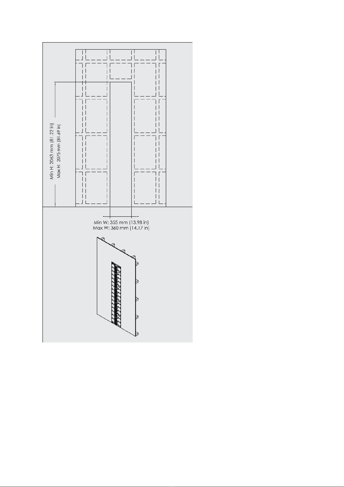
Place the loudspeakers in order, with the bottom loudspeaker in the stack closest to the bottom edge of the
wall cutout in which the stack is to be mounted. This facilitates easy mounting when connections are
complete, as the stack can be tilted directly into place.
Remove the Brackets from Each Speaker Unit
All Model LS loudspeaker units, including boundary woofers, are equipped with metal brackets from the
factory. When these brackets are mounted correctly on the left, right, and rear sides of the units, they align
and secure the individual units in a stack to each other. Using a TORX 30 type screwdriver, remove the screws
securing the brackets to the loudspeakers, keeping the brackets and screws close at hand.
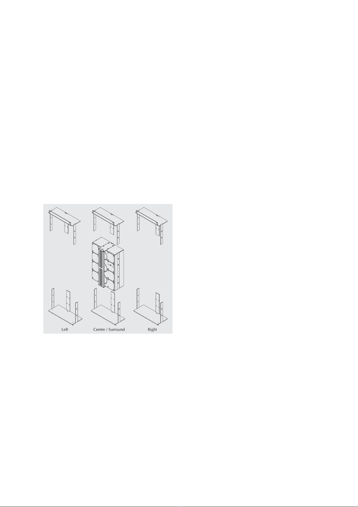
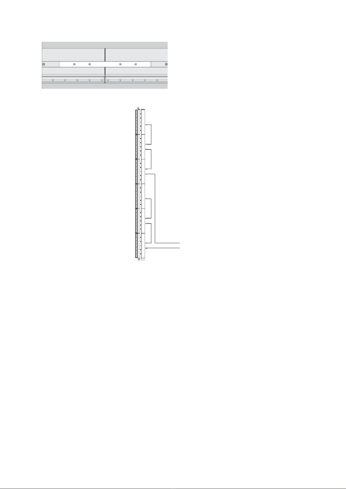
Mount the Side Brackets on Each Stack
Model LS boundary woofers, right, left, center, and surround loudspeakers: Using the screws you have just
removed from the side and rear brackets, secure the side brackets to the stack as shown below. The bracket
must bridge two loudspeakers in such a way that the bracket can be affixed to each loudspeaker with two
screws.
First, insert the screws into all four holes and tighten them by hand until the head of each screw protrudes 1-2
mm, then tighten the screws with a TORX 30 screwdriver. If you mount the bracket one screw at a time, there
is a risk that the last screw will not be fully aligned with the hole. Tightening the last screw can then result in
the screw thread being stripped, rendering the screw useless and resulting in an unstable loudspeaker stack.
When the side brackets are mounted on the stack correctly, there are two side brackets left over. These are to
be mounted on the rear of the stack, but only after the loudspeaker cables have been run as described below.

Steinway & Sons Model LS – Installation Manual, version 2.1
10
Daisy chain connection for Model LS right, left, center and surround loudspeakers in a stack of 6.

Steinway & Sons Model LS – Installation Manual, version 2.1
11
Daisy chain connection for Model LS right, left, center and surround loudspeakers in a stack of 4.
1:1 connection of Model LS boundary woofers

Steinway & Sons Model LS – Installation Manual, version 2.1
12
Connect the Loudspeaker Cables
Model LS right, left, center, and surround loudspeakers: The socket pairs on the rear of the Model LS
loudspeakers and the Speakon cables included with the loudspeakers facilitate connection of the individual
units in a stack in a daisy chain. As shown to the left, the cable connecting each stack to a Model A1 amplifier is
connected to the bottom socket on the bottom loudspeaker unit in each stack. A cable then connects the top
socket on the bottom loudspeaker to the bottom socket on the loudspeaker unit above it, and so on to the top
of the stack.
Model LS boundary woofers: Unlike the other Model LS loudspeakers, the boundary woofers must be
connected individually to their respective Model A1 amplifiers, and cannot be connected in a daisy chain.

Steinway & Sons Model LS – Installation Manual, version 2.1
13
Mount the Brackets for the Top and Bottom Loudspeakers in a Stack
Model LS right, left, center, and surround loudspeakers: Using the same TORX 30 screwdriver and the screws
you have just removed from the side and rear brackets, secure the dedicated top and bottom brackets to the
loudspeakers in their respective stacks as shown to the right. The top and bottom brackets for the Model LS
center loudspeaker are identical to the top and bottom brackets for the Model LS surround loudspeakers.
Model LS boundary woofers: There are no top or bottom brackets for the LS boundary woofers. For the
bottom unit in a stack, attach spikes or rubber feet, depending on the floor surface. For middle and top units in
a stack, attach rubber feet to each unit to stabilize the stack, as the rubber feet fit precisely into corresponding
recessions in the boundary woofers beneath.

Steinway & Sons Model LS – Installation Manual, version 2.1
14
Mount the Remaining Side Brackets
Model LS boundary woofers, right, left, center, and surround loudspeakers: When cable connections are
complete, use a TORX 30 screwdriver to mount the remaining side brackets on the rear of the loudspeaker
stacks, bridging the individual loudspeakers as shown previously. The brackets on the rear of the loudspeaker
stacks will partially cover the socket panels, so make sure connections are complete before mounting the
remaining brackets on the rear of the stack.
Mount the Wall Bracket in the Wall
Model LS right, left, center, and surround loudspeakers: Mount the wall bracket on the bottom side of the
horizontal stud at the top of the wall cutout as shown, fixing the bracket to the stud with five screws. Note that
the purpose of the wall bracket is to stabilize the stack and not to bear its weight; the stack stands on four
spikes attached to the bottom bracket, and these spikes are placed in their respective holes in the spike sheet,
which protects the floor.
NOTE! Never use countersunk screws when mounting the loudspeaker units.
There are no top brackets for the LS boundary woofers.

Steinway & Sons Model LS – Installation Manual, version 2.1
15
Mount the Speaker Stack in the Wall
When all connections are complete and the relevant brackets mounted on the loudspeakers and in the wall
cutout, the stack can then be mounted in the wall cutout. Before mounting a loudspeaker or boundary woofer
stack on a non-carpeted surface, such as a wooden floor, first place the spike sheet on the floor in the wall
cutout so that the front edge of the spike sheet is aligned with the outer surface of the wall. This ensures that
the front of the stack protrudes from the wall the proper amount for optimal sound performance. Tilt the
stack until it stands in an upright position in the wall cutout, ensuring that the spikes attached to the bottom
bracket are aligned with their respective holes in the spike sheet.
NOTE! For your own safety, do not attempt to raise the stack by yourself. As a rule of thumb, there
should be one person involved in lifting a loudspeaker stack for every two loudspeaker units in the
stack; so a stack of six loudspeaker units requires at least three people to lift. For stacks of boundary
woofers, there should be one person involved in lifting for every individual unit in the stack, so a stack
of two boundary woofers requires at least two people to lift.
Check that the screw holes in the stack’s top bracket are aligned with their corresponding holes in the wall
bracket. If not, lower the stack to the floor once more and adjust the height of the spikes. This is done by
rotating the spikes: clockwise to decrease the height of the stack, and counter-clockwise to increase it.
Similarly, you can adjust the height of a Model LS boundary woofer stack by adjusting the height of the rubber
feet or spikes on the bottom unit in the stack. When the holes in the loudspeaker stack’s top bracket are
aligned with the holes in the wall bracket, you can then secure the stack to the wall bracket with the screws
included with the system. The screws must be tightened completely.

Steinway & Sons Model LS – Installation Manual, version 2.1
16
Please note that there will be a space of roughly 1-2 millimeters between the heads of these screws and the
front side of the stack’s top bracket, even after the screws have been tightened completely. This ensures that
the vibration of the loudspeaker during use is not transplanted to the wall construction, while at the same
time ensuring that the stack cannot tip over.

Steinway & Sons Model LS – Installation Manual, version 2.1
17
TRADEMARKS
DTS is a registered trademark & the DTS logos and Symbol are trademarks of DTS, Inc. Manufactured under
license under U.S. Patent #’s: 5,451,942; 5,956,674; 5,974,380; 5,978,762; 6,226,616; 6,487,535 & other U.S.
and worldwide patents issued & pending. DTS is a registered trademark and the DTS logos, Symbol, DTS-HD
Master Audio are trademarks of DTS, Inc. © 1996-2008 DTS, Inc. All Rights Reserved.
HDMI, the HDMI Logo and High-Definition Multimedia Interface are trademarks or registered trademarks of
HDMI Licensing LLC.
Dolby and the double-D symbol are registered trademarks of Dolby Laboratories.
This product incorporates technology that is protected by U.S. patents and other intellectual property rights.
Use of this technology must be authorized by Macrovision, and is intended for home and other limited viewing
uses only, unless otherwise authorized by Macrovision. Reverse engineering or disassembly is prohibited.
This item incorporates copy protection technology that is protected by U.S. patents and other intellectual
property rights of Rovi Corporation. Reverse engineering and disassembly are prohibited.

Steinway & Sons Model LS – Installation Manual, version 2.1
18
SERVICE INFORMATION
In order to obtain warranty service you must contact your original dealer or the Steinway Lyngdorf distributor
of the region or country where you are located. If you have trouble locating an authorized representative,
please contact the Steinway Lyngdorf Customer Service Department using the contact information at
www.steinwaylyngdorf.com, or you may email service@steinwaylyngdorf.com.
Steinway Lyngdorf
Ulvevej 28
DK 7800 Skive
Denmark
In some cases, the Customer Service Department may solve a service problem without the need of repair or
any other measures, thereby avoiding further inconvenience or delay. In some cases it may be necessary to
return the equipment to Steinway Lyngdorf or an authorized service provider for repair; therefore, it is
recommended that you save your original packing materials. Steinway Lyngdorf will not be responsible for any
damage due to unauthorized packing or shipment in non-original packing materials. If return is made in
authorized packaging, risks are borne by Steinway Lyngdorf. Additional charges may occur if new packing
materials are required for return shipment.

Steinway & Sons Model LS – Installation Manual, version 2.1
19
Table of contents
Other STEINWAY LYNGDORF Speakers manuals

STEINWAY LYNGDORF
STEINWAY LYNGDORF Steinway & Sons Marine Speaker User manual

STEINWAY LYNGDORF
STEINWAY LYNGDORF Steinway & Sons Model C User manual

STEINWAY LYNGDORF
STEINWAY LYNGDORF S-SERIES User manual

STEINWAY LYNGDORF
STEINWAY LYNGDORF IW-66 User manual

STEINWAY LYNGDORF
STEINWAY LYNGDORF IW-15 User manual

STEINWAY LYNGDORF
STEINWAY LYNGDORF Steinway & Sons Model O User manual