stellar labs SLP-200 100W x 2 CH User manual

Professional Sound Owners Manual
Reinforcement Amplifiers
Model # Power Output
SLP-200 100W x 2 H
SLP-300 150W x 2 H
SLP-600 300W x 2 H
SLP-900 450W x 2 H
©2010 M M Electronics Stellar Labs™
Division of M M Electronics
enterville, Ohio
www.mcmelectronics.com

SLP Series Amplifiers
Owners Manual
2
Safety Information
The lightning bolt within a
triangle is intended to
alert the user to the
presence of un-insulated
dangerous voltage levels
within the product’s
enclosure.
This voltage may be of
sufficient magnitude to
constitute an electric
shock risk.
To reduce the risk of electric shock,
do not remove cover of this device.
There are no user serviceable parts
inside.
Refer servicing only to qualified
service personnel.
The exclamation point
within a triangle is
intended to alert the
user to important
operating and
maintenance (servicing)
instructions in the
literature accompanying
the appliance.
Safety Precautions
•Read and retain these instructions
•Follow all instructions and heed warnings
•Do not use this device near water
•If the surface becomes dirty, clean only with dry cloth, do not use solvents or thinners
•Install in accordance with the manufacturer’s instructions
•Do not block ventilation openings
•Do not install near heat sources such as radiators, heat registers, stoves, or other
devices that produce heat
•Do not defeat the safety purpose of the grounded plug. This plug has two blades and a
third ground prong. The wide blade or third prong are provided for your safety. If the
provided plug does not fit into your outlet, consult an electrician for replacement of the
obsolete outlet
•Protect the power cord from being stressed at the plugs, convenience receptacles,
and where they exit the amplifier
•Only use accessories specified by the manufacturer
•Unplug the device during lightning storms or when unused for an extended time
•Refer all servicing to qualified personnel
•This device must not be exposed to water in any way. No object filled with liquids
should be placed on apparatus

SLP Series Amplifiers
Owners Manual
3
FEATURES
•Two channel stereo amplifier with selectable bridged mono operation
•Rugged 2RU rack mount or tabletop enclosure
•Independent 42 position detent left/right front panel level controls
•LED indicators for POWER, BRIDGE, SIGNAL, LIP AND PROTE TION modes
•Efficient fan cooling
•Balanced XLR inputs with feed through XLR output
•Unbalanced R A line level inputs
•Selectable limiter
•Selectable input ground-lift
•Heavy duty binding post outputs
•Twist lock speaker connections (compatible with Speakon connectors) for LEFT, RIGHT and
BRIDGED output
•117VA /60HZ operation with detachable IE type power cord
APPLICATIO S
These amplifiers are suitable for sound reinforcement applications including DJ, live music, theater and
stage, monitoring, and any other demanding two channel music application. In bridged mode, these also
perform especially well as subwoofer power amplifiers. Locations include schools and universities, houses
of worship, residential distributed audio, clubs, sports bars, restaurant and other public locations.
They are designed for continuous duty use in demanding environments and when installed properly will
provide years of reliable, trouble free operation.
FRO T PA EL
1. Red Protection Indicator
Under normal operation, this indicator will be off. It will illuminate red to indicate that a fault has
occurred, and the amplifier has shut down to prevent damage. The user should determine the cause of the
fault before continuing use. ontinually causing the PROTE TION circuit to trip may cause permanent
damage to the amplifier. hannel A and hannel B protection functions operate independently.
2. Yellow Clip Indicator
As the amplifier is driven to its maximum power output, the output signal may distort or clip. Under
heavy use, these indicators may light very intermittently, however this should only be instantaneous and
brief. Driving the amplifier to clip may be damaging to connected speaker systems, even if the speaker
system is capable of handling the rated output of the amplifier. Engaging the LIMITER function on the rear
panel will prevent the amplifier from clipping. hannel A and hannel B clip indicators operate
independently.
3. Green Signal Indicator
These indicators will blink with brightness consistent with the input signal level. Under normal use, these
indicators will be either intermittently or continuously lit. hannel A and hannel B signal indicators
operate independently.
4. Blue Bridge Indicator
These indicators illuminate to indicate the amplifier is operating in BRIDGED mode. Selection of this mode
is accomplished via the rear panel mounted switch. hannel A and channel B BRIDGE indicators operate in
unison.
5. Blue Power Indicator

SLP Series Amplifiers
Owners Manual
4
Indicates the master power switch on the front panel is in the ON position.
6. Rotary Gain Controls
Independent gain control for each hannel A and hannel B. ontrols are high quality 42 position detent
controls that allow independent level adjustment of each channel.
7. Master POWER Switch
Rocker style switch provides ON/OFF control of the amplifier.
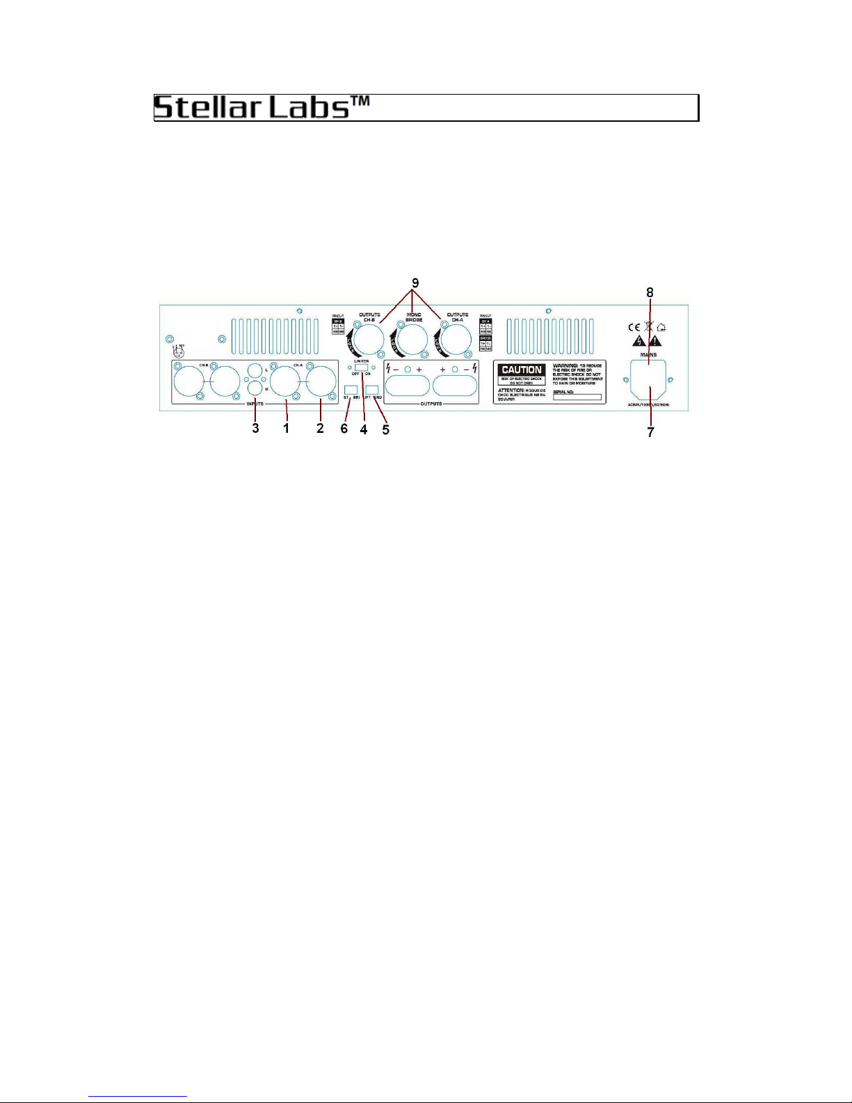
REAR PA EL
1. Balanced Line Level Input
Independent hannel A and hannel B female XLR connectors accept line level input from mixing console
or similar audio source. This input is designed to accept signal from prosound equipment, typically +4dBv.
2. Feedthrough Balanced Output
Independent hannel A and hannel B male XLR connections are tied directly to the female input
connections, and are intended to provide feedthrough to a second amplifier. The signal level at this
connection will match exactly that of the XLR input.
3. Unbalanced Line Level Input
Independent hannel A and hannel B female R A style connectors accept unbalanced line level inputs
from standard consumer type audio sources. This includes D and DVD players, tape decks, computer
sound cards, MP3 players, RE outputs on stereo receivers and similar. This input accepts standard line
level signals, typically –10dBv.
4. Limiter O /OFF
This selector engages the limiter function of the amplifier. While engaged, the limiter will automatically
decrease amplifier gain, when needed, to prevent the amplifier from clipping. This is useful as it will
prevent amplifier and speaker damage, as well as prevent sound distorting effects of a clipping amplifier.
The disadvantage of engaging this function is that it can reduce overall dynamic range, especially at high
volume levels.
5. Ground Lift
This selector disengages the input shield connections (outer shield on R A inputs or Pin-1 on the XLR
inputs) from the chassis and earth ground. This is often necessary to eliminate ground loops that exist
between multiple components that are independently grounded. These ground loops manifest themselves
as noise, buzzing or 60Hz hum when present. Two position slide switch in left position, ground engaged.
In the right position, ground is disengaged or "lifted".
6. Stereo / Bridged Selector
This two position selector selects between stereo or bridged mono modes of the amplifier. In the left
position, the two amplifier channels function independently allowing stereo operation. With this selector in
the RIGHT position, the amplifier channels are BRIDGED, effectively adding the two channels together, to
create one channel with twice the power output. This is especially common when the amplifier is used to
power a single, large subwoofer. OTE: it is critical that correct speaker connections are utilized in this
mode. See the following details for information regarding this.
7. Power Input
This standard IE type power connection accepts 117VA , 60Hz supply voltage only. This amplifier is not
suitable for use in countries utilizing different mains voltage.

SLP Series Amplifiers
Owners Manual
5
8. Fuse
The fuse holder is built into the IE connector, and the power cord must be unplugged from the unit to
gain access. Replace only with same type 5mm x 20mm, fast acting fuse. See specifications at the end of
this manual for proper fuse size.
9. Speaker Output Connections
This amplifier is designed to accommodate a variety of speaker configurations, depending upon specific
needs. However, when connecting speaker systems, it is critical that impedance be considered in order to
ensure reliable operation and prevent permanent damage to the amplifier.
Impedance
In stereo mode, this amplifier can support speaker loads of 4Ω and higher, on each channel. In
bridged mono mode, the amplifier will support a single speaker load of 8Ω or higher.
In stereo mode, if more than one pair of speakers are to be connected, each speaker MUST be
8Ω or higher, otherwise permanent damage will occur. If 4Ω speakers are to be used, ONLY one
pair may be connected.
In bridged mono mode, only one 8Ω speaker may be connected. 4Ω speakers cannot be
connected to this amplifier while in bridged mode. If two speakers are to be connected to this
amplifier while in bridged mode, they MUST be 16Ω or higher.
Binding Posts
Heavy duty binding posts are intended for bare wire speaker connection. It is important that
proper polarity be observed when connecting the pair of speakers. When the amplifier is in stereo
mode, Individual + and – connections are provided and clearly marked for connection of a
speaker pair. When the amplifier is in BRIDGED mode, only connect to the two + (RED)
connections, as the two – (BLA K) connectors are not used.
Twist Lock Connectors
These connectors are designed to mate with industry standard Speakon™ connectors. In is
important to note that separate connections are used for bridged and stereo operation.
Specifications SLP-200 SLP-300 SLP-600 SLP-900
RMS Power Output
Stereo 8Ω 65W x 2 H 100W x 2 H 200W x 2 H 300W x 2 H
Stereo 4Ω 100W x 2 H 150W x 2 H 300W x 2 H 450W x 2 H
Bridged 8Ω 200W x 1 H 300W x 1 H 600W x 1 H 900W x 1 H
Frequency Response
10Hz ~ 50KHz ±1.5dB
Max Input Level 21dBV / 9.0V (limiter on)
S/N Ratio >90dB >95dB >105dB >120dB
Damping Factor >200 >300 >350 >400
Protection Short circuit, current limiting, thermal cutoff,
D fault, A mains transients, soft start, A line fuse
ooling Variable speed fan
Power onsumption 200W 300W 500W 700W
Fuse Protection
Dimensions 3.5" (H) x 19" (W)x 15.35" (D) / 2RU
Weight 17.6 lbs. 22.0 lbs. 26.5 lbs. 31.0 lbs.

SLP Series Amplifiers
Owners Manual
6
M M ustom Audio and Stellar Labs products are warranted, by M M Electronics,
against manufacturer defects for a period of one year from the original date of
purchase. This warranty is limited to manufacturer defects, in either materials or
workmanship. M M Electronics, or any other worldwide divisions of Premier Farnell
PL , are not responsible for any consequential or inconsequential damage to any
other component, structure or the cost of installation or removal of said items.
For questions or specific information regarding warranty replacement or repair,
contact:
MCM Electronics
www.mcmelectronics.com
800-543-4330
This manual suits for next models
7
Table of contents
Other stellar labs Amplifier manuals

stellar labs
stellar labs 50-4609 User manual

stellar labs
stellar labs 30-2471 User manual

stellar labs
stellar labs DA-250 User manual

stellar labs
stellar labs PLA300 User manual

stellar labs
stellar labs SLA150 User manual

stellar labs
stellar labs 50-20810 User manual

stellar labs
stellar labs STA2000 Series User manual