manuals.online logo
Brands
  1. Home
  2. •
  3. Brands
  4. •
  5. stellar labs
  6. •
  7. Antenna
  8. •
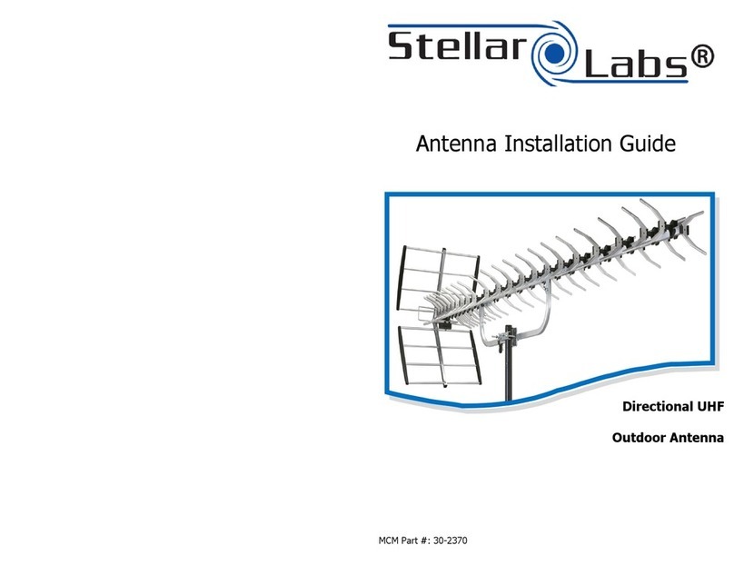
  9. stellar labs 30-2426 User manual

stellar labs 30-2426 User manual

Antenna Installation Guide
MCM Part #: 30-2426
Quad Bay Outdoor
UHF/HDTV Bowtie Antenna
Safety Guidelines and Procedures
Listed below are extremely important safety guidelines that are to be followed
when installing your Stellar Labs® antenna. Not following these guidelines can
result in death or serious injury.
 Locate and take actions to avoid power lines and other wires in your work space.
 Do not climb onto a slick, icy, or wet roof.




or pull out.)
 Wear season
rubber-





Mast Grounding
A copper-
cial clamps that provide a solid connection between the ground wire and grounding rod
should be used.
Grounding the Signal Cable
TV Antennas and signal cable can accumulate static electrical charges that also increases the
chances of lightning strike. To properly dissipate this static electricity, a grounding block
should be used. The grounding block is connected to the signal cable at a point close to
where the signal cable enters the building (a signal splitter that has a tab for ground on it
will also work.) One end of a ground wire is attached to the grounding block. The other end
of the wire is connected directly to the grounding rod. An antenna installation is not properly
grounded unless both a mast ground and an grounding block are installed correctly.
Specifications
Frequency:
Channel:
Impedance:
# of Elements:
Gain:
F-B Rao:
Beam Width:
Length:
470~862MHz
-
21-69
75Ω
2
10-14dB
22dB
H 60°
31.5"
Avoid installations in high areas on windy days.
Inspect the ladder you plan on using to ensure it is in safe operable condition.
Do not position your ladder at an angle steeper than 70˚.
Do not climb on roofs that have curled or worn shingles. (Old shingles break easily
-appropriate attire that is neither too loose or too tight. Always wear
Wear a
s
p
o
a
le
ir
d
o
s
f
h
d
o
u
e
r
s
a
b
w
le
it
h
g
l
g
o
o
v
o
e
d
s
t
g
h
r
a
ip
t
.
also allows normal mobility of your hands.
Assembly Instructions
Look around your work area to observe for any potential dangers.
Never climb onto a high location while alone.
Step 1: Attach mounting brackets “A” (as pictured below) to one
of the two reflectors
using the provided bolts and wing nuts. (as shown in “Figure “A”)
Avoid installing your antenna underneath tree branches or other overhanging objects.
Antennas should be installed away from power lines and other wires a distance equal
to at least two times the combined length of the mast and antenna.
Grounding Procedure
The NEC mandates that the antenna mast and mount be grounded directly. There can be no
splices or connections in the ground wire between the mast and the grounding rod. First,
attach one end of a No. 8 or No. 10
copper ground wire
to the antenna mast. One of the
bolts on the antenna mount can be used as a connection point. Masts that are painted or
coated can have their coating scraped off on the area where they make contact to the
mount. This will ensure a proper connection between the mast and the mount. Next, run the
ground wire to the ground as directly as possible. Wire staples can be used to secure the
ground wire against the side of a building. Avoid making right angle or sharper turns with
the ground wire. Lightning has difficulty making such a turn and therefore may discharge
w
in
i
t
r
o
e
t
m
he
u
s
b
t
u
b
il
e
d
i
c
n
o
g
n
.
n
M
e
a
c
k
te
e
d
g
t
r
o
o
u
a
n
g
d
r
o
w
u
ir
n
e
d
t
in
u
g
rn
r
s
o
a
d
s
.
s
W
m
a
o
t
o
e
t
r
h
f
a
a
u
n
c
d
e
a
ts
s
a
s
n
lig
d
h
/o
t
r
a
p
s
ip
p
e
o
s
s
s
a
ib
re
le
n
.
o
T
t
h
a
e
c
g
c
r
e
o
p
u
ta
n
b
d
l
e.
coated steel ground rod driven at least three feet into the ground is required. Spe-
Mounting Bracket A
Figure A
Assembly Instructions
Step 2: Connect one of the reflectors utilizing bracket “A” to one of the reflectors
without a bracket using the provided bolts and wing nuts. (as shown in “Figure “B”)
Step 3: Insert the stand-off connectors into the corresponding mounting
location on each of the reflector assemblies. (as shown in “Figure C”)
Figure B
Figure C
Figure D
Step 4: Unfold the array assembly and tighten using wing nut located in the
center. (as shown in “Figure D”)
Figure E
Step 5:
Attach array and reflector assembly together using the stand-off connectors
on the reflector assembly, and the corresponding mounting location on the array
assembly. (as shown on “Figure E”)
Assembly Instructions
MCM Part #: 30-2426 MCMelectronics.com
This product carries a limited 90 day warranty, which does not apply if the
product has been damaged, deteriorates, malfunctions or fails from:
improper installation, misuse, abuse, neglect, accident, tampering,
modification of the product as originally manufactured by Stellar Labs® in
any manner whatsoever, usage not aligned with product instructions or
acts of nature such as damage caused by wind, lightning, ice or corrosive
environments such as salt spray and acid rain. This Limited Warranty also
does not apply if the product becomes unable to perform its' intended
function in any way as a result of the television signal provider making any
changes in technology or service. Should a failure be determined covered
by the warranty, it will be the sole discretion of MCM Electronics to repair or
replace the product. This warranty covers the product only, and does not
include any additional product or expense incurred. No liability outside the
product itself is implied.
RETURN AUTHORIZATION POLICY
A Return Material Authorization (RMA) is required prior to returning any
product to Stellar Labs® under this warranty policy. Please call our
Customer Service at (877) 626-3532 or send an email to
[email protected] to obtain an RMA number. Enclose
the product in a prepaid package and write the RMA number in large, clear
numbers on the outside of the package. To avoid confusion or
misunderstanding, a shipment(s) without an RMA number(s) or an
unauthorized return(s) will be refused and returned to Customer freight
collect.
Warranty Information
Final assembly should resemble “Figure F”
Step 6:
Connect the provided coaxial cable to the F connector on the center of the
array assembly.
Figure F

Other stellar labs Antenna manuals

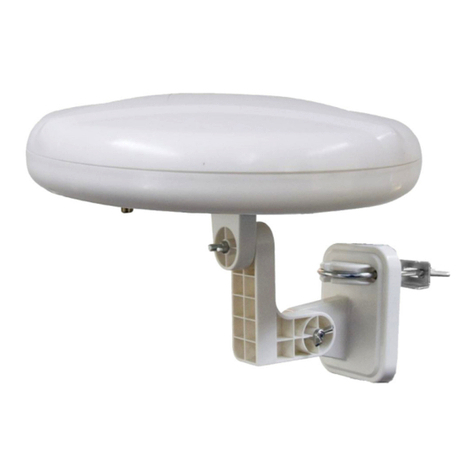
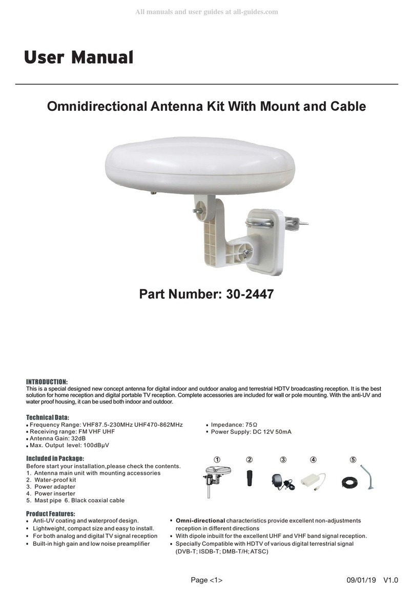
stellar labs 30-2447 User manual

stellar labs

stellar labs 30-2447 User manual

stellar labs 30-2370 User manual

stellar labs

stellar labs 30-2370 User manual

stellar labs 30-2447 User manual

stellar labs

stellar labs 30-2447 User manual

stellar labs 30-2476 User manual

stellar labs

stellar labs 30-2476 User manual

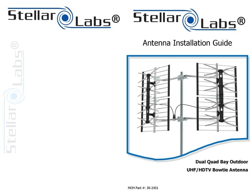
stellar labs 30-2431 User manual

stellar labs

stellar labs 30-2431 User manual

stellar labs 30-2440 User manual

stellar labs

stellar labs 30-2440 User manual

Popular Antenna manuals by other brands

Alf 9352-ALF-RICHT-ANT Assembly instructions

Alf

Alf 9352-ALF-RICHT-ANT Assembly instructions

Sematron Holkirk RM120 Operation & installation manual

Sematron

Sematron Holkirk RM120 Operation & installation manual

Novatel T2000 user manual

Novatel

Novatel T2000 user manual

Diamond Antenna SG-M510 Assembly

Diamond Antenna

Diamond Antenna SG-M510 Assembly

Philips SDW1850/17 Specifications

Philips

Philips SDW1850/17 Specifications

RF Elements Sector Carrier Class 5-20 manual

RF Elements

RF Elements Sector Carrier Class 5-20 manual

Kenwood SIRIUS CX-SR10 installation manual

Kenwood

Kenwood SIRIUS CX-SR10 installation manual

Norsat WAYFARER 1.2M KA-BAND user manual

Norsat

Norsat WAYFARER 1.2M KA-BAND user manual

Trango Systems AO900-3-P datasheet

Trango Systems

Trango Systems AO900-3-P datasheet

Ubiquiti AG-HP-2G20 quick start guide

Ubiquiti

Ubiquiti AG-HP-2G20 quick start guide

Feig Electronic ID ANT.U290/290-FCC installation manual

Feig Electronic

Feig Electronic ID ANT.U290/290-FCC installation manual

RCA ANT1400R quick start guide

RCA

RCA ANT1400R quick start guide

Hy-Gain GPG-1B instruction manual

Hy-Gain

Hy-Gain GPG-1B instruction manual

Panorama Antennas GPSG Series installation instructions

Panorama Antennas

Panorama Antennas GPSG Series installation instructions

SSI AVIOR Quick installation guide

SSI

SSI AVIOR Quick installation guide

Alpha Antenna HOA Buster user guide

Alpha Antenna

Alpha Antenna HOA Buster user guide

KVH Industries TrackPhone V7 installation guide

KVH Industries

KVH Industries TrackPhone V7 installation guide

Tonna F9FT Assembly instructions

Tonna

Tonna F9FT Assembly instructions

manuals.online logo
manuals.online logoBrands
  • About & Mission
  • Contact us
  • Privacy Policy
  • Terms and Conditions

Copyright 2025 Manuals.Online. All Rights Reserved.