Stellcase Lift and Lock Jules Platform with Standard Palm... User manual

Page 1 of 37
939504740 Rev E
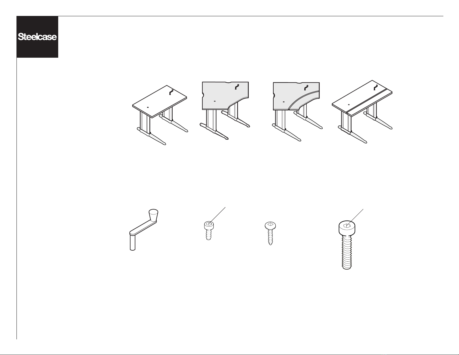
Crank Adjustable Units
Please identify the unit before selecting what section to follow
for assembly of product.
®
If you have a problem, question, or request, call
your local dealer, or Steelcase Line 1 at
888.STEELCASE (888.783.3522)
for immediate action by people who want to help you.
(Outside the U.S.A., Canada, Mexico, Puerto Rico,
and the U.S. Virgin Islands, call: 1.616.247.2500)
Or visit our website: www.steelcase.com
©2002 Steelcase Inc.
Grand Rapids, MI 49501
U.S.A.
Printed in U.S.A.
Extended or Hyperextended on Standard Corner Units
Straight or Corner Bilevel Unit
Straight, Corner, Corner Dual, or Straight Dual Unit
Right
Extension
Hyper
Extended
Left
Extension
Extended or Hyperextended on Bilevel Corner Units
Section A
(begins on page 2)
Section B
(begins on page 8)
Section C
(begins on page 13)
Section D
(begins on page 26)
Right
Extension
Hyper
Extended
Left
Extension
Page 2 of 37
939504740 Rev E
Worksurface
Screw
(Qty. 6)
Foot
Bolt
(Qty. 4)
5mm
Short
Mounting
Screw
(Qty. 8)
5mm
Crank
Handle
(Qty. 1)
Section A
Assembly instructions to
assemble the following units:

Page 3 of 37
939504740 Rev E
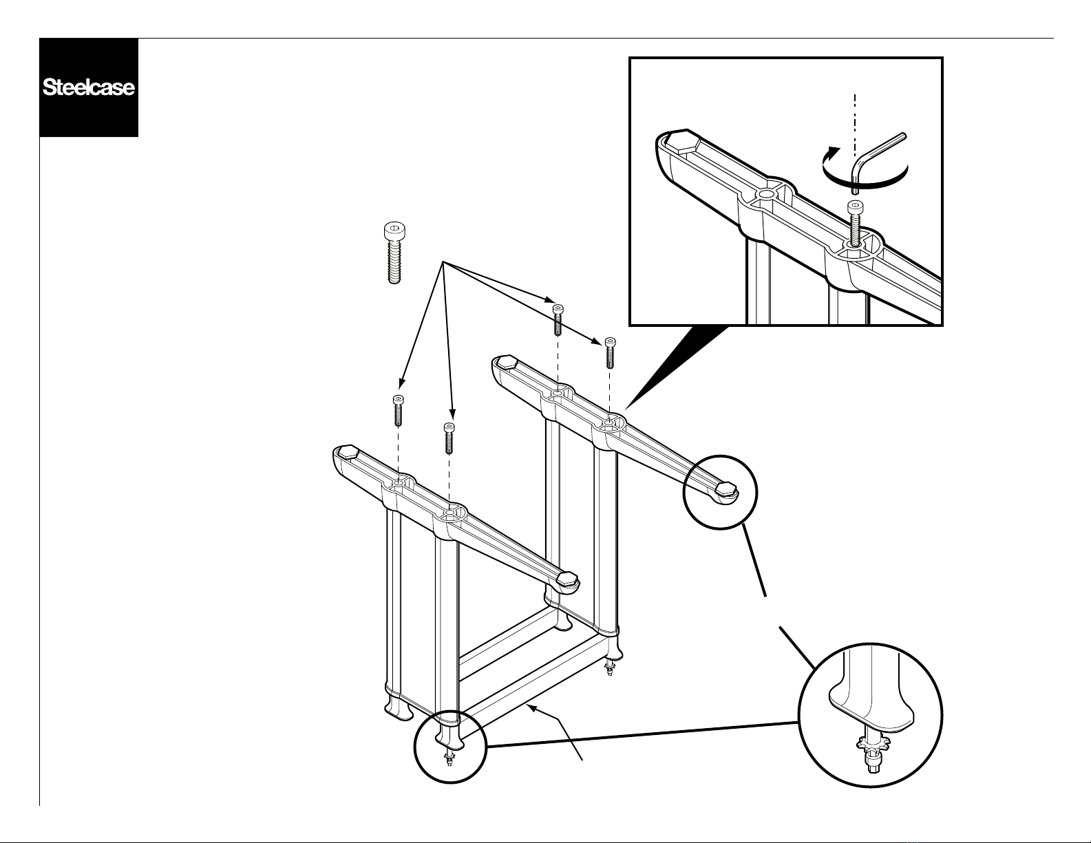
Foot Bolts
Front
1. Flip the base upside down and without
cutting the tie wraps, put the feet on.

Page 4 of 37
939504740 Rev E
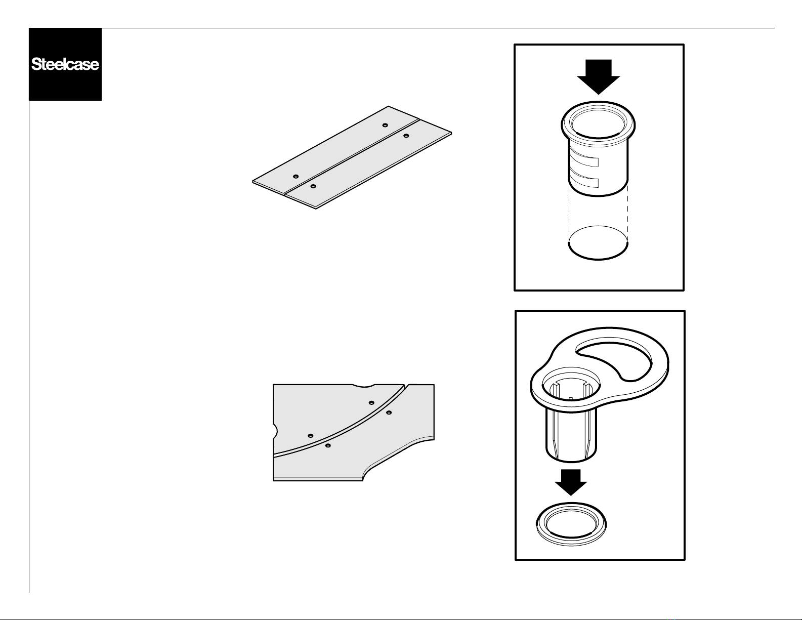
2.
3.
Straight Standard
Corner Standard
Corner Dual
Straight Dual
2. Install grommet (black) into laminated
side of worksurface.
3. Install guide (white) into grommet.

Page 5 of 37
939504740 Rev E
5.
(optional)
Gas Cylinder
Washer
Disk
Nut
4. Cut the tie wraps.
5. (Optional for STANDARD and
DUAL units only) Install the "nut",
"washer" and "disk" to the gas cylinder
(if not already installed). Place gas
cylinder as shown.
NOTE: DO NOT attempt to screw or
compress the gas cylinder into place.
CAUTION: Cylinder under compression!
To avoid possible injury when servicing
cylinder, raise worksurface to uppermost
position and remove worksurface prior to
removing mounting plate. This will minimize
compression in the cylinder and facilitate
its removal.

Page 6 of 37
939504740 Rev E
Worksurface Screws
Standard Corner
Straight Dual
Standard Straight
Rear
Rear
Front
Rear
Front
Front
6. Place the worksurface on a protected
surface. Attach mounting plates on
worksurface, at the screw locations shown,
after aligning the pilot holes.

Page 7 of 37
939504740 Rev E
Corner Standard
7. 8.
10.
Short Mounting Screws
Straight Standard
11.
NOTE: If unit is placed with a gas cylinder, adjust
the unit to full height of travel using crank handle.
7. Flip base upside down on a protected surface.
NOTE: If base has gas cylinder, be careful when
inverting the base.
8. Mount top to base with short mounting screws.
9. Flip unit to upright.
10. Remove Guides, retain for future assembly.
11. Test: Using the crank handle, adjust the unit
to different heights to ensure unit works properly.

Page 8 of 37
939504740 Rev E
Worksurface
Screw
(Qty. 16)
Foot
Bolt
(Qty. 4)
5mm
Short
Mounting
Screw
(Qty. 8)
5mm
Crank
Handle
(Qty. 1)
Section B
Assembly instructions to
assemble the following units:

Page 9 of 37
939504740 Rev E
Foot Bolts
Front
1. Flip the base upside down and without
cutting the tie wraps, put the feet on.
Page 10 of 37
939504740 Rev E
2.
3.
Straight Bilevel
Corner Bilevel
2. Install grommet (black) into laminated
side of worksurface.
3. Install guide (white) into grommet.

Page 11 of 37
939504740 Rev E
Worksurface
Screws
Bilevel Corner
Bilevel Straight
Rear
Front
Rear
Front
4. Place worksurface on a protected surface.
Attach mounting plates on worksurface.

Page 12 of 37
939504740 Rev E
Corner Bilevel
7.
6.
9.
Short Mounting Screws
Straight Bilevel
10.
5. Cut tie wraps.
6. Flip base upside down on a protected surface.
7. Mount top to base with short mounting screws.
8. Flip unit to upright.
9. Remove Guides, retain for future assembly.
10. Test: Using the crank handle, adjust both the
front and the rear surfaces of the unit to different
heights to ensure unit works properly.

Page 13 of 37
939504740 Rev E
Short
Mounting
Screw
(Qty. 12 max)
Worksurface
Screw
(Qty. 12 max)
Foot
Bolt
(Qty. 8 max)
5mm
5mm
Crank
Handle
(Qty. 1)
Strap
Screw
(Qty. 8 max)
Spacer
(Qty. 1)
Long
Mounting
Screw
(Qty. 4)
5mm
Tie Strap
(Qty. 2 max)
Connector Plate
(Qty. 2 max)
Connector
Plate
Screw
(Qty. 16 max)
Section C
Assembly instructions to
assemble the following units:
Page 14 of 37
939504740 Rev E
Foot Bolts
Front
1. Flip the base upside down and without
cutting the tie wraps, put the feet on.
NOTE: The large crossbar MUST
be in front for Standard Unit.
Page 15 of 37
939504740 Rev E
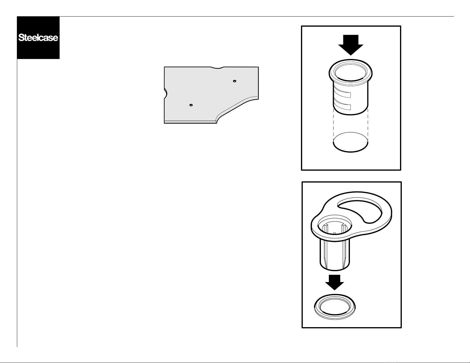
2.
3.
Corner Standard
2. Install grommet (black) into laminated
side of worksurface.
3. Install guide (white) into grommet.

Page 16 of 37
939504740 Rev E
5.
(optional)
Gas Cylinder
Washer
Disk
Nut
4. Cut the tie wraps.
5. (Optional for STANDARD and
DUAL units only) Install the "nut",
"washer" and "disk" to the gas cylinder
(if not already installed). Place gas
cylinder as shown.
NOTE: DO NOT attempt to screw or
compress the gas cylinder into place.
CAUTION: Cylinder under compression!
To avoid possible injury when servicing
cylinder, raise worksurface to uppermost
position and remove worksurface prior to
removing mounting plate. This will minimize
compression in the cylinder and facilitate
its removal.

Page 17 of 37
939504740 Rev E
Connector Plate
Connector Screw
Make sure the recessed holes are
facing away from the worksurface
at the holes that align with the
worksurface pilot holes.
6. Flip worksurface over on a protected surface.
Attach connector plates to corner worksurface.

Page 18 of 37
939504740 Rev E
8.
8.
7.
7. Loop chain over sprocket making sure that
the extensions must have the crossbars to the front.
NOTE: Do not pull the chain in any direction as
this could affect the height of the base.
8. Cut tie wraps.
NOTE: The front of the feet must be pointed
towards the inside of workstation.
9. FOR HYPER EXTENDED UNITS ONLY:
Repeat the above 2 steps to attach the other
extended link.

Page 19 of 37
939504740 Rev E
10.
Align
10. Adjust the extension links so as to align
the slots.

Page 20 of 37
939504740 Rev E
optional
necessary
optional
necessary
necessary
Gas
Cylinder
Washer
Disk
Nut
11. Install gas cylinder into open column of
extension bases.
NOTE: DO NOT attempt to screw in or compress
the gas cylinders into place.
OPTIONAL: If standard hyperextension unit has an
extra pair of gas cylinders (ordered separately),
place them now.
CAUTION: Cylinder under compression! To avoid
possible injury when servicing cylinder, raise
worksurface to uppermost position and remove
worksurface prior to removing mounting plate. This
will minimize compression in the cylinder and
facilitate its removal.
Other Stellcase Indoor Furnishing manuals

Popular Indoor Furnishing manuals by other brands


MAISONS DU MONDE
MAISONS DU MONDE GUAM 198367 manual

Kohler
Kohler MING K-77127T installation instructions

RTA
RTA TVM-060 Assembly instructions

Modus Furniture International
Modus Furniture International TOWNSEND STORAGE BED Assembly instructions

BLACK RED WHITE
BLACK RED WHITE KRISTOFF B191-LOZ120x200 Assembly

INOSIGN
INOSIGN VARADERO 3K1F1O UP 01261 Assembling Instruction