Stelpro SBB Series User manual

INSBBRE153RE1560815
For further information or to consult this guide online, please visit our website at www.stelpro.com
STELPRO DESIGN INC. | Saint-Bruno-de-Montarville | Québec | J3V 6L7
Before installing and operating this product, the user and/or installer must read, understand and follow these instructions and keep them handy for future
reference. If these instructions are not followed, the warranty will be considered null and void and the manufacturer deems no further responsibility for this product.
The following instructions must be adhered to in order to avoid personal and serious injuries, property damages and potentially fatal electric shocks.
Switch off the power at the circuit breaker/fuse before installing, repairing and cleaning the unit.
Make sure the unit is appropriate for the intended use (if needed, refer to the product catalog or a representative).
WARNING
COMPACT MULTIPURPOSE BASEBOARD | SBB SERIES
relay installation
RE153 - RE156 SERIES
JUNCTION BOX INSTALLATION AND WIRING - LEFT SIDE ONLY
1. Remove the front cover of the baseboard.
2. Position the relay (with the arrow pointing towards the top of the box) and
install with screws. Fig. 1
3. Insert the control wires supplied by the installer into the junction box
through one of the knock outs (KOE) and connect these wires with
the relay low voltage wires (blue) using appropriate wire nuts. For the
connections, refer to the wiring diagram.
4. Connect the wire coming from the wireway to a black wire of the relay
using with a wire nut. Fig. 2
5. Connect the other black relay wire to the line wire (L1) using an
appropriate wire nut. Connect the heating element wire to the second
line wire (L2/N).
6. Close the junction box and replace the cover, making sure the wires are
well placed inside the box.
FIG. 1 FIG. 2

INSBBRE153RE1560815
For further information or to consult this guide online, please visit our website at www.stelpro.com
STELPRO DESIGN INC. | Saint-Bruno-de-Montarville | Québec | J3V 6L7
Before installing and operating this product, the user and/or installer must read, understand and follow these instructions and keep them handy for future
reference. If these instructions are not followed, the warranty will be considered null and void and the manufacturer deems no further responsibility for this product.
The following instructions must be adhered to in order to avoid personal and serious injuries, property damages and potentially fatal electric shocks.
Switch off the power at the circuit breaker/fuse before installing, repairing and cleaning the unit.
Make sure the unit is appropriate for the intended use (if needed, refer to the product catalog or a representative).
WARNING
COMPACT MULTIPURPOSE BASEBOARD | SBB SERIES
relay installation
RE153 - RE156 SERIES
JUNCTION BOX INSTALLATION AND WIRING - RIGHT SIDE WITH CONNECTION ON LEFT SIDE
1. Remove the front cover of the baseboard.
2. Position the relay (with the arrow pointing towards the top of the box)
and install with screws. Fig. 1
3. Connect each blue wire to a white wire (TEW 105) and pass the wires
through the wireway. Fig. 2
4. Remove the wire nut (right side) and connect the red wire coming out
the wireway to one of the black wires of the relay. Fig. 3
5. Connect the element wire to the other black wire of the relay. Fig. 4
6. Place the separator (supplied with the kit), install with a screw in the left
junction box and insert the 2 control wires (white) into one of its holes.
Fig. 5
7. Insert the control wires supplied by the installer into the baseboard
electrical box through one of the knock outs (KOE). Connect the low
voltage wires with the relay wires, using the appropriate wire nut. For
the connections, refer to the diagram.
8. Remove the wire nut (left side) and connect the line wires (L1- L2/N).
9. Close the junction box and replace the cover, making sure the wires are
well placed inside the box.
FIG. 5
FIG. 1 FIG. 2
FIG. 4
FIG. 5
FIG. 3

INSSBBRE153T0815
For further information or to consult this guide online, please visit our website at www.stelpro.com
STELPRO DESIGN INC. | Saint-Bruno-de-Montarville | Québec | J3V 6L7
Before installing and operating this product, the user and/or installer must read, understand and follow these instructions and keep them handy for future
reference. If these instructions are not followed, the warranty will be considered null and void and the manufacturer deems no further responsibility for this product.
The following instructions must be adhered to in order to avoid personal and serious injuries, property damages and potentially fatal electric shocks.
Switch off the power at the circuit breaker/fuse before installing, repairing and cleaning the unit.
Make sure the unit is appropriate for the intended use (if needed, refer to the product catalog or a representative).
WARNING
COMPACT MULTIPURPOSE BASEBOARD | SBB SERIES
relay installation
RE153T SERIES
JUNCTION BOX INSTALLATION AND WIRING - RIGHT SIDE ONLY
1. Remove the front cover of the baseboard.
2. Position the relay (with the arrow pointing towards the top of the box)
and install with screws. FIG. 1
3. Insert the control wires supplied by the installer into the baseboard
electrical box through one of the knock outs (KOE). Connect the
low voltage wires with the relay wires, using a wire nut. Refer to the
diagram included with the relay for the different options.
4. Connect the blue relay wire to the wire that comes out of the wire way
(at the bottom of the unit) using an appropriate wire nut. FIG. 2
5. Connect the white relay wire (power side) to the element wire and a
line feed (L2/N) wire using an appropriate wire nut. FIG. 3
6. Connect the black relay wire (power side) to the other wire coming
from the line feed (L1) using an appropriate wire nut.
7. Close the junction box and replace the cover, making sure the wires
are well placed inside the box.
FIG. 1 FIG. 2
FIG. 3
L1
ALIMENTATION
GND
POWER SUPPLY
E
L2/N
Blanc /
White
Bleu /
Blue
Noir /
Black
A1
A2
G
Blanc
/
White
TH 24V
Noir /
Black
Rouge
/ Red
R
A

INSSBBRE153T0815
For further information or to consult this guide online, please visit our website at www.stelpro.com
STELPRO DESIGN INC. | Saint-Bruno-de-Montarville | Québec | J3V 6L7
Before installing and operating this product, the user and/or installer must read, understand and follow these instructions and keep them handy for future
reference. If these instructions are not followed, the warranty will be considered null and void and the manufacturer deems no further responsibility for this product.
The following instructions must be adhered to in order to avoid personal and serious injuries, property damages and potentially fatal electric shocks.
Switch off the power at the circuit breaker/fuse before installing, repairing and cleaning the unit.
Make sure the unit is appropriate for the intended use (if needed, refer to the product catalog or a representative).
WARNING
COMPACT MULTIPURPOSE BASEBOARD | SBB SERIES
relay installation
RE153T SERIES
JUNCTION BOX INSTALLATION AND WIRING - RIGHT SIDE ONLY WITH CONNECTION ON LEFT SIDE
1. Remove the front cover of the baseboard.
2. Position the relay (with the arrow pointing towards the top of the box) and
install with screws. FIG. 1
3. Connect the 3 control wires (red, black and white) with 3 appropriate
wires (TEW 105) and pass the 3 wires through the wireway to the left
junction box. FIG. 2
4. Remove the wire nut (Right junction box) and connect the element wire
to the blue wire of the relay, FIG. 3. Connect the red wire coming out the
wireway to the white wire of the relay, FIG. 4. Connect a black wire (TEW
105) to the black wire of the relay and then pass it through the wireway
to the right junction box. FIG. 5
5. Position the separator (supplied with the kit). Install it with a screw in the
left junction box and insert the 3 control wires into one of its holes. FIG. 6
6. Insert the control wires supplied by the installer into the baseboard
electrical box through one of the knock outs (KOE). Connect the low
voltage wires with the relay wires, using an appropriate wire nut. Refer
to the wiring diagram included with the relay for the different options.
7. Connect the black wire coming from the black wire of the relay (14 AWG)
to the line wire (L1) using an appropriate wire nut..
8. Connect the red wire coming from the white wire of the relay (14 AWG) to
the thermal protection wire and the line wire (L2/N) using an appropriate
wire nut..
9. Close the junction box and replace the cover, making sure the wires.
FIG. 1 FIG. 2
FIG. 3
FIG. 5
FIG. 4
FIG. 6

INSSBBR841AVEC0815
For further information or to consult this guide online, please visit our website at www.stelpro.com
STELPRO DESIGN INC. | Saint-Bruno-de-Montarville | Québec | J3V 6L7
Before installing and operating this product, the user and/or installer must read, understand and follow these instructions and keep them handy for future
reference. If these instructions are not followed, the warranty will be considered null and void and the manufacturer deems no further responsibility for this product.
The following instructions must be adhered to in order to avoid personal and serious injuries, property damages and potentially fatal electric shocks.
Switch off the power at the circuit breaker/fuse before installing, repairing and cleaning the unit.
Make sure the unit is appropriate for the intended use (if needed, refer to the product catalog or a representative).
WARNING
COMPACT MULTIPURPOSE BASEBOARD | SBB SERIES
relay installation
R841 SERIES WITH TRANSFORMER
JUNCTION BOX INSTALLATION AND WIRING - RIGHT SIDE ONLY
1. Remove the front cover of the baseboard.
2. Bend the tab on the transformer’s opposite side of the relay. FIG. 1
3. Position the relay in the top part of the right side junction box. FIG. 2
4. Connect the black relay wire (power side) to the line wire (L2/N) using
an appropriate wire nut.
5. Connect the blue/orange wire of the relay to the element wire and the
other line wire (L1). FIG. 3
6. Connect the red wire of the relay (Power side) to the red wire coming
out the wireway using an appropriate wire nut. FIG. 4
7. Insert the control wires supplied by the installer into the baseboard
junction box through one of the knock outs (KOE). Connect the low
voltage wires with the relay wires, using a wire nut. Please refer to
schematic for connection options.
8. Close the front cover, making sure the wires are well placed inside
the box.
FIG. 1 FIG. 2
FIG. 3 FIG. 4

INSSBBR841AVEC0815
For further information or to consult this guide online, please visit our website at www.stelpro.com
STELPRO DESIGN INC. | Saint-Bruno-de-Montarville | Québec | J3V 6L7
Before installing and operating this product, the user and/or installer must read, understand and follow these instructions and keep them handy for future
reference. If these instructions are not followed, the warranty will be considered null and void and the manufacturer deems no further responsibility for this product.
The following instructions must be adhered to in order to avoid personal and serious injuries, property damages and potentially fatal electric shocks.
Switch off the power at the circuit breaker/fuse before installing, repairing and cleaning the unit.
Make sure the unit is appropriate for the intended use (if needed, refer to the product catalog or a representative).
WARNING
COMPACT MULTIPURPOSE BASEBOARD | SBB SERIES
relay installation
R841 SERIES WITH TRANSFORMER
JUNCTION BOX INSTALLATION AND WIRING - RIGHT SIDE WITH CONNECTION ON LEFT SIDE
1. Remove the front cover of the baseboard.
2. Bend the tab on the transformer’s opposite side of the relay. FIG. 1
3. Position the relay in the top part of the right side junction box. FIG. 2
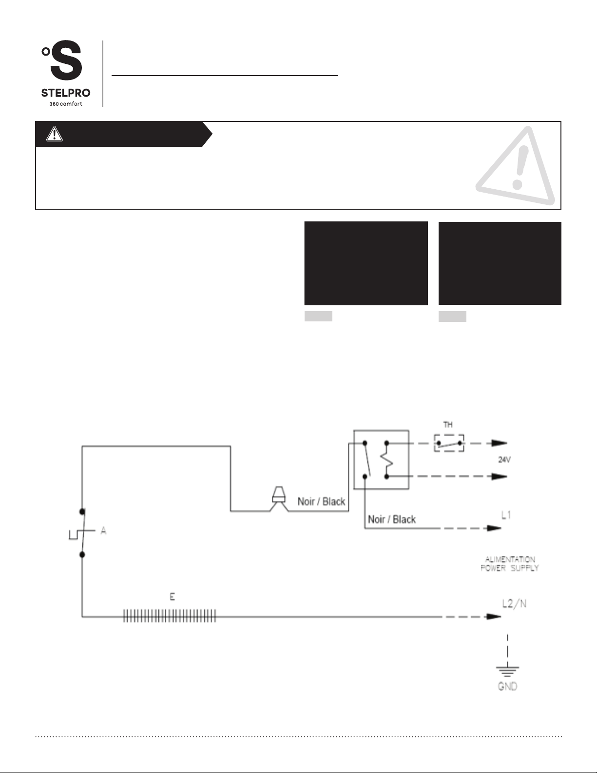
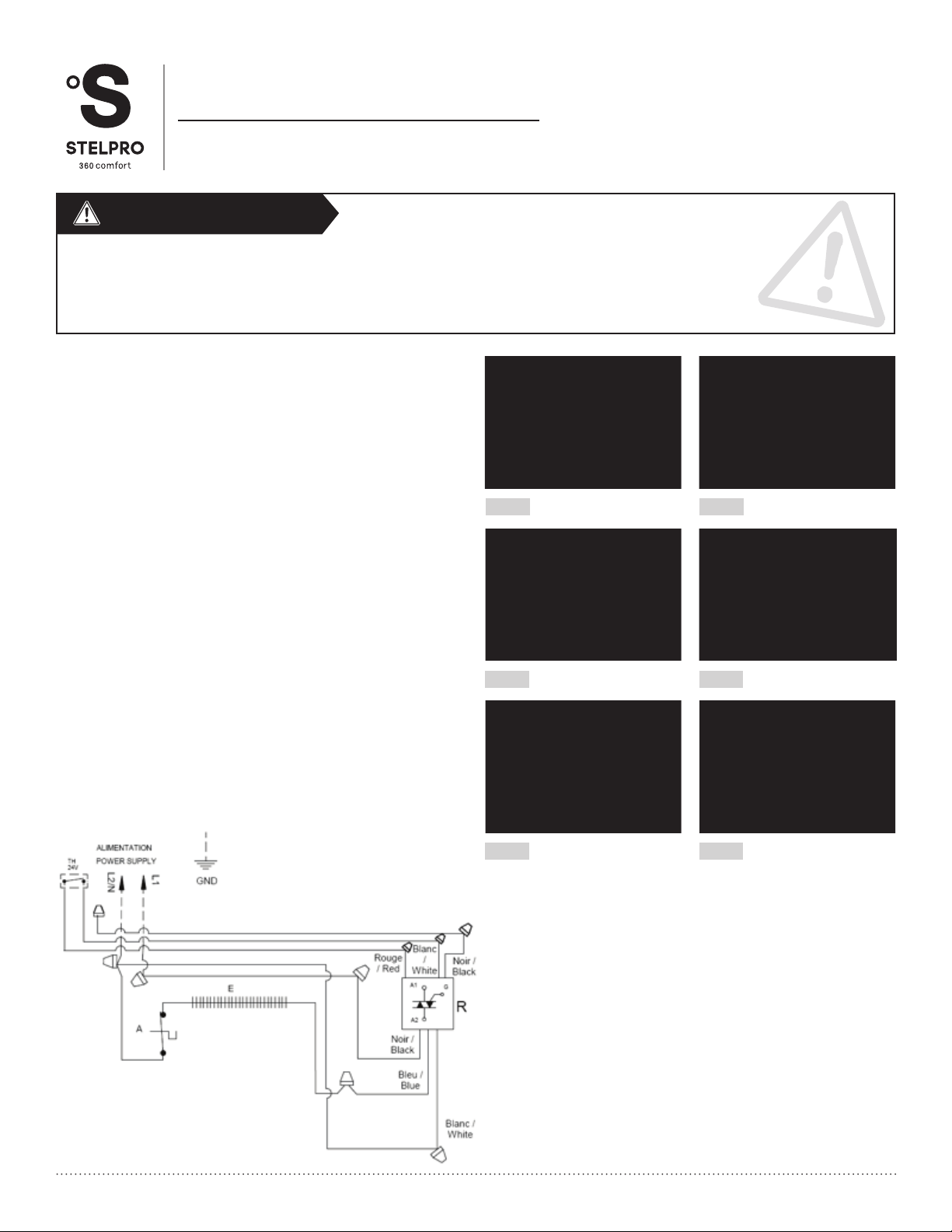
4. Connect the blue/orange wire of the relay to the heating element
wire and the wire coming out of the wireway with a wire nut. FIG. 3
5. Connect the black wire (Supplied by the installer) to the black wire
of the relay and pass it through the wireway to the left junction box.
FIG. 4
6. Connect the red wire of the relay (power wire) to a red wire (supplied
by the installer) and pass it through the wireway to the left junction
box, FIG. 5. Then, connect it to the thermal protection wire. FIG. 6
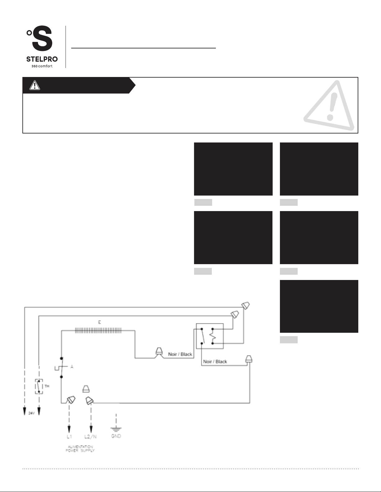
7. Connect the wires supplied by the installer (red and white) to the
control wires of the relay and pass them through the wireway to
the left junction box, FIG. 7. Place the voltage separator and install
with screws in the left junction box. Then pass the low voltage wires
through one of the holes in the voltage separator. FIG. 8
8. Insert the control wires supplied by the installer into the baseboard
junction box through one of the knock outs (KOE). Then insert
these wires into the second voltage separator hole. Connect the
low voltage wires with the relay wires, using a wire nut. Please refer
to schematic for connection options.
9. Connect the black relay wire (power side) to the line wire (L2/N)
using an appropriate wire nut and connect the red wire coming from
the heater element to the other line wire (L1).
10. Close the cover of the baseboard, making sure the wires are well
placed inside the box.
FIG. 1 FIG. 2
FIG. 4
FIG. 6
FIG. 8
FIG. 3
FIG. 5
FIG. 7

INSSBBR841SANS0815
For further information or to consult this guide online, please visit our website at www.stelpro.com
STELPRO DESIGN INC. | Saint-Bruno-de-Montarville | Québec | J3V 6L7
Before installing and operating this product, the user and/or installer must read, understand and follow these instructions and keep them handy for future
reference. If these instructions are not followed, the warranty will be considered null and void and the manufacturer deems no further responsibility for this product.
The following instructions must be adhered to in order to avoid personal and serious injuries, property damages and potentially fatal electric shocks.
Switch off the power at the circuit breaker/fuse before installing, repairing and cleaning the unit.
Make sure the unit is appropriate for the intended use (if needed, refer to the product catalog or a representative).
WARNING
COMPACT MULTIPURPOSE BASEBOARD | SBB SERIES
relay installation
R841 SERIES WITHOUT TRANSFORMER
JUNCTION BOX INSTALLATION AND WIRING - RIGHT SIDE ONLY
1. Remove the front cover of the baseboard.
2. Bend the shorter assembly metal tab. FIG. 1
3. Position the relay in the top of the junction box and install using a
screw. FIG. 2
4. Connect the red wire of the relay to the wire of the element using an
appropriate wire nut. FIG. 3
5. Connect the black relay wire (power side) to a line wire (L2/N) using
an appropriate wire nut.
6. Connect the red wire coming out the wireway to the other line wire (L1)
using an appropriate wire nut.
7. Insert the control wires supplied by the installer into the baseboard
junction box through one of the knock outs (KOE). Connect the low
voltage wires with the relay wires, using a wire nut. Please refer to
schematic for connection options.
8. Close the front cover of the baseboard, making sure the wires are well
placed inside the box.
FIG. 1 FIG. 2
FIG. 3

INSSBBR841SANS0815
For further information or to consult this guide online, please visit our website at www.stelpro.com
STELPRO DESIGN INC. | Saint-Bruno-de-Montarville | Québec | J3V 6L7
Before installing and operating this product, the user and/or installer must read, understand and follow these instructions and keep them handy for future
reference. If these instructions are not followed, the warranty will be considered null and void and the manufacturer deems no further responsibility for this product.
The following instructions must be adhered to in order to avoid personal and serious injuries, property damages and potentially fatal electric shocks.
Switch off the power at the circuit breaker/fuse before installing, repairing and cleaning the unit.
Make sure the unit is appropriate for the intended use (if needed, refer to the product catalog or a representative).
WARNING
COMPACT MULTIPURPOSE BASEBOARD | SBB SERIES
relay installation
R841 SERIES WITHOUT TRANSFORMER
JUNCTION BOX INSTALLATION AND WIRING - RIGHT SIDE WITH CONNECTION ON LEFT SIDE
1. Remove the front cover of the baseboard.
2. Bend the shorter assembly metal tab. FIG. 1
3. Position the relay in the top of the junction box and install with a
screw. FIG. 2
4. Connect the red wire of the relay to the wire of the element using an
appropriate wire nut. FIG. 3
5. Connect the black relay wire to the red wire coming from the
wireway using an appropriate wire nut. FIG. 4
6. Connect the 2 control wires of the relay with wires (red and white)
using an appropriate wire nut and pass the wires in the wireway to
the left side junction box. FIG. 5
7. Install the voltage separator in the left side junction box and pass the
two control wires through one of the holes in the separator. FIG. 6
8. Insert the control wires supplied by the installer into the baseboard
junction box through one of the knock outs (KOE). Then insert
these same wires into the voltage separator hole. Connect the low
voltage wires with the relay wires, using the appropriate wire nut.
Please refer to schematic for connection options.
9. Connect the black wire of the thermal protection to the line wire (L1)
and the wire coming from the wireway to the line wire (L2/N).
10. Close the baseboard cover, making sure the wires are well placed
inside the box.
FIG. 1 FIG. 2
FIG. 4
FIG. 6
FIG. 3
FIG. 5
This manual suits for next models
2
Table of contents
Other Stelpro Relay manuals