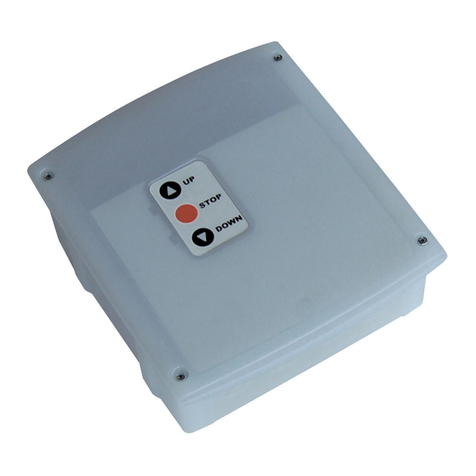
Stenner Pumps PCM series Manual

TO BE INSTALLED AND MAINTAINED BY PROPERLY TRAINED
PROFESSIONAL INSTALLER ONLY. READ MANUAL & LABELS
FOR ALL SAFETY INFORMATION & INSTRUCTIONS.
WARNING
PCM SERIES PUMP CONTROL MODULE
INSTALLATION AND MAINTENANCE MANUAL
PERISTALTIC METERING PUMPS SINCE 1957

www.stenner.com
2
TABLE OF CONTENTS
WARRANTY AND SERVICE POLICY .................................. 3
SAFETY INFORMATION .............................................. 4-5
SPECIFICATIONS ......................................................... 6
SIZING ................................................................. 7-11
INSTALLATION ...................................................... 12-13
TROUBLESHOOTING ................................................... 14
PCM OPERATING RANGE CONVERSION ......................... 15
IMPCM 0616a

USA and Canada 800.683.2378, International 904.641.1666
WARRANTY AND CUSTOMER SERVICE
LIMITED WARRANTY
Stenner Pump Company will for a period of one (1) year from the date of purchase (proof of
purchase required) repair or replace – at our option – all defective parts. Stenner Pump Company
is not responsible for any removal or installation costs. Stenner Pump Company will incur
shipping costs for warranty products shipped from our factory in Jacksonville, Florida. Any
tampering with major components, chemical damage, faulty wiring, weather conditions, power
surges, or products not used with reasonable care and maintained in accordance with the
instructions will void the warranty. Stenner Pump Company limits its liability solely to the cost
of the original product. We make no other warranty expressed or implied.
RETURNS
Stenner offers a 30-day return policy. Except as otherwise provided, no material will be
accepted for return after 30 days from purchase. To return merchandise at any time, call
Stenner at 800-683-2378 for a Return Merchandise Authorization (RMA) number. A 15%
re-stocking fee will be applied. Include a copy of your invoice or packing slip with your return.
DAMAGED OR LOST SHIPMENTS
All shipments: Check your order immediately upon arrival. All damage must be noted on
the delivery receipt. Call Stenner Customer Service at 800-683-2378 for all shortages and
damages within seven (7) days of receipt.
DISCLAIMER
The information contained in this manual is not intended for specific application purposes.
Stenner Pump Company reserves the right to make changes to prices, products, and
specifications at any time without prior notice.
3

www.stenner.com
4
SAFETY INFORMATION
Warns about hazards that CAN cause death, serious
personal injury, or property damage if ignored.
ELECTRIC SHOCK HAZARD
This information contained in this manual is for reference only.
Prior to beginning any water treatment regimen, always consult with a water
treatment professional and adhere to the information contained in the chemical
manufacturer’s Material Safety Data Sheet.
Equipment is supplied with grounding power cord and attached
plug. To reduce risk of electrical shock, connect only to a properly grounded,
grounding type receptacle. Install only on a circuit protected by a Ground-Fault
Circuit-Interrupter (GFCI).
DO NOT alter the power cord or plug end.
DO NOT use receptacle adapters.
DO NOT use PCM with a damaged or altered power cord or plug. Contact the factory
for repair.
HAZARDOUS VOLTAGE
DISCONNECT power cord before removing cover for service. Electrical service by
trained personnel only.
EXPLOSION HAZARD
This equipment IS NOT explosion proof. DO NOT install or operate in an
explosive environment.
RISK OF FIRE HAZARD
DO NOT install or operate on any flammable surface.
Warns about hazards that WILL or CAN cause minor personal
injury or property damage if ignored.
Final settings on Stenner Metering Pumps or Pump Control
Modules must be determined through analytical testing of the treated water. The formulas
contained herein are intended solely as a guide to be used to assist in the proper
application of Stenner Pumps. The Stenner Pump Company makes no guarantee as to the
accuracy of the information contained herein. User assumes all risk and liability from use
of the information contained in this manual.

USA and Canada 800.683.2378, International 904.641.1666
SAFETY INFORMATION continued
5
NOTICE: Indicates special instructions or general mandatory action.
DO read all product manuals for proper safety and complete operation instructions.
DO NOT attempt installation or service prior to reading and understanding all safety
hazards. This equipment is designed for installation and service by trained personnel.
DO install PCM so that it is in compliance with all national and local codes.
DO use all required personal protective equipment when working on or near
chemical metering pumps.
Before installing or servicing the PCM, read the PCM manual for all safety
information and complete instructions. The PCM is designed for installation and
service by properly trained personnel.
Installation and product must adhere to all regulatory and compliance codes
applicable to the area.
This is the safety alert symbol. When displayed in this manual or on the
equipment, look for one of the following signal words alerting you to the
potential for personal injury or property damage.
PCM INTENDED FOR INDOOR USE.
Electrical installation should adhere to all national and local codes. Consult a licensed
professional for assistance with proper electrical installation.
This appliance is not intended for use by persons (including children) with reduced
physical, sensory or mental capabilities, or lack of experience and knowledge, unless
they have been given supervision or instruction to concerning use of the appliance by
a person responsible for their safety.

6
SPECIFICATIONS
www.stenner.com
HOUSING
Polycarbonate
TIMER
Microcontroller with triac output
TURNDOWN RATIO
10:1
INPUT SIGNAL
Non-voltage dry contact water meter
RESET TIME
Immediate
MINIMUM SIGNAL DURATION
10 milliseconds
INPUT ELECTRICAL
120V 60Hz
MAXIMUM LOAD
1.8 A @ 120V 60Hz/216 V-A
NO LOAD CURRENT
0.45mA AC maximum
SHIPPING WEIGHT
2 lbs (0.9 kg)
BOX DIMENSIONS
9 x 8 x 7 in. (23 x 20 x 18 cm)
Top
Front
Side
3.6"
5.9"
2.2"
3.6"
5.4"
2.2"

USA and Canada 800.683.2378, International 904.641.1666
SIZING
7
PRE-SIZING REQUIREMENTS
• Maximum system flow rate or well pump flow rate in gallons per minute (gpm) or
liters per minute (lpm)
• Dosage in parts per million (ppm)
• Solution strength in parts per million (ppm)
• Water meter contacts per gallon (cpg or ppg) or per liter (cpl or ppl)
• Stenner fixed output metering pump
Key
min. minute
sec. second
ppm parts per million
cpg contacts per gallon
ppg pulse per gallon
gpm gallons per minute
gpd gallons per day
spg seconds per gallon
cpl contacts per liter
ppl pulse per liter
lpm liters per minute
lpd liters per day
spl seconds per liter

www.stenner.com
8
SIZING IN GALLONS
Pre-Programming Requirements
A. Determine the Maximum System Flow Rate or Well Pump Flow Rate in Gallons
per Minute.
If well pump output is unknown, refer to example below:
Calculate well pump output rate (gpm).
Determine the output rate by opening a faucet until the well pump turns on.
Immediately turn off the faucet and time how long the well pump runs. Next,
measure the volume of water drawn from the faucet until the well pump turns
on again.
Volume of water until the pump turns on (gallon) =Well Pump Output Rate
How long the pump runs (min.) (gpm)
B. Determine Solution Strength Percentage and the Dosage Requirement in Parts
per Million.
If dosage is unknown, refer to example below:
Calculate required dosage (ppm).
Refer to Oxidation Rates below. Estimate dosage and include the ppm of
required residual.
10 gallons = 5 gpm
2 minutes
Example: After drawing 10 gallons of water,
the well pump took 2 minutes to fill the
pressure tank and stop.
Common Chemical Solution Strengths in ppm
Name % ppm
Sodium Hypochlorite 5.25 52,500
6.125 61,250
12.5 125,000
Potassium Permanganate Dissolved at 1/4 lb per gallon 3 30,000
Hydrogen Peroxide 7 70,000
Polyphosphate Dissolved at 1 lb per 10 gallons 1.2 12,000
Oxidation Rates
For each ppm of Iron Manganese Hydrogen Sulfide
Required ppm of Chlorine 12 3
Required ppm of Hydrogen Peroxide 0.5 1 1.5
2 ppm iron x 1 ppm chlorine = 2
4 ppm hydrogen sulfide x 3 ppm chlorine = 12
1 ppm chlorine residual = 1
Total 2 + 12 + 1 = 15 ppm
Example: To treat a water supply containing
2 ppm iron and 4 ppm hydrogen sulfide
with a chlorine residual of 1 ppm, a dosage
15 ppm of chlorine is required.

USA and Canada 800.683.2378, International 904.641.1666 9
SIZING IN GALLONS
Pre-Programming Requirements continued
C. Calculate Metering Pump Output Requirement in Gallons per Day.
Maximum System Flow Rate (gpm) x Dosage (ppm) x 1440 =Metering Pump
Output Requirement
Solution Strength ppm*
(gpd)
*Solution Strength % x 10,000 = Solution Strength ppm
D. Reference the chart below to confirm the selected pump’s maximum output slightly
exceeds the pump output requirement calculated in C.
Stenner Fixed Output Pumps (26-100 psi)
Model Pump Tube Maximum Output (gpd)
45MPHP2 #1 3
45MPHP10 #2 10
45MPHP22 #7 22
85MPHP5 #1 5
85MPHP17 #2 17
85MPHP40 #7 40

www.stenner.com
10
SIZING IN GALLONS continued
1. Calculate the Available Dose Time in Seconds.
The Available Dose Time is the minimum time interval between water meter contact
closures. Each closure sends an input signal to the PCM.
a. 60 =
Maximum System Flow Rate (gpm) Maximum System Flow Rate (spg)
b. Maximum System Flow Rate (spg)
Water Meter’s contacts per gallon (cpg)* =Available Dose Time (sec.)
*Refer to the water meter model number to confirm the contact rate (cpg).
2. Calculate the PCM Operating Time in Seconds.
Calculate the PCM Operating Time based on pump selection in D, solution and dosage
in B and use the formula below.
Pump Output Requirement (gpd) x Available Dose Time (sec.) =PCM Operating
Pump’s Maximum Output (gpd) Time (sec.)
PCM OPERATING TIME EXCEEDING AVAILABLE DOSE TIME
MAY LEAD TO DOSING ERRORS. To reduce PCM Operating Time, select a pump with
a higher output or use stronger solution strength.

USA and Canada 800.683.2378, International 904.641.1666 11
SIZING IN GALLONS continued
50 60
70
80
90
100%
40
30
3. Select PCM Model based on PCM Operating Time determined in #2, refer to the
chart below.
PCM OPERATING TIME EXCEEDING AVAILABLE DOSE TIME
MAY LEAD TO DOSING ERRORS. To reduce PCM Operating Time, select a pump
with a higher output or use stronger solution strength.
4. Determine PCM Setting Percentage.
PCM Operating Time (sec.) x 100 = PCM Setting Percentage (%)
Maximum PCM Operating Time (sec.)**
** Value can only be 1, 5, 10 or 20
Turn the PCM knob to adjust to the percentage setting calculated. Use the locking
screw located on the PCM knob to secure it.
PCM Models
Model Operating Range*(seconds)
PCM1 0.1 to 1.0
PCM5 0.5 to 5.0
PCM10 1.0 to 10.0
PCM20 2.0 to 20.0
*Factory preset

www.stenner.com
12
INSTALLATION
Mount PCM in a dry location to avoid water intrusion and damage.
1. Position the PCM within 6 feet of the Stenner fixed output metering pump and mount
to a suitable surface using adequate fasteners through the mounting holes.
Check supply voltage prior to connecting power cord to prevent damage. The use
of a GFCI circuit is recommended.
2. Uncoil the input signal cable and remove approximately 2 inches of the outer
cable jacket.
DO NOT connect PCM input signal cord to any AC voltage supply.
DO NOT connect PCM input signal cord to any hall effect, 4-20mA or voltage
carrying signal source.
3. Strip the ends of the two wires within the cable approximately one-half inch.
Use PCM only with a dry contact, reed switch style water meter.
4. Attach the two wires to the contact output water meter or relay switch.
5. Adjust the knob to the desired on-time duration. Refer to the “Sizing” in this manual
for assistance.
If using an adjustable metering pump, it is recommended that the pump be set
at 100%.
6. With necessary suction, discharge and point of injection connections secured,
prime the pump by plugging it into a 120V receptacle and turning on the power
switch.
7. Unplug the fixed output metering pump’s power cord from receptacle and plug into
the PCM’s receptacle.
8. Plug the PCM power cord into a properly grounded, 120V receptacle.

INSTALLATION DIAGRAM
USA and Canada 800.683.2378, International 904.641.1666
Grounded Power Outlet;
protected by Ground-Fault
Circuit-Interrupter (GFCI);
120V shown
PCM
Point of
Injection
Shut-Off Valve
Water Meter
PCM Power Cord
Stenner
Fixed Output
Metering Pump
Spill Recovery Tube
Solution Tank
Metering Pump Power Cord
Water Meter
Output Cable
Connection
PCM Input
Signal Cable
13

www.stenner.com
14
TROUBLESHOOTING
LACK OF INPUT SUPPLY VOLTAGE (120V)
Plug the fixed output chemical metering pump directly into the 120V receptacle into which
the PCM was originally plugged. This will bypass the PCM. If the pump does not run, the
power source or pump is defective. If the metering pump operates, proceed to LACK OF
PROPER INPUT SIGNAL.
LACK OF PROPER INPUT SIGNAL
Plug the metering pump into the PCM and the PCM into the receptacle tested in Step I.
Remove the PCM input signal cable from the water meter or relay and touch the two wires
together. The pump should operate for the pre-determined run time setting and then stop.
• If the metering pump runs, the failure is in the water meter contacts.
• If the metering pump does not run, the failure is in the PCM.
• Contact the factory for information on service and repair.

PCM OPERATING RANGE CONVERSION
A B
USA and Canada 800.683.2378, International 904.641.1666 15
HAZARDOUS VOLTAGE
DISCONNECT power cord before removing cover for service. Electrical service by
trained personnel only.
The PCM operating range is factory set according to the specific model. The operating
range can be changed to convert a PCM to any of four available operating ranges without
purchasing another model.
The operating range is converted by changing the position of the jumpers on the printed
circuit board located under the PCM’s cover. Illustration A. The PCM is equipped with two
jumpers that are positioned over the pins labeled 3, 2, 1. Illustration B.
To change the time range:
1. Unplug the PCM power cord from the input power supply.
2. Remove the cover and reposition the jumpers to correspond with the desired
operating range. Refer to Interchangeable Operating Range Settings below.
3. Replace the PCM cover.
4. IMPORTANT! Update the PCM data label to represent the converted model and
operating range for accurate sizing.
13 2
Jumpers
Pins
INTERCHANGEABLE OPERATING RANGE SETTINGS
0.1–1 second
(Jumper 2 & 1)
2–20 seconds
(Jumper 3 & 2, 2 & 1)
1–10 seconds
(Jumper 3)
0.5–5 seconds
(Jumper 3 & 2)
2121
3123 3 12
3
Location of
the jumpers

STENNER PUMP COMPANY
3174 DeSalvo Road
Jacksonville, Florida 32246 USA
Phone: 904.641.1666
US Toll Free: 800.683.2378
Fax: 904.642.1012
sales@stenner.com
www.stenner.com
Hours of Operation (EST):
Mon.–Thu. 7:30 am–5:30 pm
Fri. 7:00 am–5:30 pm
Assembled in the USA
© Stenner Pump Company
All Rights Reserved
IMPCM 0616a

INSTALACION Y MANTENIMIENTO DEBEN SER REALIZADOS POR
PROFESIONALES DEBIDAMENTE ENTRENADOS. LEA EL MANUAL Y
LAS ETIQUETAS PARA OBTENER LAS INSTRUCCIONES Y LA
INFORMACION DE SEGURIDAD.
ADVERTENCIA
MODULO DE CONTROL DE DOSIFICADORES SERIE PCM
MANUAL DE INSTALACION Y MANTENIMIENTO
DOSIFICADORES PERISTALTICOS DESDE 1957

www.stenner.com
2
TABLA DE CONTENIDO
GARANTIA Y NORMAS DE SERVICIO ............................... 3
INFORMACION DE SEGURIDAD................................... 4-5
ESPECIFICACIONES..................................................... 6
DIMENSIONAMIENTO .............................................. 7-11
INSTALACION ....................................................... 12-13
GUIA DE REPARACIONES............................................ 14
CONVERSION DE INTERVALOS DE FUNCIONAMIENTO ...... 15
IMPCM 0616a

EE. UU. y Canadá +1.800.683.2378, Internacional +1.904.641.1666
GARANTIA Y NORMAS DE SERVICIO
GARANTIA LIMITADA
Por un período de un (1) año de la fecha de compra (se exige comprobante de compra),
Stenner Pump Company reparará o reemplazará, a su criterio, todas las piezas
defectuosas. Stenner Pump Company no es responsable de los costos de retiro o
instalación. Stenner Pump Company pagará los costos de envío de los productos en
garantía desde nuestra fábrica en Jacksonville, Florida. Toda manipulación de los
componentes principales, daño causado por productos químicos, cables defectuosos,
condiciones climáticas, sobrecargas de energía o productos que no se utilicen y
mantengan con debido cuidado de acuerdo con las instrucciones, anularán la garantía.
Stenner Pump Company limita su responsabilidad exclusivamente al costo del producto
original. No otorgamos ninguna otra garantía, expresa o implícita.
DEVOLUCIONES
Stenner ofrece una política de devolución de 30 días. Salvo que se exprese lo contrario,
ningún material se aceptará para devolución después de 30 días de su compra. Para
devolver un producto en cualquier momento, llame a Stenner al +1.904.641.1666 y pida
un número de autorización de devoluciones (RMA, por sus siglas en inglés). Se aplicará
una tarifa de reabastecimiento de 15%. Incluya una copia de su factura o lista de
empaque con su devolución.
DAÑO O PERDIDA DE ENVIOS
Todos los envíos: Revise su pedido de inmediato al recibirlo. Todos los daños se deben
anotar en el comprobante de entrega. Llame a Servicio al Cliente de Stenner al
+1.904.641.1666 para informar de envíos dañados e incompletos en un plazo de siete
(7) días de recibirlos.
CLAUSULA DE EXENCION DE RESPONSABILIDAD
La información que contiene este manual no está prevista para fines de aplicaciones
específicas. Stenner Pump Company se reserva el derecho de efectuar cambios en los
precios, productos y especificaciones, en cualquier momento y sin previo aviso.
3

www.stenner.com
4
INFORMACION DE SEGURIDAD
Advierte sobre peligros que PUEDEN causar la muerte,
lesiones personales graves o daño a la propiedad si se le ignora.
PELIGRO DE DESCARGA ELECTRICA
La información que contiene este manual solo está prevista como
referencia. Antes de iniciar cualquier régimen de tratamiento de agua, consulte
siempre a un profesional para tratamientos de agua y cumpla siempre con la
información contenida en la Hoja de datos de seguridad de materiales de fabricante
de productos químicos.
El equipo incluye un cable de alimentación con conexión a tierra
y un enchufe. Para reducir el riesgo de descarga eléctrica, conecte sólo a un
receptáculo correctamente conectado a tierra. Instale sólo en un circuito protegido
por un Interruptor accionado por corriente de pérdida a tierra (GFCI).
NO altere el cable de alimentación o extremo macho.
NO use adaptadores de receptáculos.
NO use el PCM con un cable de alimentación o enchufe dañado o alterado.
Comuníquese con la fábrica para su reparación.
VOLTAJE PELIGROSO
DESCONECTE el cable de alimentación antes de sacar la tapa para realizar servicio.
Sólo personal entrenado debe realizar reparaciones.
PELIGRO DE EXPLOSION
Este equipo NO es a prueba de explosiones. NO instale o haga funcionar en un
entorno explosivo.
RIESGO DE INCENDIO
NO instale o haga funcionar en una superficie inflamable.
Advierte sobre peligros que PUEDEN causar o que CAUSARAN
lesiones personales menores o daño a la propiedad si se les ignora.
Los parámetros finales en los dosificadores Stenner o en los
módulos de control del dosificador se deben determinar mediante pruebas analíticas en
el agua tratada. Las fórmulas contenidas en el presente solo pretenden ser guías para
ayudar en la correcta aplicación de los dosificadores Stenner. Stenner Pump Company no
garantiza la exactitud de la información contenida en el presente. El usuario asume
cualquier riesgo o responsabilidad por el uso de la información contenida en este manual.
Table of contents
Languages:
Popular Control Unit manuals by other brands

Belden
Belden GRASS VALLEY ADX-1901 Guide to installation and operation

IFM
IFM CR2033 Device manual
herdstar
herdstar Bintrac Installation and operation manual
Giacomini
Giacomini R453HY011 Instruction

Pentair
Pentair Anderson Greenwood 93 Series Installation and maintenance instructions

ZURN
ZURN WILKINS 450 instructions
