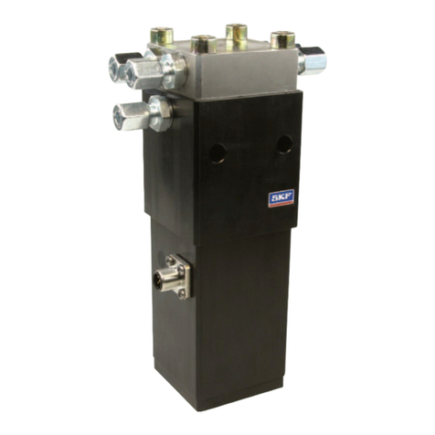
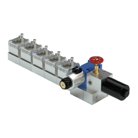
SKF DCV5-4+924 User manual

DCV5-4+924 5/4 way valve for grease
24V DC
Operating Manual
Version 02


Contents Page 3
EN
Imprint
These operating instructions are part of the 5/4
way valve DCV5-4+924
These operating instructions were compiled as
per the applicable standards and regulations for
technical documentation as well as in
accordance with the VDI 4500 and the
EN 292.
© Copyright
SKF LUBRICATION SYSTEMS GERMANY AG
reserves the right to make changes to adapt to
technical improvement. Reprinting or copying
even of parts of this operating manual requires
the permission of SKF LUBRICATION SYSTEMS
GERMANY AG.
Editor
Dipl.-Ing. S. Waschki
Dipl.-Ing. Dieter Schönherr
Contents
1Information regarding the EC
declaration of conformity and
installation ...................................... 4
2Sicherheitshinweise ....................... 5
2.1 General Information............................... 5
2.2 Intended Use ......................................... 5
2.3 Authorised personnel ............................ 5
2.4 Installation work..................................... 6
2.5 Danger caused by electricity................. 6
2.6 Danger caused by system pressure..... 6
2.7 Permitted lubricants............................... 6
2.8 Endangering the environment with
lubricants ............................................... 6
2.9 Packaging, transport and storage ........ 6
2.10 Disclaimer .............................................. 6
3Design and Function....................... 7
3.1 Function ................................................. 7
3.2 Design .................................................... 8
4Installation...................................... 9
4.1 Setup...................................................... 9
4.2 Connecting the lubrication lines ........... 9
4.3 Electrical Connection ............................ 9
5Maintenance and Repair .............. 10
6Service .......................................... 10
7Specifications ............................... 11

Information regarding the EC declaration of conformity and installation Page 4
EN
For the product designated below:
5/4 way valve
Series: DCV5-4+924 for 24V DC
we herewith certify that it conforms to the
pertinent safety requirements set forth in the
following Council Directive(s) for the
harmonisation of the laws of the Member
States...
Electromagnetic compatibility 2004/108/EG
2006/28/EG (vehicles)
98/37/EG (machines)
97/23/EG (pressure
devices).
Notes
(a) This declaration certifies the conformity with
the directives listed, but does not entail an
express assurance of properties.
(b) The safety instructions in the documentation
accompanying the product must be
observed.
(c) Taking into operation of the certified
products is not allowed until evidence has
been provided that the machinery, vehicle
or similar item, into which the product is
integrated, conforms to the regulations and
requirements set forth by the applicable
directives.
(d) The operation of the products on non-
standard line voltage as well as non-
adherence to the installation instructions
can affect the EMC properties and electrical
safety.
We further declare that the above mentioned
product:
is an incomplete machine according to the
machine directive 98/37/EG Appendix II 1B.
Taking into service is not admissible until
evidence has been provided that the machine
in which this part is installed or to which this
part is connected, conforms to the regulations
set forth in the EC directive 2006/42/EC. Prior
to its installation into a complete machine, the
instructions contained in the installation
declaration and the installation instructions
must be observed.
with reference to the EC directive 97/23/EC
concerning apparatus subjected to
pressure this product must only be used as
intended and according to the notes in the
documentation. Especially observe the
following:
SKF products must not be used in
conjunction with fluids, group I (hazardous
fluids), according to the definition of article 2
paragraph 2 of the Directive 67/548/EEC dtd.
27th June, 1967; and are not approved for
application with such.
None of the products manufactured by SKF
are approved for application in connection
with gases, liquefied gases, gases dissolved
under pressure, steams or fluids that will
reach a steam pressure of more than 0.5 bar
above the normal atmospheric pressure
(1013 mbar) in the admissible application
temperature range.
When used as intended, the products
supplied by us do not reach the limit values
listed in the Article 3 par. 1, sections 1.1 to 1.3
and par. 2 of the directive 97/23/EC.
Therefore they do not come under the
requirements set forth in annex I of that
directive. They are not labelled with the CE
mark with reference to the directive 97/23/EC.
They are classified by us to come under
Article 3 par. 3 of the directive.
SKF products must only be used as intended.
Use or taking into operation of the products in
areas with potentially explosive atmospheres
according to the ATEX directive 94/9/EC is
not allowed, regardless of whether these
entail gaseous atmospheres or dusty
atmospheres.
If required, you may request the declaration of
conformity or manufacturer´s declaration for
this product from our central contact address.
1 Information regarding the EC declaration of conformity and installation
Sicherheitshinweise Page 5
EN
2 Sicherheitshinweise
2.1 General Information
The components described here were
manufactured in accordance with the applicable
regulations of today's technology and the work
safety and accident prevention guidelines.
However, even if it is adhered to, dangerous
situations may arise that could cause injuries to
the operator or damages to property. Therefore,
the components should only be used if they are
in flawless technical condition and while
observing the operating instructions. Especially
errors that could affect safety must be resolved
without delay.
Text marked with this symbol
indicates special hazards or
important actions and
procedures.
2.2 Intended Use
The SKF 5/4 way valve DCV5-4+924 is intended
for use in progressive distribution lubrication
systems with multiple lubrication circuits
running on SKF-approved lubricants.
The information regarding the operating
conditions in Chapter 7 – SPECIFICATIONS
(system pressure, temperature, operating
voltage, etc.) must be adhered to.
The 5/4 way valve DCV5-4+924
may only be used in lubrication
systems with integrated
pressure limiting valves.
Other or use beyond this purpose is considered
unintended.
2.3 Authorised personnel
The components described in these instructions
may only be installed, operated, maintained and
repaired by qualified personnel. Qualified
personnel has been trained, instructed and
specifically ordered by the owner to perform the
work. Due to their training and experience,
these persons are familiar with the applicable
standards, regulations, accident prevention
rules and operating conditions. They are
authorised to perform the respective tasks and
capable of identifying and avoiding possible
hazards.
The definition of what is a trained specialist and
the prohibition of use by unqualified personnel
are set forth in DIN VED 0105 or IEC 364.

Sicherheitshinweise Page 6
EN
2.4 Installation work
All installation work on vehicles and machines is
subject to the regional accident prevention
regulations as well as the applicable operating
and maintenance guidelines. The installation
instructions and installation declaration included

with the product must be adhered to.
2.5 Danger caused by electricity
The electrical connection of the components
may only be performed by trained skilled
personnel while observing the local connection
guidelines and regulations (e.g. DIN, VDE). If
devices are improperly connected, substantial
material and personal damage may be the
consequence.
2.6 Danger caused by system
pressure
The lubrication systems, which include these
components can be subject to hydraulic
pressure. Therefore, they must be
depressurised prior to performing extension
work, changes, repairs etc.
2.7 Permitted lubricants
You can request a current list of SKF-approved
lubricants through your field employee or the
manufacturing sites.
Please also observe the
authorised lubricant lists issued
by the machine or vehicle
manufacturer.
2.8 Endangering the environment
with lubricants
In their composition, the lubricants approved by
SKF conform to the applicable safety
regulations. However, lubricants are generally
groundwater hazardous susbstances, whose
storage, processing and transport are subject to
special safety measures. Regarding these
hazards, please refer to the material safety data
sheets issued by the respective manufacturer.
2.9 Packaging, transport and
storage
The SKF 5/4 way valve DCV5-4+924 is
packaged as practicable according to the
stipulations by the country of destination as per
the VDA 6-01 as well as the DIN ISO 9001.
Transport packages must be labeled with the
note “Do not throw!”.
There are no limitations for transport by surface,
air or sea.
The components should be stored in a dry
environment and at temperatures between -40
°C to +80 °C.
2.10 Disclaimer
SKF will not accept liability for damages caused
by lack of lubricant
by contaminated or unsuitable lubricants
by the installation of non-original SKF
components or SKF spare parts
by unintended use
by faulty installation procedures
by improper electrical connections
by faulty programming of the lubrication
system
by improper reaction to errors
by not adhering to the installation and
assembly instructions or the instructions
presented here

Design and Function Page 7
EN
3 Design and Function
3.1 Function
The 5/4 way valve DCV5-4+924 is intended for
use in progressive distribution lubrication
systems in the vehicle as well as in the industrial
field. It has one input that can be switched to
use one of four possible outputs. This valve can
be used - especially in combination with the
pump unit KFGS...-...B - to supply, address and
monitor up to four independent lubrication
circuits with lubricant (Figure 1). This 5/4 way
valve DCV5-4+924 can therefore replace up to
four 2/2 way valves.
When switching, there may be a short-term
connection (approx. 0.1 s) between the main
line and non-addressed lubrication lines.
The 5/4 way valve DCV5-4+924 is electrically
supplied with 24 VDC.
Display CAN Bus
24 VDC
M
M
1
23
4567
CS1 CS2 CS3 CS4
Figure 1. Progressive distribution system with 5/4 way valve DCV5-4+924, split into four
independent lubrication circuits
1 pump unit KFGS...-...B..., 4 - 7 piston distributors,
2 p r e s s u r e l i m i t i n g v a l v e , CS1 – CS4 cycle switch of the lubrication circuits 1 4,
3 5/4 way valve DCV5-4+924,

Design and Function Page 8
EN
3.2 Design
Figure 2 shows the setup of the 5/4 way valve
DCV5-4+924. It is equipped with a hydraulic
input (P) to connect it to the pump as well as
four hydraulic outputs
(1, 2, 3 ,4), which are used to connect
lubrication lines of the different lubrication
circuits.
The electrical connection is made via a 5-pin
plug (M12x1).
P
M12x1,5 / 13
40
9
1
2
56
3
4
65
M12 X1
86,5
152,5
2
09,5
Figure 2. 5/4 way valve DCV5-4+924, setup
P hydraulic input 5, 6 fastening borings
1 – 4 hydraulic outputs 7 electrical connection
top
bottom

Installation Page 9
EN
4 Installation
4.1 Setup
The valve should be installed in a location that is
protected from dirt, spray water and vibration,
but should be readily accessible to ensure all
further installation tasks can be performed
easily.
The valve is installed upright, as shown in
Figure 2. The assembly dimensions can also be
found in Figure 2.
The valve is fastened to the vehicle or machine
with two screws M8 (torque 16 Nm).
Possible installation borings can be drilled as
seen in Figure 2.
Please observe the following
while drilling and installing:
do not damage existing supply
lines,
do not damage other units,
do not install the valve in the
action range of moving parts,
do not install the valve too
close to heat sources (exhaust,
etc.).
4.2 Connecting the lubrication lines
You can use the connection fittings listed in
Table 1 to connect the lubrication lines to the
inputs and outputs.
Outputs that are not needed must be plugged
with a lockscrew (DIN 910 - M12x1,5 - 5.8).
Table 1. Connection fitting
Order No. Designation
441-006-348 Screw connection M12x1.5 for pipe
diameter 6 mm
4.3 Electrical Connection
The 5/4 way valve DCV5-4+924 is electrically
supplied with 24 VDC.
Only one X1 Pin (1, 2, 3 or 4) may
switched at a time.
In combination with the pump unit KFGS...-...B...
, this is warranted by the control module of the
pump unit. In other cases, the control must be
programmed accordingly to ensure this.
The PIN number reflects the number markings
of the hydraulic outputs.
Table 2. Accessories for the electrical
connection
Order No. Designation
179-990-778 Line with plug and female connector
(M12x1); 1.5 m long
12
3
5
4
Fig. 3. Connector X1 (female connector)
Table 3. Pin assignment in Fig. 3
X1 Pin
Hydraulic
output
Circuit Wire colour
*)
1 1 + 24 V DC Brown
2 2 + 24 V DC White
3 3 + 24 V DC Blue
4 4 + 24 V DC Black
5 - - (0 V DC) Grey
*) When using a confectioned cable with a line socket

Maintenance and Repair Page 10
EN
Table 4. General connection conditions
for the vehicle sector
Designation Value
Rated current 24V DC
Typical current pickup (load-
dependent) 1)
0.2 A
Start-up current (approx. 20
ms)
approx. 1.4 A
Maximum line fuse 2) 3.0 A
1) Typical value at ambient temperature = 25 °
C and operating pressure = 300 bar
2) Fuse as per DIN72581
Table 5. General connection conditions
for the industrial sector
Designation Value
Rated current 24 V DC 3)
Typical current pickup (load-
dependent) 1)
0.2 A
Start-up current (approx. 20
ms)
approx. 1.4 A
Maximum line fuse 2) 3.0 A
1) Typical value at ambient temperature = 25 °
C and operating pressure = 300 bar
2) Line: Wire cross section ≥0.34 mm²; Length ≤20 m
3) Applicable safety measures for the intended use:
"Functional low voltage with safe isolation"
Standards: EN 60204-1/ IEC 60204-1
HD 60364-4-41/ DIN VDE 0100-410/
IEC 60364-4-41
5 Maintenance and
Repair
The 5/4 way valve DCV5-4+924 is maintenance-
free.
If errors occur, the valve must be replaced.
Any further work must
exclusively be performed by
authorised SKF service
technicians.
6 Service
Please contact our sales offices or service
centres or our international representatives if
you have any questions or problems.
You can find a list of the current addresses on
the Internet at:
www. skf.com/schmierung

Specifications Page 11
EN
7 Specifications
Table 6. Specifications
Category Value
Operating pressure P 0 to 300 bar
Valve seat gasket metallic
Temperature range -25° to +80° C
Lubricant Grease up to NLGI class 2
Rated current 24V DC
Voltage tolerance ± 25%
Rated current 0.2 A
Start-up current (20 ms) 1.4 A
Switch-on duration 100%
Protection class as per EN 60529 IP65

Specifications Page 12
EN

Notes EN

Notes EN


SKF Lubrication Systems Germany AG
Motzener Straße 35/37
12277 Berlin
Postfach: 970444, 12704 Berlin
Telefon: (++49) 30-7 20 02-0
Fax: (++49) 30-7 20 02-111
WWW: www.skf.com/schmierung 951-130-505 24th April 2009
Other manuals for DCV5-4+924
1
Table of contents
Other SKF Control Unit manuals

SKF
SKF SCU 1 User manual

SKF
SKF DCV5-4+924 Manual

SKF
SKF BPSG2-PTA-MOD-EX-SS Manual

SKF
SKF LC502 User manual

SKF
SKF BCU User manual

SKF
SKF LINCOLN 85831 User manual

SKF
SKF LCG2-A Series User manual

SKF
SKF MAXILUBE MAX 230-IF105 Series User manual

SKF
SKF Lincoln 85307 User manual

SKF
SKF Lincoln 85307 User manual
Popular Control Unit manuals by other brands

SmartOne
SmartOne 70-600000-001 installation instructions

Honeywell
Honeywell C7110C1040 Mounting instructions

WABCO
WABCO MICO ACV-SMO Product Explanation, Operating Information, and Service Instructions

National Instruments
National Instruments 9220 CALIBRATION PROCEDURE

Infineon
Infineon TLE9263BQXV33 manual

Trane
Trane BAY4TXV1830A Installer's guide