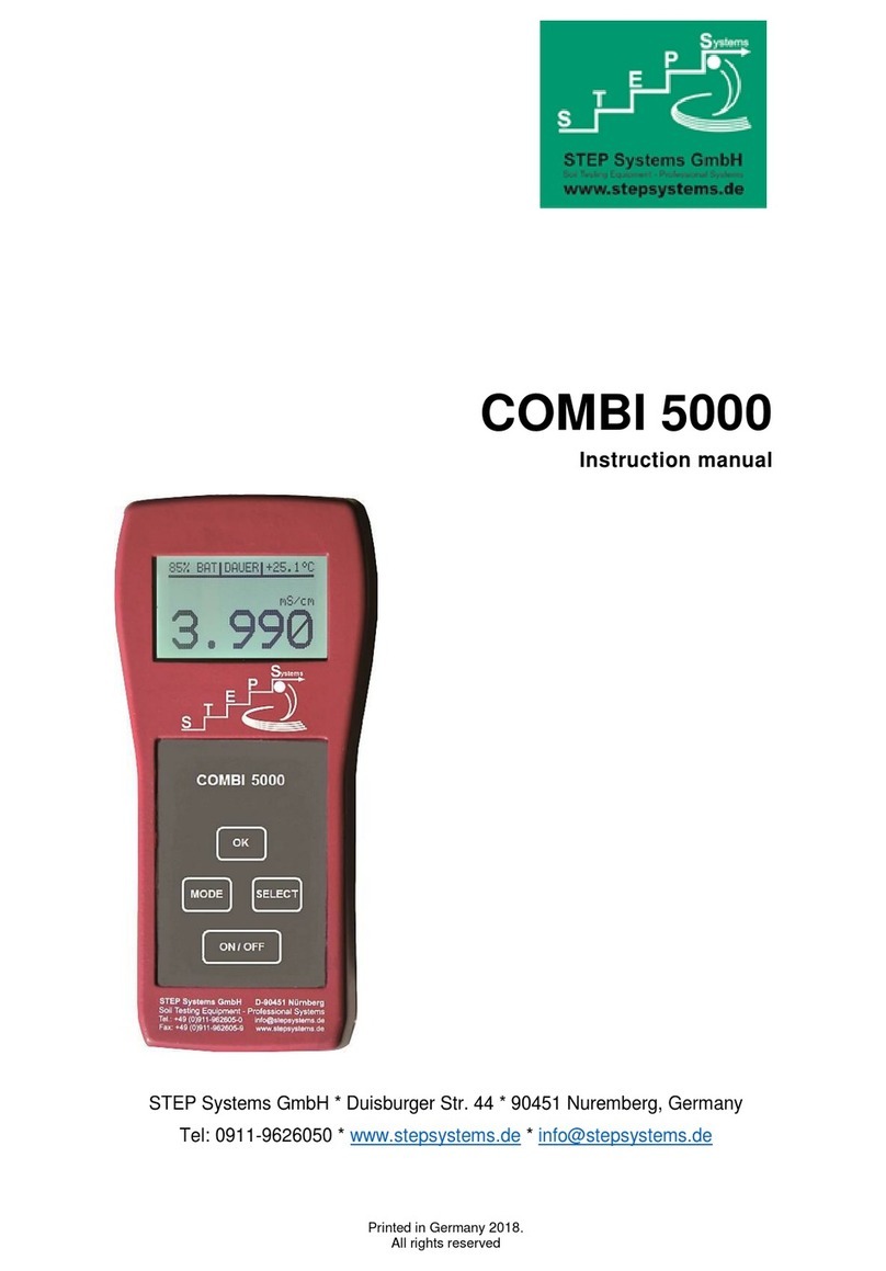
STEP OD-02 Manual

Survey meter
OD-02
OD-02 Hx
STEP Sensortechnik und Elektronik Pockau GmbH
Siedlun strasse 5-7
D-09509 Pockau


!
Table of contents
1.
OD-02 Product characteristics / scope of services ....................... 4
2.
Safety instructions .......................................................................... 5
3.
Components .................................................................................... 6
3.1.
Control elements .............................................................................................................. 7
3.1.1.
Meter switch (15) .................................................................................................... 8
3.1.2.
Zero adjuster (16) .................................................................................................... 8
3.1.3.
“ ight / Reset Dose / Reset Max Dose rate” button (12) ........................................ 8
3.1.4.
T-button “History-Table / switch dose, max dose rate” (13) .................................. 8
3.1.5.
External power supply (option) ............................................................................. 10
3.1.6.
USB interface ........................................................................................................ 10
4.
Measurin principle ....................................................................... 11
4.1.
Electrical zero adjustment ............................................................................................. 12
4.2.
Calculated air pressure correction ................................................................................. 14
5.
Measurement preparation and performance ............................... 15
5.1.
Preselection of the measuring variables ........................................................................ 15
5.2.
Dose rate equivalent measurement ................................................................................ 17
5.3.
Dose measurement ......................................................................................................... 18
5.4.
Display of the excess of the measurement range ........................................................... 18
5.5.
Special remarks for measurement performance ............................................................ 19
5.6.
Note on battery lifetime ................................................................................................. 20
5.7.
Use of the device carrier ................................................................................................ 20
6.
Stora e, handlin and transport instructions ............................. 23
7.
Cleanin of the device .................................................................. 23
8.
Service ........................................................................................... 23
Technical data ........................................................................................ 24
Appendix ................................................................................................. 26
Operation sheet OD-02 ........................................................................... 29
CE declaration of conformity ................................................................. 30

"
1. OD-02 Product characteristics / scope of services
# $ );07,0(;);07,0( Ω
′
Ω
′HH
&
%#
$ )10(*;)10(* HH
&
& '() %
*+
Optional OD-02 Hx:
$
#&'()
$%*+
Product characteristics:
,)%)
+%
- %
-
- ++#)++.#
- ++.
/- !)
0
-/%
1&-/$
/% 23
/(4%
5/3'65/3*
-/% 23/3
7%%
8%29,
:4)%%
Scope of delivery:
Optional OD-02 Hx display and control unit
%4%4
OD-02 Hx probe with detachable wall reinforcement cap
+%%
"&%9
8$
)%
Optional equipment:

5
;:%47,
74', 3*44
3%%&%$
08
γ
65/3
<
2. Safety instructions
Sensitive parts such as the soft radiation chamber must be protected
a ainst mechanical influences. Dama es to the soft radiation chamber
can cause contact volta es of up to 400 V while switched on!
%%+=
%44>
4%>
=)
%%2>
4
% 2
%
4%>
%4
$>
=>
7)
4%4>
%$%
%4:?30!>

3. Components
%$#1&-
'1*
,%+'2*
7%4%%%'3*
'4*
<'5*
Fig. 1
*
OD-02 Standard components (scope of services
4$%-
;:%44,'6*
<4'7*
0'8*
-
8&%'9*
<%'10*
Fig. 2) OD-02 optional equipment

3.1. Control elements
119,
12@9##
/&@
%
13%
A
1
%#4)
&@
14:
Fig. 3) Control elements front and rear side
15 16
15#4
16BC
17,&4'*
18;:
194&4
'*
20'*
217%
Fig. 4) Control elements and connections device front side
17 19
20
21
18

D
3.1.1. Meter switch (15)
44)
'.#)#.*4
@CEF+%
"5+
3.1.2. Zero adjuster (16)
E C E % ' + "+*
4E%C+
3.1.3. “Li ht / Reset Dose / Reset Max Dose rate” button (12)
%2 4 % % @9@# #
/& F % 4 % % +
%24+
Caution: % %
4+
<4)%24+
=)&
'*4
+%%
% @9 # # /& F 4+ =
)E&
4+
3.1.4. T-button “History-Table / switch dose, max dose rate” (13)
= .# #) %
@F%49,+:
%) ) +)
2%'+5*+
Fig. 5) Display of the measuring value history table.

G
=%5%+=
5 ) 4+
7%4+
<)@8%F'+
*9,+
Fig. 6) Display “End of Table”.
4%2%%
%+
4%4@F@&+F%E%%
!@1%#4)&F4'%"+)
+D*+
Fig. 7) Mode “dose rate“: Display “Accumulated Dose”.
Fig. 8) Mode “dose rate“: Display “Max dose rate”.

3.1.5. External power supply (option)
%%'%*4%
&,'"++ +3*+)4&
4'G*%'@7F4
@:+F%*+=%)%
"%%%9 '00*) &
+3+= 4 ) ) 4 %
)%,'G*" +3+
3.1.6. USB interface
$ 4 ;:
+ H ) 4 4 %
%+

4. Measurin principle
0 =,; % '4
$/344≤523*
$
)07,0('H
$
)07,0(H′
&
+
H ( & ) %
$
)10(*H
%$
)10(*H
&
+ $ 1I'*
1J'+KΩ*4%444
'5*-
/ % 4 4
/
L
)07,0(H′
&
)07,0('H
/%44 /
L
)10(*H
&
)10(*H
$ '
+G*+
Fig. 9) Display of the dose equivalents
: /3 '#MG* % 4
)%
)10(*H
#
)10(*H
&
+
Optional OD-02 Hx:
= ) 4 =,; )
$#-
$ 4
-
8 <
(? N23 O
(? 23N5
/3 M
(? 65/3 M
4
-
#GP%
: Q 23 O $

1&4-
%#1&&+
"+ 0#.⋅
+ % %
%%%+H)
4%%242
+ D %
+
'R5*
+
) 4
@F+
= @F)
% %
)42%
@F+
=4
%%)4+0)
4C
+ $44
+
4.1. Electrical zero adjustment
0 E C %
%
)+
<4%4'5*)
$EC'+*+

!
Fig. 10) Zero adjustment request
H)4@B8F+
EC'+G*+
Fig. 11) Zero adjustment
04)EC+=C
5S5)4-
Fig. 12) Zero adjustment O.K.
=)&4%+
+ = C % )
4-
Fig. 13) Zero adjustment beyond the specified range

"
=)%%C%
EC' *
0CE)EC' *
%+
/
$EC+
<%C
EC+
4.2. Calculated air pressure correction
%)+
H 4 ) / %
'P,)+!27*+
%
+ H ) 24
+
& %
4-
293
/273
/
760
293
/273
/
3,101 C
Torrp
C
kPap
f
°
+
⋅=
°
+
⋅=
ϑ
ϑ
p 027#
ϑ
P,+
/
-
fMM ⋅=
0
M =
f ,

5
5. Measurement preparation and performance
7%4-
+ =%%'"*
+H%)
4+,%2%
4%%
+
+ % 4+
)4'5*%HH+
& % 4
%+
5.1. Preselection of the measurin variables
% %
)10(*H
% $
)10(*H
&
44'*
-
04)%22
4 42 %
'+"*+
Fig. 14) Interlock of the wall reinforcement cap

= 4 '5* )
$
)07,0('H
)07,0(H′
&
$+:-
Optional OD-02 Hx:
In countries which have not introduced metrics regarding ICRU- Directive, the
measurement unit is the photon dose equivalent / - dose rate:
$ 4
-
8 <
(? N23 O
(? 23N5
/3 M
(? 65/3 M
4
-
#GP%
: Q 23 O $
1&4-
Caution!
44%
>
0)%
%%4+
Note:
/ ) ++ & % ) +
%%+

5.2. Dose rate equivalent measurement
7$)4'5*
% C4 @B8F EC %
4 4 + = )
%%C%EC
' *'"++*+
H$)4'5*%C
@.#F@#FEC%+=
)4'+5*+
Fig. 15) Display in run-in mode for the measuring mode µSv/h.
@F2+4%+0
) $
%'+ *+
Fig. 16) Display in the measurement mode µSv/h.
= $ ) &
4 +
&+ &)
%%%@9#
#/&F4+=)&
)E+
H & 4
)@F%
>
@ F %
@F+

D
5.3. Dose measurement
= $ )
4+
%%%@9#F
4+=)E+
For an exact dose determination as well as for measurements in pulsed radiation
fields, the measurin ran e “Dose” should be selected.
H)4%-
H)4'5*%C4
AB8@ E C % 4
4 + = ) %
C%EC' *'"+*+
H ) 4 '5* % 4
@.FCE%+
44+4
-
Fig. 17) Display in the dose measuring mode µSv.
H)@BF%
%45+EC%
+%$)%4%2@F%
45+4
E+
5.4. Display of the excess of the measurement ran e
0&'*@.#@)@.@
@#@)&%
> 1999 '+D*+=
@F) > 1999 µSv ' + D %* 2
4%45+!+

G
Fig. 18 a) Display overflow of measurement range in mode “Dose rate”.
Fig. 18 b) Display overflow of measurement range in mode „Dose“.
5.5. Special remarks for measurement performance
%+5/3', *
'*+'%*
2%+
:4&/3'G#MG*
% 4 + )
%
)10(*H
+=%4
)T%
)10(*H
&
+
=$)
%%%%
&
0 4 $)
@F%%+
=%'++4
*%+
Optional für OD-02 Hx-
%1&+5/3', *
'*+'%*
2%+
:4&/3'G#MG*
% 4 + M :
$6 23'"+5+*

=$)
%%%%
&
0 4 $)
@F%%+
=%'++4
*%+
5.6. Note on battery lifetime
O!
4%2+%
4+
%%9,'+G*
%%+=)
%+
Fig. 19) Display: battery voltage is too low
<%)%%
4+0%)
%4+
04%%
%%2+
This manual suits for next models
1
Table of contents
Other STEP Measuring Instrument manuals
