STEPCRAFT HF350 Assembly instructions

1
IMPORTANT: Read before using
Operating/Safety
Instructions
Original Operating/Safety
Instructions
Date of: 22-08-2017
Spindle HF350 / HF500
Call for consumer information
Customers from outside the U.S.
STEPCRAFT GmbH & Co. KG
An der Beile 2
58708 Menden
Germany
Phone: 0049-2373-179 11 60
E-mail: info@stepcraft-systems.com
Customers from the U.S. / Canada
STEPCRAFT Inc.
59 Field Street, Rear Building
Torrington, CT, 06790
United States
Phone: 001-203-5561856
E-mail: info@stepcraft.us

NOTICE
All instructions, warranties and other collateral documents are subject to change at the sole discretion of
STEPCRAFT, Inc. For up-to date product literature, visit www.stepcraft-systems.com for customers from Europe
or www.stepcraft.us, for customers from US / Canada and click on the service & support tab for this product.
Meaning of Special Language
The following terms are used throughout the product literature to indicate various levels of potential harm when
operating this product: The purpose of safety symbols is to attract your attention to possible dangers. The safety
symbols, and their explanations, deserve your careful attention and understanding. The safety warnings
themselves do not eliminate any danger. The instructions or warnings they give are not substitutes for proper
accident prevention measures.
NOTICE
Procedures, which if not properly followed, create a possibility of physical property damage
AND little or no possibility of injury.
CAUTION
Procedures, which if not properly followed, create a probability of physical property damage
AND a possibility of serious injury.
WARNING
Procedures, which if not properly followed, create a probability of property damage, collateral
damage, serious injury or death OR create a high probability of superficial injury.
Safety Alert: Indicates caution or warning. Attention is required in order to avoid serious
personal injury.
Read the ENTIRE instruction manual in order to become familiar with the features of the
product and how to operate them. Failure to operate the product correctly can result in damage
to the product, personal property and cause serious injury, electric shock and/or fire.
This is a sophisticated hobby and a semi-professional product for advanced craftsmen with previous experience
in the operation of tools such as electric drills, routers and computerized tools like CNC routers or 3D printers. It
must be operated with caution and common sense and requires some basic mechanical ability. Failure to operate
this product in a safe and responsible manner could result in personal injury or damage to the product or other
property. This product is not intended for use by children without direct adult supervision. Do not attempt
disassembly, use with incompatible components or augment product in any way without the approval of
STEPCRAFT GmbH & Co. KG or STEPCRAFT, Inc. This manual contains instructions for safety, operation and
maintenance. It is essential to read and follow all the instructions and warnings in the manual, prior to assembly,
setup or use, in order to operate correctly and avoid damage or serious injury.
Age Recommendation: For advanced handcrafters ages 14 and above. This is not a toy.
SAVE ALL WARNINGS AND INSTRUCTIONS FOR FUTURE REFERENCE.
Should you encounter any doubts or require any further information, please do not hesitate to contact us
before commissioning of the power tool. Our contact details can be found on the front page of this
manual.
The term “power tool” in the warnings refers to your mains-operated (corded) power supply and the spindle itself,
hereafter referred to as STEPCRAFT high frequency spindle or “HFS”.
General Power Tool Safety Warnings
Work area safety
Keep work area clean and well lit. Cluttered or dark areas invite accidents.
Do not operate power tools in explosive atmospheres, such as in the presence of flammable
liquids, gases or dust. Power tools create sparks which may ignite the dust or fumes.
NOTICE
Keep children and bystanders away while operating a power tool. Distractions can cause you to
lose control and can result in accidents.
Continued on next page

3
Electrical safety
Power tool plugs must match the outlet. Never modify the plug in any way. Do not use any
adapter plugs with earthed (grounded) power tools. Unmodified plugs and matching outlets will
reduce the risk of electric shock.
Avoid body contact with earthed or grounded surfaces such as pipes, radiators, ranges and
refrigerators. There is an increased risk of electric shock if your body is earthed or grounded.
Do not expose power tools to rain or wet conditions. The spindle is only suitable for indoor
use. Water entering a power tool will increase the risk of electric shock.
Do not abuse the cord. Never use the cord for carrying, pulling or unplugging the power
tool. Keep cord away from heat, oil, sharp edges or moving parts. Damaged or entangled
cords increase the risk of electric shock.
If operating a power tool in a damp location is unavoidable, use a Ground Fault Circuit
Interrupter (GFCI). The use of a GFCI reduces the risk of electric shock.
Personal safety
Stay alert, watch what you are doing and use common sense when operating a power tool.
Do not use a power tool while you are tired and/or under the influence of drugs, alcohol or
medication. A moment of inattention while operating power tools may result in serious personal
injury.
NOTICE
All persons who operate the power tool must have read and fully understood all relevant
operating instructions. Misunderstanding may result in personal injury.
Use personal protective equipment. Always wear eye protection. Protective equipment such
as a dust mask or hearing protection used for appropriate conditions will reduce personal injuries.
Prevent unintentional starting. Ensure the switch is in the off-position before connecting
the power tool to the power source, picking it up or carrying the tool. Carrying power tools
with your finger on the switch or energizing power tools that have the switch on invites accidents.
NOTICE
Remove any adjusting key or wrench before turning the power tool on. A wrench or a key left
attached to a rotating part of the power tool may result in personal injury.
Do not overreach. Keep proper footing and balance at all times. This enables better control of
the power tool in unexpected situations.
NOTICE
Dress properly. Do not wear loose clothing or jewelry. Keep your hair, clothing and gloves
away from moving parts. Loose clothes, jewelry or long hair can be caught in moving parts.
If devices are provided for the connection of dust extraction and collection facilities, ensure
these are connected and properly used. Use of dust collection can reduce dust-related hazards.
Power tool use and care
Do not force the power tool. Use the correct power tool for your application. The correct
power tool will do the job better and safer at the dedicated rate for which it was designed.
NOTICE
Do not use the power tool if the switch cannot be turned on and/or off. Any power tool that
cannot be controlled with the switch is dangerous and must be repaired.
Disconnect the plug from the power source and/or the battery pack from the power tool
before making any adjustments, changing accessories, or storing power tools. Such
preventive safety measures reduce the risk of starting the power tool accidentally.
Store idle power tools out of the reach of children and do not allow persons unfamiliar with
the power tool or these instructions to operate the power tool. Power tools are dangerous in
the hands of untrained users.
NOTICE
Maintain power tools. Check for misalignment or binding of moving parts, breakage of parts
and any other conditions that may affect the power tool's operation. If damaged, have the
power tool repaired before use. Many accidents are caused by poorly maintained power tools.
Keep cutting tools sharp and clean. Properly maintained cutting tools with sharp cutting edges
are less likely to bind and are easier to control by the machine.
Use the power tool, accessories and end mills etc. in accordance with these instructions,
taking into account the working conditions and the work to be performed. Use of the power
tool for operations different from those intended could result in a hazardous situation.
Continued on next page

4
Service
Have your power tool serviced by a qualified repair person using only identical replacement
parts. This will ensure that the safety of the power tool is maintained.
Safety Rules for Rotary Tools
Make sure that the power tool cannot cut its own cord, therefore never install the power
cord across the machine table. Cutting a "live" wire may shock the operator.
Use clamps or another practical and secure way to support the workpiece and secure it to
the machine table. Holding the workpiece with your hands leaves it unstable and may lead to loss
of control.
NOTICE
Accessories must be rated for at least the speed recommended on the tool warning label.
Accessories running over rated speed can fly apart and cause injury.
Always disconnect the power cord from the power source before making any adjustments
or attaching any accessories. You may unexpectedly cause the tool to start leading to serious
personal injury.
Be aware of the switch location, when placing the tool down or when picking the tool up.
You may accidentally activate the switch.
Do not hold the spindle in your hands during the start-up. The reaction torque of the motor, as
it accelerates to full speed, can cause the shaft to twist.
NOTICE
Always wear safety goggles and dust mask. Use only in well ventilated area. Using personal
safety devices and working in safe environment reduces risk of injury.
After changing the bits or making any adjustments, make sure the ER collet and the
clamping nut are both securely tightened. Loose adjustment devices can unexpectedly shift,
causing loss of control. Loose rotating components will be violently thrown.
This is not a handheld tool. The spindle is designed to be system-guided and must be
operated in a CNC router or a Desktop CNC System. Operation of the power tool handheld may
result in serious personal injury.
NOTICE
Do not reach in the area of the spinning bit. The proximity of the spinning bit to your hand may
not always be obvious.
NOTICE
Do not operate wire and bristle brushes with the spindle. Bristles or wires will be discharged
from the brush at high speeds, can fly apart and cause injury.
Never use dull or damaged bits. Sharp bits must be handled with care. Damaged bits can
snap during use. Dull bits require more force to push the tool, possibly causing the bit to break.
Use clamps to support the workpiece. Never hold a workpiece with your hands.
Inspect your workpiece before cutting. For example, if carving wood, make sure there are
no nails or foreign objects in the workpiece. Nails or foreign objects can cause the bit to break.
The speed and feed of the bit when carving, routing or cutting is very important. Always
observe the speed and feed for the particular bit recommended.
If the workpiece or bit becomes jammed or bogged down, turn the power tool "OFF" by the
switch. Wait for all moving parts to stop and unplug the tool, then work to free the jammed
material. If the switch to the tool is left "ON" the tool could restart unexpectedly causing serious
personal injury.
NOTICE
Do not leave a running tool unattended, turn power off. Only when tool comes to a complete
stop and is disconnected from the mains is it safe.
Do not touch the bit or collet after use. After usage bit and collet are too hot to be touched with
bare hands.
Clean the tool's air vents every 4 hours by using compressed air. Excessive accumulation of
powdered metal inside the motor housing may cause electrical failures.
NOTICE
Do not allow familiarity gained from frequent use of your rotary tool to become
commonplace. Always remember that a careless fraction of a second is sufficient to inflict severe
injury.
Do not alter or misuse tool. Any alteration or modification is a misuse and may result in serious
personal injury.
This product is not intended for use as a dental drill, in human or veterinary medical
applications. Serious personal injury may result.
When using the end mills, V-bits or cutters, always have the workpiece securely clamped.
Never attempt to hold the workpiece with your hands while using any of these accessories.
The reason is that these tools will grab if they become slightly canted in the groove, and can
kickback causing loss of control resulting in serious injury.
Continued on next page

5
Safety Rules for System-guided Tools
The spindle can be controlled by a control software of a CNC router. Therefore the power
supply of the spindle has to be properly connected to the external output of the main board
of the CNC router via a 15-pin Sub-D cable. Prior to each commissioning of the power tool the
ON/OFF, speed and emergency button functionality has to be checked. Malfunction may result in
serious personal injury.
NOTICE
Do not leave a running CNC System and power tool unattended, turn power off. Only when a
CNC router or power tool come to a complete stop and are disconnected from the mains are they
safe.
Additional Safety Warnings
Depending on the application field of the machine (private or commercial), observe the applicable
occupational safety and health, safety and accident prevention and environmental regulations, too.
NOTICE
GFCI and personal protection devices like electrician's rubber gloves and footwear will
further enhance your personal safety.
Do not use AC only rated tools with a DC power supply. While the tool may appear to work,
the electrical components of the AC rated tool are likely to fail and create a hazard to the operator.
Use clamps or another practical way to secure and support the workpiece to the machine
table. Holding the workpiece with your hands leaves it unstable and may lead to loss of control.
Develop a periodic maintenance schedule for your tool. When cleaning a tool be careful not to
disassemble any portion of the tool since internal wires may be misplaced or pinched or safety
guard return springs may be improperly mounted. Certain cleaning agents such as gasoline,
carbon tetrachloride, ammonia, etc. may damage the surface.
Risk of injury to user. The power cord must only be served by a STEPCRAFT service facility.
Some dust created by power cutting, routing, milling, drilling, and other construction
activities contains chemicals known to cause cancer, birth defects or other reproductive
harm. Some examples of these chemicals are: Lead from nonferrous metals with lead
content, carbonate from carbon fiber, arsenic and chromium from chemically-treated
lumber.
Your risk from exposures to these varies, depending on how often you do this type of work. To
reduce your exposure to these chemicals: work in a well ventilated area, and work with approved
safety equipment, such as those dust masks that are specially designed to filter out microscopic
particles.

6
Symbols
IMPORTANT: Some of the following symbols may be used on your tool. Please study them and learn their
meaning. Proper interpretation of these symbols will allow you to operate the tool better and safer.
Symbol
Name
Designation / Explanation
V
Volts
Voltage (potential)
A
Amperes
Current
Hz
Hertz
Frequency (cycles per second)
W
Watt
Power
Kg
Kilograms
Weight
Min
Minutes
Time
S
Seconds
Time
mm
Length, Height, Width
Size in millimeter (metric)
inch
Length, Height, Width
Size in inch
Ø
Diameter
Size of drill bits, end mills, etc.
…/min
Revolutions or reciprocation per
minute
Revolutions, turns, etc. per minute
V
→
, V
↓
Speed
Horizontal / vertical speed in millimeter per second
0
Display off position
Zero speed / revolution per minute
15, 45, 75, 99
Display selector settings
Speed / revolution per minute as percentage share
of the max. speed / revolution. Higher number
means greater speed. 99 equal the max. revolution
per minute.
→
Arrow
Action in the direction of an arrow
Warning symbol
Alerts user to warning messages
CAUTION hot surface
Alerts user not to touch the surface – danger of
burns
CAUTION rotating tool
Alerts user not to touch the blade / the insertion
tool - danger of lacerations
Wear eye protection symbol
Alerts user to wear protective glasses
Wear hand protection symbol
Alerts user to wear protective gloves
Grounding symbol
Alerts user to ground the power tool / electrical
system
Wear ear protection symbol
Alerts user to wear a hearing protector
Read manual symbol
Alerts user to read manual BEFORE first
commissioning
Unplug symbol
Alerts user to unplug the device BEFORE servicing
the power tool
Disposal symbol
Instructions for disposal of WEEE by users of the
European Union

7
Content
1GENERAL INSTRUCTIONS................................................................................ 9
1.1 Information and Explanations to the Operating Instructions......................................9
1.2 Description of Components ......................................................................................9
1.3 Intended Use............................................................................................................9
2Design and Function.........................................................................................10
2.1 Designation of the Individual Parts of the Spindle...................................................10
2.2 Designation of the Controller Components .............................................................10
3Start-up ..............................................................................................................11
3.1 Clamping the Spindle .............................................................................................11
3.2 Environmental Requirements .................................................................................11
3.3 Electrical Connection of the Control unit.................................................................11
3.4 Emergency Stop.....................................................................................................12
3.5 Optional Accessories..............................................................................................12
3.5.1 Collets.............................................................................................................12
3.5.2 Insertion Tools.................................................................................................12
4Operator Control / Spindle ...............................................................................13
4.1 Operator.................................................................................................................13
4.2 Control Unit ............................................................................................................13
4.3 Spindle ...................................................................................................................14
4.4 Replacing the Collets .............................................................................................15
4.5 Emergency-stop Switch..........................................................................................15
4.5.1 Operation ........................................................................................................15
4.5.2 Testing the Spindle on / off and Emergency-stop Functionality .......................16
4.6 Speed and Feed Settings.......................................................................................16
5Technical Specifications ..................................................................................18
5.1 Dimensions and Weight of the Spindle...................................................................18
5.2 Other Characteristics of the Spindle .......................................................................18
5.3 Pin Assignment of the Interface (15-pin D-sub Input Signals).................................18
5.4 Spare Parts ............................................................................................................18
6Transport / Storage...........................................................................................18
6.1 Transport................................................................................................................18
6.2 Packaging ..............................................................................................................18
6.3 Storage ..................................................................................................................19

8
7Maintenance Information..................................................................................19
7.1 Service...................................................................................................................19
7.2 Cleaning.................................................................................................................19
7.3 Extension Cords.....................................................................................................19
8Failure ................................................................................................................20
8.1 Response to Malfunctions ......................................................................................20
9Annex .................................................................................................................20
9.1 Warranty and Service Contact information .............................................................20
9.2 Manufacturer..........................................................................................................21
9.3 Type Plate..............................................................................................................21
9.4 Copyright................................................................................................................21
9.5 Limited Warranty ....................................................................................................21
9.6 Instructions for Disposal of WEEE by Users of the European Union.......................23
9.7 RoHS, 2002/95/EG ................................................................................................23
9.8 EC-Declaration of Conformity.................................................................................24

9
1 GENERAL INSTRUCTIONS
1.1 INFORMATION AND EXPLANATIONS TO THE OPERATING INSTRUCTIONS
This manual is intended to familiarize you with your STEPCRAFT High Frequency Spindle (hereafter referred to
as HFS) and its control system, providing you with all the necessary information you will need in order to operate
it safely and professionally.
Please read this manual thoroughly and carefully prior to the first use of your STEPCRAFT
HFS. Operate the machine and the associated control system only when you are sure that you
have understood these instructions in their entirety. Hereby you minimize the risk of injury and / or
prevent property damage.
Should you encounter any doubts or require any further information, do not hesitate to contact us. Our contact
information can be found on the front page of this manual.
Keep this manual always in close proximity to the STEPCRAFT HFS for future reference.
We cannot be held accountable either for any kind of injury and / or property damage resulting from improper
handling deviating from the recommended use of the STEPCRAFT HFS or from failure to follow the safety
regulations properly (see page 2 cont.).
We reserve the right to further develop the spindle as well as the control system.
1.2 DESCRIPTION OF COMPONENTS
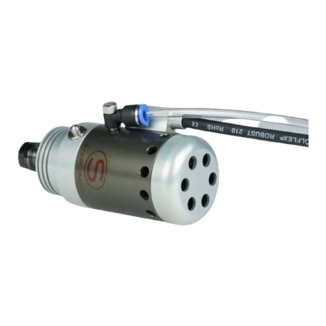
The STEPCRAFT HFS consists of the milling spindle with the firmly attached cabling and a matching controller /
frequency inverter. The spindle has a 43-mm collar as well as an active air cooling system. The milling cutters are
mounted using ER11 collets. The lateral shaft lock button allows for a convenient tool change.
The ready-to-use unit consists of the following components:
1. Pre-built frequency converter in sheet steel housing
2. HF Spindle with a permanently attached cable and plug
3. Connection cable 15-pin Sub-D male-female
4. Operating instructions
For more information on optional accessories, see item 3.5 of this manual.
1.3 INTENDED USE
The STEPCRAFT HFS has been developed for private users (e. g. model designers) and for single or small batch
production in the commercial sector. It is not suitable either for large-scale production or for integration into
assembly lines. It is designed for the usage of cutters and engraving burins with a diameter up to 8 mm. The HFS
is specifically designed for installation and connection to our STEPCRAFT machine series - Plug & Play.

10
2 DESIGN AND FUNCTION
Disconnect the plug from the power source before making any assembly, adjustment or
change of accessories. Such preventive safety measures reduce the risk of starting the tool
accidentally.
2.1 DESIGNATION OF THE INDIVIDUAL PARTS OF THE SPINDLE
1 = Cable lead
2 = Exhaust cover with air outlet openings
3 = Air intake openings
4 = Shaft lock button
5 = 43 mm Euro-neck intake
6 = ER11 collet nut
2.2 DESIGNATION OF THE CONTROLLER COMPONENTS
1 = Engine on / off LED
2 = Engine on / off switch
3 = Rotational speed "manual" setting
4 = Rotational speed display in %
5 = Main switch
6 = Signal input (STEPCRAFT system bus)
7 = Spindle screw jack
8 = Power supply
1
2
3
4
5
6

11
3 START-UP
Always unplug rotary tool before changing accessories, collets or servicing your rotary
tool.
3.1 CLAMPING THE SPINDLE
The spindle is inserted, without any additional adapter, directly into the 43 mm Euro-tensioning system of the
machine and is easily fixed. The shaft lock button (4) of the spindle should be facing forward. Thus, a simple tool
change is possible.
The connecting cable and the hose of the spindle must run clean on the side, so that they cannot get caught in
between the sideways of the machine.
3.2 ENVIRONMENTAL REQUIREMENTS
Attach the spindle to the 43 mm Euro-tensioning system of the STEPCRAFT machine or the adequate CNC
router. Set the controller up in such a way that the cable feed cannot be crushed.
Make sure that there is sufficient room around the system so that you can work comfortably and the machine can
fully extend its traversing paths. Maintain a sufficient safety distance from other machines.
The air surrounding the spindle is to be kept low-dust. An excessive exposure to dust may cause damage to the
spindle.
Humidity should be within the usual levels for indoor environments. Protect the spindle against moisture and
humidity. The ideal temperature of the system is between 18°C and 25°C.
Especially protect the electronics from overheating by avoiding exposure of the spindle and the controller to direct
sunlight or close proximity to a heater.
Provide adequate lighting for the location of the machine and the work places surrounding it.
Position the PC controlling the machine in its near proximity in order to have both of them in clear view. All the
instructions relevant to the machine and its components must be always kept nearby and within reach.
3.3 ELECTRICAL CONNECTION OF THE CONTROL UNIT
Connect the control unit to the system output of your STEPCRAFT Desktop CNC System using the supplied 15-
pin Sub-D connection cable.
NOTICE: If you have a CNC router from a different brand check the external documentation to connect the
spindle to the data output of the specific CNC router (see also item 5.3)
The control unit must be connected to the 110 V or 230 V mains respectively.
NOTICE: If the control unit is prepared with a NEMA 15-5 plug, 110 V are required (US model, see picture
below). All other models have EU-specifications and require 220-240 V.

12
3.4 EMERGENCY STOP
The emergency-stop switch is located on the front of the machine (see figure in item 3.1 STEPCRAFT 3D
Desktop Operating Instructions).
Pressing the switch triggers an emergency stop of the machine´s operation. Simultaneously, the power supply to
the control system is interrupted. In addition, the control software receives a signal to stop the operation. The
machine will stop immediately.
The emergency stop switch can only lead to a cessation of all components when they are
properly connected to the emergency stop functionality of the mainboard.
If you are using third-party products, such as another control device, you are solely
responsible for connecting the emergency stop functionality properly to the HFS controller.
Otherwise a danger of personal injury or damage to property arises!
Even if you wish to use a system-held tool, such as a drilling and milling spindle, which has
a separate on-off switch and is NOT controlled by the PC, you must ensure that these are
connected correctly to the emergency-stop functionality of the mainboard. If you fail to do
so, the tool will continue to run even when the emergency stop switch is being pressed.
This poses a great danger to persons and property!
If you have any further questions, please do not hesitate to contact us!
For further information on the emergency-stop switch, refer to item 4.5 of this manual.
3.5 OPTIONAL ACCESSORIES
If you wish to use accessories not manufactured or sold by STEPCRAFT, make sure to check their compatibility
with your system prior to its first application.
When in doubt, contact the manufacturer.
3.5.1 COLLETS
The spindle is not supplied with an ER11 collet. The following collets are available as options:
ER11 collet ø 1.0 mm
ER11 collet ø 5.0 mm
ER11 collet ø 2.0 mm
ER11 collet ø 6.0 mm
ER11 collet ø 2.5 mm
ER11 collet ø 7.0 mm
ER11 collet ø 3.0 mm
ER11 collet ø 8.0 mm
ER11 collet ø 3.175 mm (1/8’’)
ER11 collet nut M14x0.75 mm
ER11 collet ø 4.0 mm
All collets are available separately in our online shop.
3.5.2 INSERTION TOOLS
Please note that the spindle and the machine can get overloaded quickly with the use of tools with large milling
cutters. Therefore, use a customized step-over and an adaptable feed. Take into consideration that larger tools
which are not finely balanced can lead to strong vibrations.
Different tools with various diameters (mostly between < 1.0 mm to 8.0 mm) are available. The shank sizes vary
between 3.175 mm (1/8´´) and 4, 6 or 8 mm.

13
Type of tool
Technical specification
Applications
End mill 2-flute fish
- Solid carbide-end mill Ø1.0 mm
- Double-flute
- Fishtail bottom
- Upcut- or downcut spiral
- Universally applicable
- Aluminum
- Plastics
- Wood
End mill diamond
- Solid carbide-end mill Ø1.0 mm
- Diamond toothed
- Fishtail
- Glass fiber
- Carbon fiber
- Wood
- Printed circuit boards
End mill single flute
- Solid carbide-end
- Single-flute
- Flat bottom
- Upcut- or downcut spiral
- High quality contours
- Has only one flute, much space for chip
evacuation
- Very good for soft materials
- Soft plastics
- PE, teflon, plexiglas, styrofoam
- Soft aluminum
End mill spiral
- Solid carbide-end mill Ø 2 mm
- Spiral toothed
- Fishtail
- Upcut- or downcut spiral
- Glass fiber
- Carbon fiber
- Wood
- Printed circuit boards
Radius mill
- Solid carbide-radius mill
- Center cut (diving possible)
- Universal usability of all materials
- Wood
- Aluminum
- Non-ferrous metals
V-bit
- Solid carbide V-router bit
- tip angel from 30° to 120°
- Single-cut with upcutting spiral
- Engraving printed circuit boards
- Engravings on many materials
- Chamfering
4 OPERATOR CONTROL /SPINDLE
4.1 OPERATOR
The improper operation of the spindle and the control unit can cause serious injury and / or property damage.
Read and observe the major accident prevention regulations!
Each user must have read and understood the available instructions for the entire system (machine, system-held
tool, control and software) before proceeding to operate the device for the first time.
4.2 CONTROL UNIT
After switching on the control unit, it connects to the spindle engine. Upon a successful connection, an audible
confirmation can be heard (5 tones). The spindle is now ready for operation. The set point speed can be
preselected at the speed dial (3). If you press the (2) button, the spindle begins to turn and rotates at the preset
speed. A Reliable starting of the spindle is guaranteed from 15% speed specification.
The speed may be adjusted during operation through the dial or between any of the settings.
Refer to the chart in item 4.6 to determine the proper speed and feed, based on the material being
processed and the type of accessory being used. These charts enable you to choose both correct
accessory and the optimum speed at a glance.
The speed of the HFS is manually controlled by adjusting this dial on the controller.

14
Settings for approximate revolutions
Switch setting
Speed range
20
20% of the maximum speed, approx. 4,000 RPM
40
40% of the maximum speed, approx. 8,000 RPM
60
60% of the maximum speed, approx. 12,000 RPM
80
80% of the maximum speed, approx. 16,000 RPM
99
99% of the maximum speed, approx. 20,000 RPM
The spindle can also be "remote controlled" with the 15-pin D-sub cable by means of the machine software and
the program loaded. You can start and stop the HFS either via command line or the signal test of the control
software. Please refer to the manual of the control software.
G-code command to start / stop the spindle
Command
Function
M03 S5000
Starts the spindle (clockwise) with a revolution of 5,000 RPM. The maximum value
for the revolution can be S20000.
M05
Stops the spindle
4.3 SPINDLE
Never touch the tool! This poses a serious risk of injury!
To change a tool, block the spindle by pressing the shaft lock button (4). Using a 17 mm open-end wrench, the
lock nut can now be released and screwed down (see picture below).
Do not engage shaft lock while the rotary tool is running!

15
4.4 REPLACING THE COLLETS
The collets must snap into the clamping nut. Only then, a correct clamping of the end mill and, above all, a re-
release of the collet are possible.
Change of ER collets
1.
Move tongue of clamping
nut diagonal into the ER
collet until a click is being
heard (pic. 1).
2.
If the ER collet is in the
correct position (pic. 2),
cutters, end-mills, etc.
can be inserted.
3.
Pic. 3 shows the wrong
insertion of the ER collet.
4.5 EMERGENCY-STOP SWITCH
4.5.1 OPERATION
The emergency-stop switch is located on the front of the STEPCRAFT Desktop CNC System. Pressing the
emergency button leads to an emergency stop of the machine and the HFS. The machine will stop immediately.
Actuate the emergency-stop switch only in emergency situations.
NOTICE: Actuating the emergency-stop will result in immediate machine shutdown and can cause step and
data losses.
Controlled cessation of the machine´s operation can only be effectuated via the control software.
To cancel the emergency stop status, turn the emergency-stop switch to the right. Then the control is re-enabled.
The work process must be restarted.
The entire system is controlled and operated by the PC.
Prior to first usage, read the manual of your control software thoroughly and carefully,
making sure that you have understood everything.
For questions regarding the control software, please contact the respective software developer.

16
4.5.2 TESTING THE SPINDLE ON /OFF AND EMERGENCY-STOP FUNCTIONALITY
For testing the on / off and emergency-stop functionality with the control software of the machine, the spindle
must be connected to the HFS controller. Additionally, the HFS controller has to be connected to the mainboard of
the machine by using the Pin-15 D-sub cable.
NOTICE: For questions regarding the control software, please contact the respective software developer.
Manual test:
- Start the control software of the CNC router / STEPCRAFT Desktop 3D System.
- Mount the spindle on the tensioning system of the machine.
- Switch on the HFS controller, an audible confirmation can be heard. Do not start the spindle.
- Start the spindle with the signal test / I/O (if applicable) of the control software of the machine.
- Press the emergency button, the spindle should stop immediately.
Automatic operation:
For an automatic operation you need to prepare a file for the control software of the machine:
G21; set units to millimeters
G91 ; use relative coordinates
M3 S5000 ; spindle start
G1 F500.000 Y-40.00000 ; feed with 500 mm/min.
G1 F500.000 X-40.00000 ; feed with 500 mm/min.
G1 F500.000 Y40.00000 ; feed with 500 mm/min.
G1 F500.000 X40.00000 ; feed with 500 mm/min.
M5 ; spindle stop
M30 ; program end
Prepare the file with an ASCII-editor of your computer, for example notepad.exe, and save it as “test.nc” file.
- Start the control software of the CNC router / STEPCRAFT Desktop 3D System.
- Mount the spindle on the tensioning system of the machine.
- Switch on the HFS controller, an audible confirmation can be heard. Do not start the spindle.
- Start the homing sequence of the CNC router / STEPCRAFT Desktop 3D System.
- Load the “test.nc” file.
- Jog the gantry to the middle position of each axis (X, Y, Z) and save this position as zero position of the
imaginary workpiece.
- Start the program, the spindle should start and the machine drives a square of 40 mm by 40 mm. After
completing the square, the spindle stops and the program ends.
- Start the program again and press the emergency button during the program sequence, machine and
spindle should stop immediately.
4.6 SPEED AND FEED SETTINGS
Many applications and accessories (insertion tools, for example an end mill cutter) will provide the best
performance at full speed, but for certain materials, applications and accessories you need to proceed with slower
speeds, which is the reason a variable speed control is available.
Certain materials (some plastics and precious material, for example) however, require a relatively slow speed and
feed because, at high speed, the friction of the insertion tool generates heat and may cause damage to the
material and the accessory.
Hardwoods and metals require high speed operation.
To aid you in determining the optimum operational speed and feed for different materials and accessories, we
compiled a table. By referring to this table, you can discover the recommended speeds and feeds for each type of
accessory / workpiece material. Examine this table properly and become familiar with it.

17
Ultimately, the best way to determine the correct speed and feed for work on any material, is to practice on a
piece of scrap, even after referring to the chart. You can quickly learn that a slower or faster speed / feed is more
effective, just by observing what happens during processing a pass or two at different speeds / feeds. When
working with plastic, for example, start at a slow rate of speed / feed and increase the speed until you observe
that the plastic is melting at the point of contact. Then reduce the speed slightly to get the optimum working
speed. Secondly increase the feed until you observe that the accessory starts to chatter at the point of contact.
Then reduce the feed or the infeed depth slightly to get the optimum working feed and infeed depth.
Some rules of thumb in regard to speed / feed / infeed depth:
1. Plastics and other materials that melt at low temperature should be cut at low speeds.
2. Wood should be cut at high speeds.
3. Hardwoods, carbon fiber and aluminum should be cut at high speeds. If the end mill starts to chatter, this
normally means it is running too slow or the feed / infeed depth has to be reduced.
4. Aluminum, copper and brass may be cut at various speeds, depending on the type of cutting being done.
Use suitable cutting oils on the end mill in order to prevent the cut material from adhering to the cutter
teeth and to support the cutting process.
5. Check the material composition. Every material has its own characteristics and some materials are hard
to cut, for example aluminum if it is not an alloy suitable for cutting / milling.
If the insertion tool is not performing as you think it should, perhaps you should be using a different accessory and
probably an adjustment in speed / feed / machine setting, a play-free system is mandatory, would solve the
problem.
MID = Maximum infeed depth per cycle [mm]
RPM = Revolution per minute of the HFS [1000x n/min.]
V→ = Horizontal feed speed (X-/Y-direction) [mm/s]
V↓ = Vertical speed (Z-direction) [mm/s]
Ø = Diameter of end mill [mm]
Ø 1
Ø 2
Ø 3
Material
Type of end mill
MID
RPM
V↓
V→
MID
RPM
V↓
V→
MID
RPM
V↓
V→
Softwood
End mill spiral
5
20
4
12
6
15
5
18
8
10
5
14
Hardwood
End mill spiral
2
18
3
4
3
12
4
6
4
8
4
5
Carbon fiber
End mill
diamond or
spiral
3
20
3
4
3
16
4
4
2
12
4
3
Glass-fiber
reinforced
plastic
End mill
diamond or
spiral
3
20
3
4
3
16
4
4
2
12
4
3
Soft plastic
End mill single
flute
5
12
4
4
6
12
5
6
8
6
5
6
Hard plastic
End mill single
flute
2
18
3
3
3
14
4
5
4
10
3
4
Acrylic glass
End mill 2-flute
fish
2
15
1
3
3
12
2
5
3
8
2
4
Aluminum
(alloy with
plumb)
End mill 2-flute
fish
0.5
20
1
2
1
17
1
2
1
14
1
2
Brass
End mill 2-flute
fish
0.5
20
1
2
1
17
1
2
1
14
1
2
NOTICE: The table expresses a guideline only; the optimum working speed depends on machine size and
play-free assembly, condition of spindle and insertion tool as well as on quality of workpiece material.
NOTICE: Engraving cutters (V-bit) should run at maximum speed with twice as much feed as mentioned in the
table above. The maximum infeed depth should be 0.3 mm.

18
5 TECHNICAL SPECIFICATIONS
5.1 DIMENSIONS AND WEIGHT OF THE SPINDLE
- Length: 130 mm
- Diameter: 52 mm
- Weight: 0.65 kg
- Clamping neck: 43 mm (Euro neck)
- Cable length: approx. 2 m / 6 feet
5.2 OTHER CHARACTERISTICS OF THE SPINDLE
- Collet diameter: ER11, max. 8.0 mm
- Housing: Aluminum 7075 anodized,
- Type of the engine: Three-phase asynchronous engine
- Speed range: 3000-20000 rpm, clockwise rotation (15 – 100%)
- Electronic control: Governor electronic to provide maximum torque at all speeds
- Maximum voltage: 24 V
- Maximum current: 14.6 A / 20.8 A
- Maximum torque: 0.17 Nm / Nm 0.25
- Maximum cutting force (Ø 2mm): 163 N / 240 N
- Maximum performance: 350 W / 500 W
- Type and number of ball bearings: Steel, lubricated for life, 3x
- Run-out in the clamping taper in mm: <0.01
- Cooling: Labyrinth air cooling
- Additional features: Shaft lock button
5.3 PIN ASSIGNMENT OF THE INTERFACE (15-PIN D-SUB INPUT SIGNALS)
Pin number
Function
Pin number
Function
1
Not used
9
Not used
2
GND (mass)
10
GND (mass)
3
Not used
11
Not used
4
Not used
12
Not used
5
Not used
13
Spindle on / off
6
Not used
14
Not used
7
PWM Signal
(0-5V)
15
Not used
8
Not used
---
---
5.4 SPARE PARTS
All parts of the spindle and the controller can be purchased separately.
Our contact details can be found on the front page of this manual.
6 TRANSPORT /STORAGE
6.1 TRANSPORT
Please make sure that the spindle is not exposed to heavy shocks during transport. This can lead to unwanted
vibrations. If necessary, transport the device in suitable containers.
6.2 PACKAGING
If you do not want to re-use the packaging material of the spindle and the control unit, remove it properly and
according to disposal conditions at the site and carry it to the recycling or disposal unit.

19
6.3 STORAGE
In case of prolonged downtime of the spindle and the control unit please observe the following storage conditions:
- Store the device and its components in an indoor environment.
- Protect from moisture, humidity, cold, heat and direct sunlight.
- Store in a dust-free environment, cover if necessary.
- The storage site should be free of any vibrations.
7 MAINTENANCE INFORMATION
7.1 SERVICE
To ensure continued enjoyment of your STEPCRAFT HFS, handle it carefully.
Regular maintenance positively affects the life expectancy of the device.
Preventive maintenance performed by unauthorized personnel may result in misplacing of
internal wires and components which could cause serious hazard. We recommend that all
tool service be performed by a STEPCRAFT service facility.
To avoid injury from unexpected starting or electrical shock, always remove plug from wall
outlet before performing service or cleaning.
The HFS has ball bearing construction. Under normal use no additional lubrication is required.
7.2 CLEANING
To avoid accidents always disconnect the rotary tool from the power supply before
cleaning or performing any maintenance. The tool may be cleaned most effectively with
compressed dry air. Always wear safety googles when cleaning tools with compressed air.
Make sure to carry out the maintenance/care work every 4 working hours. Depending on the accumulation of dust
and/or powdered metal inside, the engine's interior has to be cleaned by gently using of compressed air. Also
clean the collet cone regularly with a fine cloth.
Ventilation openings and switch levers must be kept clean and free of foreign matter. Do not attempt to clean by
inserting pointed objects through openings.
Also make sure that no coarse chips and as little dust as possible is entering the ventilation system.
Certain cleaning agents and solvents damage plastic parts and/or the coating. Some of
these are: gasoline, carbon tetrachloride, chlorinated cleaning solvents, ammonia and household
detergents that contain ammonia.
To continue using the tool in unmaintained condition will permanently damage your tool.
7.3 EXTENSION CORDS
If an extension cord is necessary, a cord with adequate size conductors that is capable of carrying the
current necessary for your tool.
This will prevent excessive voltage drop, loss of power or overheating. Grounded tools must use 3-wire extension
cords that have 3-prong plugs and receptacles.
NOTICE: The smaller the gauge number, the heavier the cord.

20
RECOMMENDED SIZES OF EXTENSION CORDS
120 VOLT ALTERNATING CURRENT CORD
Tool´s
ampere
rating
Cord size in A.W.G.
Wire sizes in mm2
Cord length in feet
Cord length in meters
25
50
100
150
15
30
60
120
3-6
18
16
16
14
0.75
0.75
1.50
2.50
6-8
18
16
14
12
0.75
1.00
2.50
4.00
8-10
18
16
14
12
0.75
1.00
2.50
4.00
10-12
16
16
14
12
1.00
2.50
4.00
-
12-16
14
12
-
-
-
-
-
-
RECOMMENDED SIZES OF EXTENSION CORDS
240 VOLT ALTERNATING CURRENT CORD
Tool´s
ampere
rating
Cord size in A.W.G.
Wire sizes in mm2
Cord length in feet
Cord length in meters
25
50
100
150
15
30
60
120
1-3
18
16
16
14
0.75
0.75
1.50
2.50
3-4
18
16
14
12
0.75
1.00
2.50
4.00
4-5
18
16
14
12
0.75
1.00
2.50
4.00
5-6
16
16
14
12
1.00
2.50
4.00
-
6-8
14
12
-
-
-
-
-
-
8 FAILURE
8.1 RESPONSE TO MALFUNCTIONS
If a failure occurs on the device that could cause personal injury or property damage, stop
the operation immediately using the emergency-stop switch!
NOTICE: For less serious malfunctions, stop the machine / device normally using the controller. If you cannot fix
the malfunction yourself, please contact us, specifying the fault which has occurred.
Our contact details can be found on the front page of this manual.
9 ANNEX
9.1 WARRANTY AND SERVICE CONTACT INFORMATION
Country of
Purchase
STEPCRAFT
Address
Phone no. / E-mail address
United States of
America
STEPCRAFT Inc.
733 E Main St. Unit 3
Torrington, CT, 06790
+1 203 556 1856
info@stepcraft.us
Germany
STEPCRAFT
GmbH & Co. KG
An der Beile 2
58708 Menden
Germany
+49 2373 179 11 60
info@stepcraft-systems.com
Rest of the world
Local distributor
STEPCRAFT
GmbH & Co. KG
see http://www.stepcraft-
systems.com/en/company/reseller
An der Beile 2
58708 Menden
Germany
see http://www.stepcraft-
systems.com/en/company/reseller
+49 2373 179 11 60
info@stepcraft-systems.com
This manual suits for next models
2
Table of contents
Other STEPCRAFT Engine manuals
