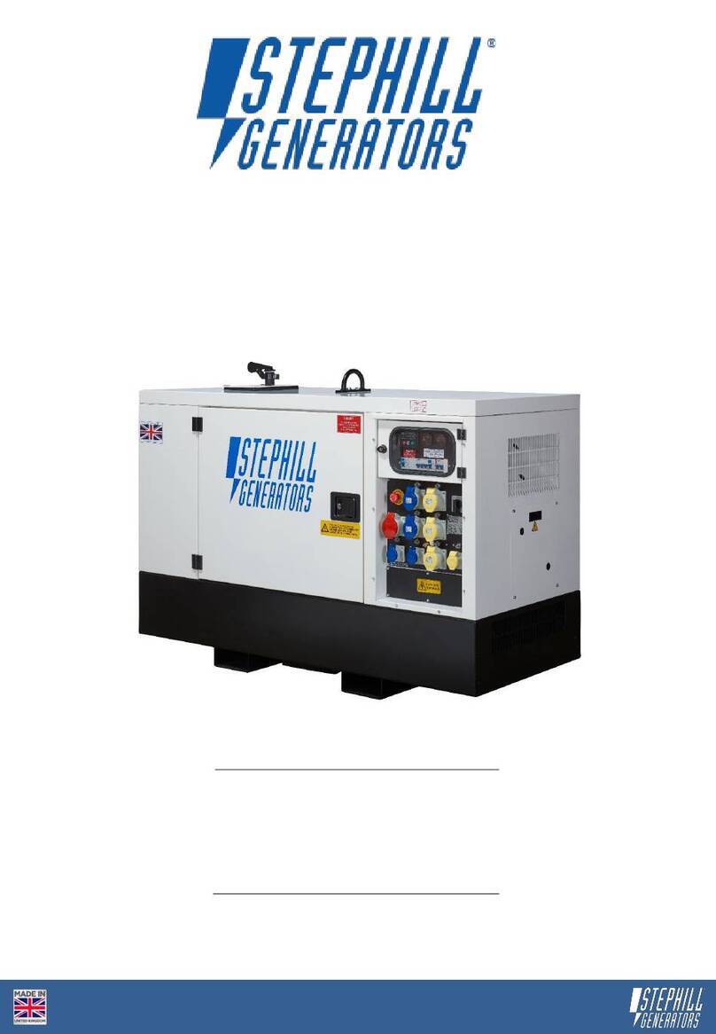
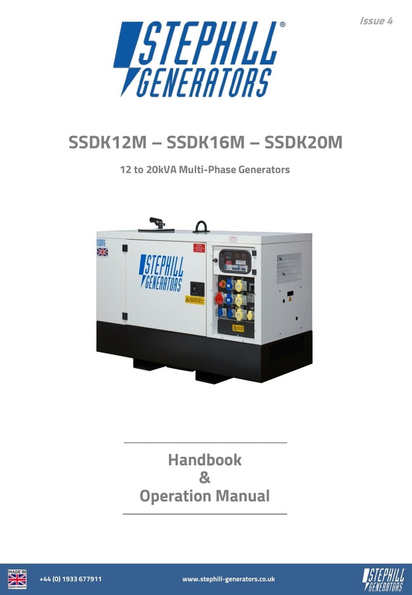
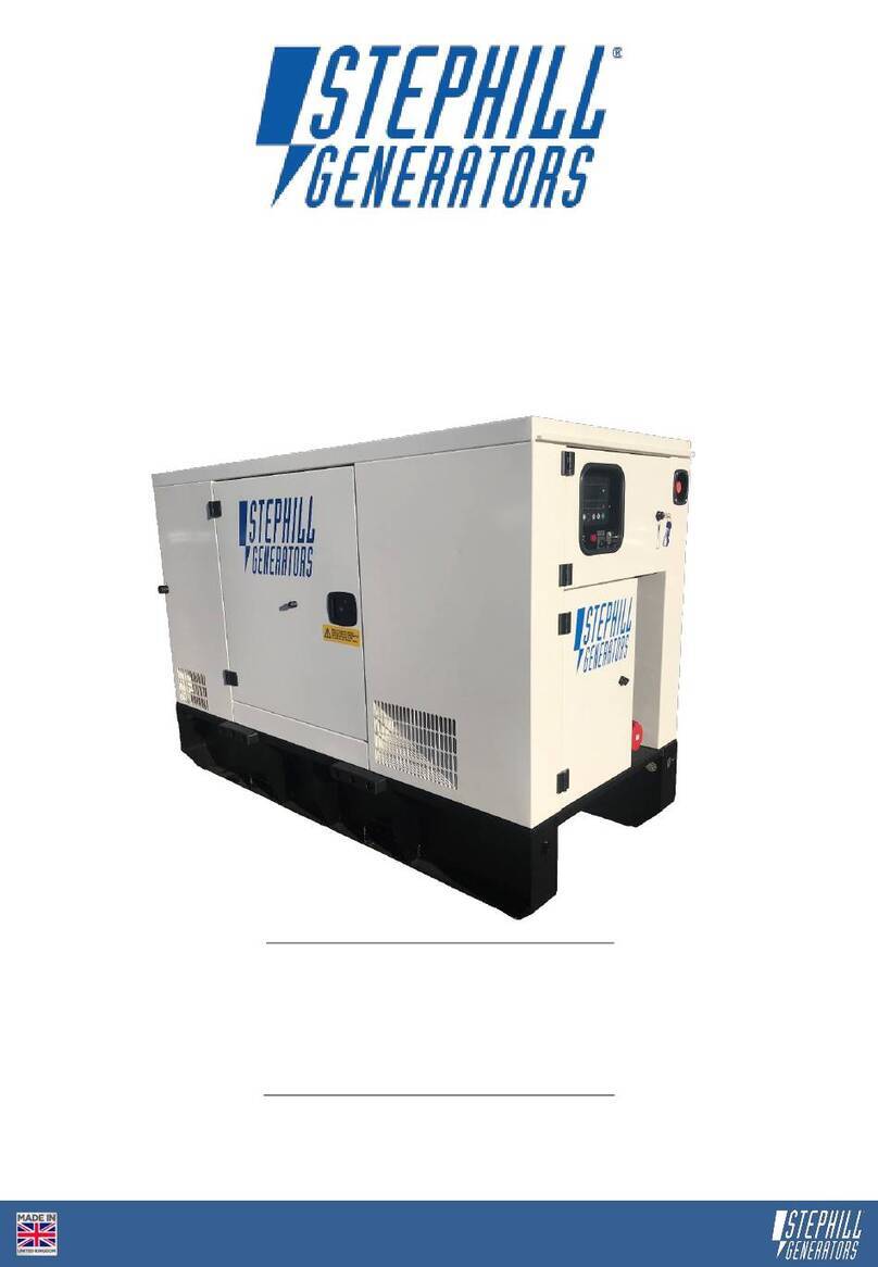
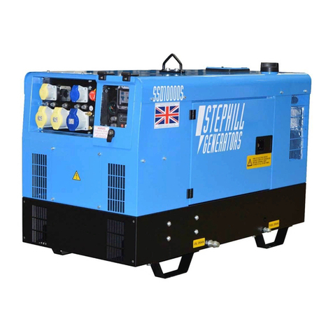
Stephill SSD10000S User manual

Issue 4
SSD10000S –SSD10000S/3PH
+44 (0) 1933 677911 www.stephill-generators.co.uk
Handbook
&
Operation Manual
10.0kVA 3000rpm Generators

SSD10000S - SSD10000S/3PH
3 Introduction
12 Operating Instructions
12 Pre-starts Checks
3 Warranty Statement 12 Check Battery Isolator Key & Location
13 Check Oil Level - How to
3 Amendments 13 Adding Engine Oil
14 Check Coolant Level
4 Identification 14 Check Fuel Level
14 Control Panel Checks
5 Specification
5 AC Output Protection - SSD10000S 15 Starting the Generator - Quick Start
5 AC Output Protection - SSD10000S/3Ph
5 AC Output Earthing Method 15 Manual Start
5 Running Hours 15 Applying Load
6 Engine
6 AC Alternator
6 Dimensions & Weights 15 Emergency Stop
15 Remote Start/Stop - 2-wire
7 Control Panel Identification
7 SSD10000S
7 SSD10000S/3Ph
16 DSE 3110 Control Module - Overview
8 Generator Safety 16 DSE 3110 Operation
8 Warning Signage 17 Starting Sequence
9 Personal Safety 17 Timer Icon
9 Auxiliary Power 17 Engine Running
9 Operating Environment 17 Viewing the Instruments
9 Temperature Range 17 AUTO MODE - Start/Stop Operation
10 Reference Relative Humidity 18 Waiting in AUTO MODE
10 Reference Barometric Pressure
10 Flammable Environment
18 Fault Finding
10 Saline Environment 18 Monitoring Systems
18 Before Fault Finding
10 Safety Considerations 18 Fault Finding - DSE 3110
10 General 22 Fault Finding - General
10 Fuel 23 Battery Charge Fault Finding Guide
10 Lubricating Oil
10 Safe Lifting
11 Earth Connections
11 Fumes
11 Noise
11 Battery Acid
11 Fire
11 Hot Parts
16 2-wire remote and ATS Auto
Start/Stop Connection Location
Contents
15 Stopping the Generator - Manual
Stop
Guide

SSD10000S - SSD10000S/3PH
25 Service and Maintenance
25 Pre-service
25 Engine Service
25 Alternator Service
26 Trolley Kit
26 Wheels
26 Maintenace
26 Road Tow Trailer
26 Trailer Information
27 Safety Precautions
27 Wheels
27 Number Plate
27 Hitch Type
27 Pre-towing/Hitch Up
27 Hitching Method
28 Spares
28 Kubota Consumable Service Spares
28 Control Panel - AC Components - SSD10000S
29 Control Panel - AC Components - SSD10000S/3Ph
29 Control Panel - DC Components
29 General Spares
29 Engine Accessories Spares
30 Exhaust System Spares
30 Trolley Kit Spares
31 Exploded View
Canopy Parts
Wiring Diagrams

SSD10000S - SSD10000S/3PH 3
© Stephill Generators Ltd.
All rights reserved.
Operation with incorrect fuel, lubricating oil or coolant.
Improper repair or use of parts not supplied or approved by Stephill Generators Ltd.
Lack of, or incorrect maintenance.
Issue Date By
Introduction
Warranty Statement
Amendments
This document has been produced for the owner/user of a Stephill generator. Inside this manual you will find
important safety, operating, maintenance and fault finding information.
The information contained within this manual is based upon the current data available before print. Due to
constant improvements on our products some information contained within this manual may change without
warning. Therefore Stephill Generators Ltd reserve the right to alter specifications as and when situations
demand without warning or obligation.
No part of this material may be reproduced in any form by any means without the written permission of
Stephill Generators Ltd.
All equipment supplied by Stephill Generators Ltd carries a warranty of 12 months from date of despatch.
During the warranty period, should the plant fail due to faulty design, materials or workmanship by Stephill
Generators Ltd or it’s sub-contractors, we undertake to rectify the fault. Stephill Generators Ltd will accept no
responsibility whatsoever for equipment that has failed due to;
Fair wear and tear, misuse, negligence, accidental damage, improper storage and incorrect starting / warm-
up / run-in or shutdown.
No warranty claim will be considered by Stephill Generators Ltd unless any defective parts are available for
inspection by us, or our nominees, to determine the reason or cause of failure, and Stephill Generators Ltd is
given the option of repair or replacement.
Stephill Generators Ltd are not responsible for incidental or consequential damages, downtime, or other
costs due to warrantable failure, and unauthorised alterations made to any product supplied by Stephill
Generators Ltd.
Amendment

SSD10000S - SSD10000S/3PH 4
Fig.1
1Generator model type
2Rated power, kVA & kW
3Unique serial number
5AC voltage output(s)
6Relevant maximum Amp ratings
7Rated output frequency
8Number of phases
9Power factor
10 Total fuel tank capacity
11 Generator performance class
12 MGW - Mass Gross Weight(s)
Each Stephill generator will have a Serial/Data plate fitted to the set. In most cases this can be found on the
canopy roof of a SSD10000S. Below is an example of the Serial/Data plate.
Identification
Item No.
Description
4
CE mark indicates the generator meets the directives listed on the Declaration of
Conformity
7
9
1
5
2
3
4
6
8
10
11
12

SSD10000S - SSD10000S/3PH 5
Main alternator 115/230V AC outputs protected by double pole MCB.
115V - Floating Earth - Thermal reset button overload protection for each socket.
Main outputs 400V/230V protected by an RCBO.
Note
MCB = Miniature Circuit Breaker (overcurrent)
RCD = Residual Current Device
RCBO = Residual Current Device with Overcurrent Protection
All are suitably rated for the generator model type.
400V 3Ph - Neutral (star point) bonded to earth.
230V 1Ph - Neutral bonded to earth.
115V 1Ph - Floating earth.
50% Load
75% Load
100% Load
10.0
10.0
AC Output & Protection - SSD10000S/3PH
(COP) Continuous Power: Applicable for supplying power to electrical load for unlimited hours in accordance
with ISO 8528-1 under the agreed operating conditions with the maintenance intervals and procedures being
carried out as prescribed by the manufacturers.
Specification
kVA (COP)
Fuel Tank Capacity
Model Type
SSD10000S
SSD10000S/3PH
kW (COP)
Frequency
AC Output Earthing Method
Running Hours
13 hours @ 2.8 L/h
10 hours @ 3.7 L/h
25% Load
Voltage
Phase
LWA
dBA @ 7M
67
1 Ph
3 Ph
92
67
92
115 / 230V AC
400V AC
8.0
50.0 Hz
8.0
50.0 Hz
37 Litres
41 hours @ 0.9 L/h
20 hours @ 1.8 L/h
AC Output & Protection - SSD10000S
230V - Neutral bonded to Earth - RCD protection & thermal reset button overload protection for
each socket.

SSD10000S - SSD10000S/3PH 6
Type
Emissions Certification
Cylinders
Cooling
Displacement
Rpm
Type
Skid Mounted
Weight - Dry
Weight - Wet
Trolley Mounted
Weight - Dry
Weight - Wet
Road Trailer Mounted
Weight - Dry
Weight - Wet
Length 2360mm Width 1300mm Height 1220mm
399 KG
330 KG
301 KG
388 KG
386 KG
AC Alternator
Length 1750mm Width 900mm Height 1080mm
357 KG
355 KG
Water Cooled
Engine
Net Engine Power
Kubota D722-E4B
SSD10000S/3PH
3
EU Stage V
Net Intermittent
719cc
3000
SSD10000S
SSD10000S/3PH
299 KG
Dimensions & Weights
430 KG
428 KG
397 KG
Continuous 10.3kWm
Length 1285mm Width 655mm Height 900mm
NSM Z100 LB
SSD10000S
NSM C112 SB
332 KG

SSD10000S - SSD10000S/3PH 7
Fig.2
1AC Voltage Switch
2Emergency Stop
3Fuel Gauge
4Main MCB & 230V RCD
5115V Socket Outlets (Yellow)
6Socket Outlet Reset Button(s)
7230v Socket Outlets (Blue)
8Earth Stud
9Fuel Pump Prime Button
10 DSE 3110 Reset Buttons
11 DSE 3110 Control Module
1400V Socket Outlet (Red)
2230V Socket Outlet (Blue)
3Emergency Stop
4Fuel Pump Prime Button
5Main RCBO
6Earth Stud
7Fuel Gauge
8DSE 3110 Reset Buttons
9DSE 3110 Control Module
Fig.3
Control Panel Identification
SSD10000S/3PH
Item No.
Description
SSD10000S
Item No.
Description
5
3
4
2
6
11
8
7
1
9
10
5
1
2
6
7
9
4
8
3

SSD10000S - SSD10000S/3PH 8
Warning Signage
b) Located on both main canopy doors.
a) Located behind the control panel cover near the DSE
3110 control module.
c) Located on the engine end of the canopy
near the exhaust outlet.
d) Located on top of the canopy near the
coolant filler flap for the radiator access.
e) Located on the canopy roof near the
control panel.
Generator Safety
Before using this equipment and to avoid personal injury, all warnings shown on the machine should be
observed. The warning signage should be checked for legibility and any that have become damaged should be
replaced.
Carefully read and understand the instructions provided. If there is anything you do not understand DO NOT
attempt to use this generator. Contact your supplier for advice.
WARNING
BEFORE STARTING
●READ HANDBOOK AND SAFETY ADVICE
●CHECK OIL LEVEL
●DO NOT ADJUST ENGINE SPEED
WITHOUT SUITABLE TEST EQUIPMENT
a)
b)
c)
d)
e)
f)

SSD10000S - SSD10000S/3PH 9
f) Located on the control panel door/cover.
• Do not climb on the generator - dents may cause overheating of the acoustic lining.
• Keep well clear of any moving parts on the generator at all times.
• Keep children and pets away from the generator and operating area.
• Test safety features often, emergency stop button and RCD (residual current device).
• Keep the generator canopy doors shut while running and locked if possible.
Do not remove covers and attempt to work on the generator while the engine is running.
Check the rating and electrical safety of the load before connecting the generator.
Equipment should never be connected that in total exceeds the specified rating of the generator.
• Do not cover the generator as this can obstruct air inlet and outlets on the canopy which can cause the
generator to overheat and cause permanent damage..
The electricity produced by an engine driven generator is very similar to mains AC electricity and should be
treated accordingly.
g) Located on the canopy roof near the
control panel.
Installation of the generator as a standby or secondary power source should only be undertaken by a fully
qualified electrician using the appropriate means of isolation from the mains supply. Installation must comply
with all applicable laws, electrical codes and wiring regulations.
The generator should always be operated on level ground and be able to bear its weight. Ensure the
generator canopy is not obstructed to allow cool air to enter the set and hot expelled air to escape.
Temperature Range
Auxiliary Power
Operating Environment
Personal Safety
A temperature range between -15⁰C and +45⁰C are the normal limits of operation. Operating outside the
range will require additional modifications.
f)
g)

SSD10000S - SSD10000S/3PH 10
Stephill generators must not be used in a flammable environment.
Operation of the machine in a saline environment will require additional corrosion protection.
All Stephill generators comply with current EEC directives including:
2016/1628/EU Non-Road Mobile Machinery (NRMM).
2014/30/EU The Electromagnetic Compatibility Directive.
2006/42/EC The Machinery Directive.
2000/14/EC Noise emission in the environment by equipment for use outdoors.
2011/65/EU The Restriction of Hazardous Substances Directive.
EC 1907/2006 REACH.
Reference Relative Humidity
General
Safety Considerations
Fuel
Reference Barometric Pressure
Saline Environment
The standard reference condition for relative humidity is 30%. Above this value the rated power must be
reduced.
New oil presents no hazard following short term exposure. Lubricants in particular used engine oil,
are potentially carcinogenic. Direct contact should always be avoided by wearing suitable rubber
gloves when handling them. Used oil should not be allowed to contact the skin. If this does occur,
wash off quickly with a proprietary hand cleanser.
Lubricating Oil
Safe Lifting
The standard reference condition for total barometric pressure is 1 bar. This corresponds to an altitude of
approximately 100m. Above 100m the rated power must be reduced.
Where mechanical assistance is used in lifting machines, ensure the lifting eye is used, and that all
components used to lift the machine are within their Safe Working Load (SWL).
The integral lifting beam and associated lifting eye on the generator should be regularly checked for signs of
damage or gross corrosion.
All nuts and bolts associated with the lifting beam and eye should be regularly checked for tightness and
corrosion.
Fuels and lubricants are a potential source of fire. Be careful not to spill fuel, clean up any spillages.
Inhalation or swallowing of diesel should be avoided. If in doubt seek medical advice. All other forms of
contact are an irritant and therefore should also be avoided. If skin contact is made wash with soap and
water.
Flammable Environment

SSD10000S - SSD10000S/3PH 11
This is corrosive and irritant by all forms of exposure. If skin contact is made wash with clean water.
Battery Acid
Earth Connection
DO NOT ATTEMPT TO LIFT THE GENERATOR WITHOUT PRIOR CHECKS TO THE LIFTING
SYSTEM AS INDICATED ABOVE
Lifting equipment should never be attached directly to the engine and/or alternator to fully lift the generator
except only if lifting engine and/or alternator.
Make sure that the Generator is at least 2 metres away from any building during operation. Operate in a well
ventilated unconfined area, so that fumes can be properly dispersed. Silencer outlet should be facing an open
area to prevent fumes being recirculated. There is the danger of asphyxiation due to exhaust gases.
Inhalation of poisonous exhaust fumes can lead to serious injury or death. The generator must not be used in
a poorly ventilated or enclosed area.
Ear protection may be required depending on the combined noise level of the Generator, auxiliary load and
the operator’s distance from it and the length of exposure. (Noise at Work Regulations 1989)
Ensure that suitable fire extinguishers (AFFF or CO2) are kept within close proximity of the generator. Do not
cover, enclose, or obstruct the airflow to the generator during or shortly after use, due to fire hazard or
damage to the generator from overheating. Allow the generator to cool after use before storing away. Keep
all inflammable objects clear of the generator.
There is the danger of burns as parts of the generator will become very hot during use. No part of the engine,
alternator or exhaust must be touched during or shortly after operation. Do not operate the generator unless
all guards are in place. There is a risk of burns or serious mechanical injury.
All Stephill products are fitted with an earth stud on the control panel this must be connected to an earthing
system or spike. Any earth spike required is dependant on the local conditions of use. The size is determined
by reference to current IEE regulations or to a competent electrician.
Fire
Hot Parts
Fumes
Noise

SSD10000S - SSD10000S/3PH 12
Before any attempt to start the generator please follow these important guidelines.
Isolator key location
(This is currently shown in the "OFF" position) Fig.4
To switch OFF the 12V battery supply, push down and turn the red key counter-clockwise to release .
Check Battery Isolator Key - Location
STEPHILL GENERATORS LTD STRESS THAT THE ULTIMATE RESPONSIBILTY FOR THE
SAFE USE OF THE GENERATOR RESTS WITH THE USER.
Open the main canopy door on the right when facing the control panel. The RED isolator key can be found
next to the in-line fuel filter - Fig.4
To switch ON the 12V battery supply, insert the red key and turn to lock into position.
Operating Instructions
Pre-start Checks
The 12V battery supply has been fitted with a red "Battery Isolator Key". This is to isolate the 12V battery
from the engines 12V DC system when not in use, transportation and when working on repairs/servicing
safely.
Engine
In-line Fuel Filter
Battery Isolator Key
Oil Drain Hose

SSD10000S - SSD10000S/3PH 13
It is recommended to check the oil level BEFORE EVERY START OPERATION - Ref. Fig.5
Ensure the generator (engine) is on level ground to ensure the correct oil quantity is measured.
● Check the engine oil level before starting or more than 5 minutes after stopping the engine.
● Remove the oil level gauge, wipe it clean and reinstall it.
● Take the oil level gauge out again, and check the oil level.
(1) Oil filler plug
(2) Oil level gauge (A) Ensure the engine oil level within this range
Fig.5
Adding Engine Oil
Refer to engine owners handbook supplied with each generator for oil specification, viscosity and typical
capacity. Alternatively navigate to the Service section at
Check Oil Level - How To
Fig.5 shows the oil fill and oil dipstick locations for the Kubota D722 engine used on the Stephill SSD10000S
generators.
Add oil If the level is low. Do fill past the high mark on the dipstick (2). WARNING - Never overfill the engine
with oil. Engine damage can occur.
www.stephill-generators.co.uk

SSD10000S - SSD10000S/3PH 14
Refer to engine owners handbook supplied with each generator for further information.
(A) "FULL"
(B) "LOW"
While holding down the fuel pump prime button you should be able to see the gauge needle rise and rest to
indicate a level, also you should hear the fuel pump operating.
The radiator is provided with a recovery tank (expansion vessel) , check the water/coolant is between the
"FULL" and "LOW" marks - Ref. Fig.6.
While the generator is at standstill you will notice the fuel gauge on the control panel will be showing empty
"no fuel".
Fig.6
Check Coolant Level
(1) Recovery tank
(expansion vessel)
Ensure the main MCB or RCBO is in the "OFF" position (switch down) - Ref Fig.2 & 3. WARNING - Never try to
start the generator with load connected.
It is recommended to check the water/coolant level of the radiator BEFORE EVERY START OPERATION - Ref.
Fig.6.
Check Fuel Level
Control Panel Checks
To check the fuel level in the generator fuel tank you can energise the fuel gauge by pressing and holding the
fuel pump prime button on the control panel - see Fig.2 & 3.

SSD10000S - SSD10000S/3PH 15
Once all the pre-checks have been made you can then start the generator. Follow the procedure below:
Press the button until the is displayed on the LCD screen.
A red LED flashes above the button.
Now the generator is ready to receive load. Select the desired AC voltage with the AC voltage switch.
Plug the load into the relevant AC voltage socket on the control panel.
Switch the main MCB to "ON" (switch up) position on the control panel.
You can then safely stop the generator.
Press the button and the generator will immediately stop.
Starting the Generator - Quick Start Guide
The DSE 3110 control module has a 2-wire Remote Start/Stop function. This is a volt free connection, closing
two contacts will start and allow the generator to run. Open the contacts and the generator will stop and the
DSE 3110 module will wait for the next start request.
Stopping the Generator - Manual Stop
Remote Start/Stop - 2-wire
The Emergency Stop button is located on the control panel. It must ONLY be used for emergencies
only.
Emergency Stop
Warning Using the Emergency Stop button regularly for a standard stop request can cause the 12V battery to
drain. This may effect the starting of the generator.
Manual Start
This is a quick start guide , refer to the DSE 3110 Control Module - Overview within this handbook for an in-
depth view/use of the DSE 3110 control module.
The icon will be displayed on the DSE 3110 module when an Emergency Stop request is
made.
Press the button once more, the icon rotating will be displayed on
the LCD screen. This will continue to rotate for approximately 10 seconds.
The generator will then crank and start.
Before stopping the generator it is recommended to switch off the load from the generator by switching the
main MCB on the control panel to the "OFF" position (switch down).
Applying Load

SSD10000S - SSD10000S/3PH 16
Fig.8
Fig.9 Fig.10
Once the correct connections have been made to the remote start terminals the DSE 3110 control module
will require activating to an AUTO MODE - See DSE 3110 Control Module - Overview . It will then be ready to
accept a remote start request.
2-Wire Remote and ATS Auto Start/Stop Connection Location
Behind the control panel there is a small push-on connector block for the remote and auto start/stop
connections. Refer to the DC wiring diagram at the back of this handbook or corresponding ATS handbook for
the relative terminal positions. - Fig.7 & 8.
DSE 3110 Operation
The DSE 3110 control module is used to start/stop and monitor key elements of the engine and main AC
alternator. Fig.9 show the layout and control buttons.
DSE 3110 Control Module - Overview
Engine Speed
Generator Volts (AC)
Generator Frequency
Engine Run Time
Battery Volts (DC)
Page Order

SSD10000S - SSD10000S/3PH 17
Once a start request is made the DSE 3110 will energise the pre-heat relay over a period of 10 seconds.
Once the engine is running and all starting timers have expired, the animated icon is displayed.
Fig.10 shows the page order when pressing the navigation button.
A red LED light will be illuminated above the button.
The generator is now ready to receive start/stop requests from the remote connections.
When scrolling manually, the display will automatically return to the Status page if no buttons are pressed for
the duration of the LCD Page Timer.
If the engine fails to fire during this cranking attempt then the starter motor is disengaged for the crank rest
duration after which the next start attempt is made.
Starting Sequence
Then the DSE 3110 will then attempt to crank the engine by operating the starter motor relay and also the
fuel pump relay.
Should this sequence continue beyond 3 attempts, the start sequence will be terminated and the Failed to
Start icon is displayed on the LCD screen.
(See Fault Finding - DSE 3110)
Timer Icon
Timer Icon
When the engine fires, the starter motor is disengaged. (The DSE 3110 de-energises the starter motor relay
once it detects an output frequency (Hz) from the main alternator).
It is possible to scroll to display the different pages of information by repeatedly operating the navigation
button.
Engine Running
AUTO MODE - Start/Stop Operation
Engine Running
Viewing the Instruments
Activate auto mode by pressing the button. The icon will be displayed on the LCD screen to
indicate the DSE 3110 module is in AUTO MODE if no alarms are present.
When the module is controlling the engine (starting and stopping) an animated (rotating) timer icon will be
displayed in the icon area to indicate that a timer is active, for example cranking time, crank rest, stopping
Once selected the page will remain on the LCD display until the user selects a different page or after an
extended period of inactivity, the module will revert to the status display.
Failed to Start

SSD10000S - SSD10000S/3PH 18
cont.
● Check No.1 wires on the control panel and engine DC
loom(s) have a sound connection to battery negative.
Negative / Ground Connections
● Check the operation of the switches on the back of the
emergency stop button.
● Check the operation and wiring of the starter motor relay -
Replace if necessary.
Emergency Stop Button
Possible Cause
Be aware of the service/maintenance schedule of the engine, ensuring the fuel filters are replaced regularly
along with the oil topped up and oil filter etc. - See Service and Maintenance
Before carrying out any checks ensure all Load is unplugged from the generator and be aware of any
potential exposed Live terminals while the generator is running! All checks and tests should only be carried
out by a competent engineer - Ref. DC wiring diagram
Starter Motor Relay
Check
Most common faults/issues can be Identified by the fault icon displayed on the DSE 3110 LCD screen. The
table below shows a fault icon and/or the relevant possible causes and checks.
It is advised to have a mains 12V battery charger fitted to the generator battery in most cases of occasional
use fixed positioned generators or ensure the generator is started and allowed to continuously run for a
minimum of 1 hour once a week.
Fail to Start
Is activated after
three attempts to
start
Battery
● Check the battery voltage, should be around 12.5V DC -
Charge or Replace.
● Check the condition of the battery leads.
STEPHILL GENERATORS LTD STRESS THAT THE ULTIMATE RESPONSIBILTY FOR THE
SAFE USE OF THE GENERATOR RESTS WITH THE USER.
All standard Stephill SSD10000S generators use a DSE 3110 control module to operate/monitor the engine
and generator.
While the DSE 3110 module is in AUTO MODE the LCD screen will be permanently illuminated and it will not
go into any power saving or sleep modes.
If the module is left in AUTO MODE for extended long periods of time without running the generator it could
flatten the generator battery.
Engine Not Starting/Running - Starter motor not engaging
Waiting in AUTO MODE
Fault Finding - DSE 3110
Fault Icon
Before Fault Finding
Fault Finding
Monitoring Systems
We strongly advise before attempting any fault finding is to check the health of the generator battery. It
should measure around 12.4 to 12.6 Volts DC while the generator is at standstill.

SSD10000S - SSD10000S/3PH 19
● Check and/or replace the main fuel filter.
● Check the connections on the capacitor.
● Test and/or replace the AC alternator capacitor.
The no-load frequency/rpm should measure approximately 52.5Hz/3150rpm.
● Check in-line fuel filter and replace if necessary.
● Check water separator filter if necessary.
● Check the condition of the air filter - Replace if necessary.
cont.
● Check the green plug with a brown & blue wire is not
loose.
● Start and run the generator and measure the AC voltage
across the brown & blue wires - this should measure
approximately 115V, 230V or 400V AC.
DSE 3110 Control Module
Low AC Voltage
● Check the switches function and wiring on the back of the
emergency stop.
Emergency Stop
Fuel Filter(s)
Air Filter
● Check main alternator output - AC alternator tests would
be advisable.
● Check in-line fuel filter and replace if necessary.
● Check the 40A fuse on the engine loom - Ref. wiring
diagram.
Fuel Filter(s)
● Check the plugs on the back of DSE 3110.
Starter Motor
Capacitor
DSE 3110 Control Module
● Check for battery + output at No.4 (starter motor relay
feed) after the pre-heat time - Ref. wiring diagram.
● Check the operation and wiring of the starter motor -
Replace if necessary.
Engine Not Starting/Running - Starter motor engaging but engine not starting
● Check for continuity and wiring on the AC 2A reset button
(brown wire from DSE 3110) - Replace if necessary.
2A Reset Button
Low AC Voltage and Low Hz/Frequency could indicate the engine is running too slow.
Warning - It is not recommended to adjust the engine speed unless absolutely
necessary.
Main AC Alternator
● Check the fuel pump is receiving 12V DC and is operating -
Replace if necessary.
● Check the condition of the air filter - Replace if necessary.
● If possible run the generator from a separate fuel source
from the fuel tank.
Engine Starting/Running Then Stopping - 3 Attempts
Fuse
Fault Icon
Possible Cause
Low Hz/Frequency
Shutdown
Check
Contaminated Fuel
Fuel Lift Pump (12V DC)
Fuel Lift Pump (12V DC)
● Check that all the green plugs are fitted correctly and the
wiring.
DSE 3110 Control Module
● If possible run the generator from a separate fuel source
from the fuel tank.
● Check the fuel pump is receiving 12V DC and is operating -
Replace if necessary.
Fail to Start
Is activated after
three attempts to
start
Shutdown
Consult an engine specialist if the above fails to rectify the issue.
Consult an engine specialist if the above fails to rectify the issue.
Emergency Stop Button
Air Filter
Contaminated Fuel
DSE 3110 not showing Volts or Hz when running?
● Check if the emergency stop button has been activated.
This manual suits for next models
1
Table of contents
Other Stephill Portable Generator manuals
Popular Portable Generator manuals by other brands
Advance Power
Advance Power AP3000 Operating and maintenance instructions
RVMP
RVMP Flex Power 5000i owner's manual
North Star
North Star 15000 PPG owner's manual
Matsusada Precision
Matsusada Precision PKTS Series instruction manual
Yamaha
Yamaha EF2400iS - Inverter Generator owner's manual
CAC / BDP
CAC / BDP FOR BYPASS AND FAN POWERED HUMIDIFIERS Diagnostic repair manual
