Steris AMSCO RELIANCE 430 User manual

UNCRATING/INSTALLATION INSTRUCTIONS
AMSCO®RELIANCE® 430
Single-Chamber Washer/Disinfector
(09/15/00) P-122990-172
Rev. 5

LIMITATIONS OF LIABILITY AND INDEMNITY
IN NO CASE, WHETHER AS A RESULT OF A BREACH OF CONTRACT, BREACH OF WAR-
RANTY OR TORT (INCLUDING STERIS'S OR CUSTOMER'S WILLFUL ACTS OR NEGLIGENCE
OR STRICT LIABILITY) SHALL STERIS OR CUSTOMER BE LIABLE TO THE OTHER FOR ANY
CONSEQUENTIAL OR INCIDENTAL DAMAGES INCURRED BY THE OTHER, INCLUDING, BUT
NOT LIMITED TO, LOSS OF REVENUE, PROFITS OR GOODWILL. HOWEVER, NOTHING
CONTAINED IN THIS AGREEMENT IS INTENDED TO RELIEVE EITHER STERIS OR CUS-
TOMER FROM CLAIMS, LIABILITY, DAMAGES OR EXPENSES RESULTING FROM BODILY
INJURY, INCLUDING DEATH, OR FROM PROPERTY DAMAGE INCURRED DUE TO THE
WILLFUL ACTS, THE NEGLIGENCE OF OR THE STRICT LIABILITY OF THAT PARTY.
STERIS AGREES TO DEFEND, INDEMNIFY AND HOLD CUSTOMER HARMLESS FROM ANY
AND ALL CLAIMS, LIABILITY, DAMAGES OR EXPENSES DUE TO PERSONAL INJURIES,
INCLUDING DEATH, TO EMPLOYEES OF STERIS AND CUSTOMER AND TO THIRD PARTIES
AND FOR PROPERTY DAMAGE TO THE EXTENT OF THE WILLFUL ACTS OF THE NEGLI-
GENCE OF STERIS OR THE STRICT LIABILITY OF STERIS CAUSED BY THE ACTS OR
OMISSIONS OF STERIS. CUSTOMER AGREES TO DEFEND, INDEMNIFY AND HOLD STERIS
HARMLESS FROM ANY AND ALL CLAIMS, LIABILITY, DAMAGES OR EXPENSES DUE TO
PERSONAL INJURIES, INCLUDING DEATH, TO EMPLOYEES OF CUSTOMER AND STERIS
ANDTOTHIRDPARTIESANDFROMPROPERTYDAMAGETOTHEEXTENTOFTHEWILLFUL
ACTS OR THE NEGLIGENCE OF CUSTOMER OR THE STRICT LIABILITY OF CUSTOMER
CAUSED BY THE ACTS OR OMISSIONS OF CUSTOMER.
WARNING - COPYING PROHIBITED
This manual is protected by Federal Copyright Law, which
provides for damages of up to $20,000, as well as
criminal fines and imprisonment, for unauthorized copying.
i
Table of Contents Uncrating/InstallationInstructions 122990-172
Follow each step of the uncrating/installation instructions in the
order presented.Openthe carton carefullyto avoid damageto
the equipment inside. If you find any indication of damage to the
equipment (no matter how slight), show it to your supervisor.
To properly install this unit, you will need the Equipment Drawings
(previouslyfurnished),showingallutilityserviceandspacerequire-
ments.Ifdrawingscannotbelocated,replacement copiesmaybe
obtainedbywriting, faxing,ortelephoningSTERIS,givingtheserial
and model numbers of your equipment.
Onceinstalled,equipmentoperationshouldbetestedbyaqualified
service technician prior to your usage of the equipment.
If STERIS supervision is desired for installing and starting up this
equipment, contact your local STERIS representative.
TheAmsco®Reliance®430Single-Chamber Washer/Disinfector is
indicatedforuseinthecleaningandlow-leveldisinfectionofsoiled
reusable utensils, trays, glassware, bedpans and urinals, rubber
andplasticgoods,simplehard-surfacedrigidsurgicalinstruments,
suchasforceps,andclamps,andothersimilarandrelatedarticles
found in health care facilities.
STERISdoesnotintend,recommendnorrepresentinanywaythat
this Amsco Reliance 430 Single-Chamber Washer/Disinfector be
used for the terminal disinfection or sterilization of any regulated
medical device. Amsco Reliance 430 Single-Chamber Washer/
Disinfectors are intended only to perform an initial step in the
reprocessing of soiled, reusable medical devices. If medical de-
vices will be contacting blood or compromised tissues, such
devices must be terminally processed in accordance with good
Hospital Practices before each use in human patients.
A thorough preventive maintenance program is essential to safe
and proper equipment operation. You are encouraged to contact
your STERIS reprsentative concerning extended service mainte-
nanceagreementstogiveyourwasher/disinfectorplannedmainte-
nance, assuring equipment performance according to factory
specifications.STERISmaintainsanationwidestaffofwell-equipped,
factory-trainedtechnicianstoprovidethisservice,aswellasexpert
repairservices.PleasecontactyourlocalSTERISrepresentativefor
service details.
STERIS carries a complete line of accessories for use in this
equipment. A STERIS representative will gladly review these
with you.
©2000- STERIS Corporation. All rights reserved. Printed in Canada
A WORD FROM STERIS
Indications For Use
12345678901234567890123456789012123456789012345678901234567
1
234567890123456789012345678901212345678901234567890123456
7
12345678901234567890123456789012123456789012345678901234567
12345678901234567890123456789012123456789012345678901234567
1
234567890123456789012345678901212345678901234567890123456
7
12345678901234567890123456789012123456789012345678901234567
Service Information
12345678901234567890123456789012123456789012345678901234567
1
234567890123456789012345678901212345678901234567890123456
7
12345678901234567890123456789012123456789012345678901234567
12345678901234567890123456789012123456789012345678901234567
1
234567890123456789012345678901212345678901234567890123456
7
12345678901234567890123456789012123456789012345678901234567
Advisory
12345678901234567890123456789012123456789012345678901234567
1
234567890123456789012345678901212345678901234567890123456
7
12345678901234567890123456789012123456789012345678901234567
12345678901234567890123456789012123456789012345678901234567
1
234567890123456789012345678901212345678901234567890123456
7
12345678901234567890123456789012123456789012345678901234567

ii
122990-172 Uncrating/InstallationInstructions Table of Contents
SalesSales
SalesSales
Sales Direct Technical AssistanceDirect Technical Assistance
Direct Technical AssistanceDirect Technical Assistance
Direct Technical Assistance
STERIS Corporation STERIS Field Engineering
5960, Heisley Road 2424, West 23rd Street,
Mentor, Ohio 44060-1834 Erie, PA 16506
Tel.: 440 354 2600 Tel.: 814 452 3100
Fax: 440 639 8199 Fax: 814 870 8400
ManufacturingPlantManufacturingPlant
ManufacturingPlantManufacturingPlant
ManufacturingPlant
STERIS Canada Corporation
415, rue des Alleghanys
Beauport (Quebec)
Canada G1C 4N4
Tel.: 418 664 1549
Fax: 418 664 0188
Web Site:Web Site:
Web Site:Web Site:
Web Site:www.steris.com

iii
Table of Contents Uncrating/InstallationInstructions 122990-172
1 LISTING OF WARNINGS, CAUTIONS AND
SYMBOLS....................................................... 1-1
2 UNCRATING INSTRUCTIONS ........................2-1
Open the Crate ........................................................ 2-1
Remove Crate and Packing ..................................... 2-1
Remove Base and Move Washer/Disinfector ........... 2-1
Prepare Washer/Disinfector for Installation .............. 2-2
3 INSTALLATION INSTRUCTIONS....................3-1
Before Installing Equipment ..................................... 3-1
Connect Utilities ....................................................... 3-1
Initial Set-up ............................................................. 3-2
Initial Set-up Test ..................................................... 3-3
4 OPERATIONAL TESTS ...................................4-1
First Operational Test............................................... 4-1
Second Operational Test ......................................... 4-2
TABLE OF CONTENTS
SECTIONSECTION
SECTIONSECTION
SECTION TITLETITLE
TITLETITLE
TITLE PAGEPAGE
PAGEPAGE
PAGE

1-1
122990-172Summary of Warnings and Cautions Uncrating/Installation Instructions
Thefollowingisalistingofsafetyprecautionswhichmustbeobservedwhenuncrating,installing,andcheckingthis
equipment. WARNINGS indicate the potential for danger to personnel and CAUTIONS indicate the potential for
damage to equipment. These precautions are repeated (in whole or in part), where applicable, throughout the
instructions.
WARNING - LACERATION/EYE INJURY HAZARD:
WHENREMOVINGBANDS,weareyeprotectionandalwaysuseatoolspecificallydesignedtocutthebands.
The bands used to secure this container can cause personal injury when cut and tension is released.
WARNING - PERSONAL INJURY AND/OR EQUIPMENT DAMAGE HAZARD:
WHEN MOVING WASHER/DISINFECTOR, use a forklift. Do not use the doors or door handles for lifting.
TO TILT THE WASHER/DISINFECTOR, more than one person is required. Washer/disinfector weighs
approximately 1000 lbs (454 kg).
WARNING - LACERATION HAZARD:
WHEN REMOVING BOLTS, wear gloves to protect your hands.
WARNING - BURN HAZARD:
WHENCHECKING AUTOMATICSTOP FEATURE, openchamberdoor slowly andweargloves and
face protection. Hot water/steam may be sprayed through door opening if door is opened while
washer is operating.
EXCEPTFORANEMERGENCY,donotopendoorwhencycleisinprogress.Inanemergency,firststopcycle
by pressing the STOP touch pad and wait for water flow to stop. Wear protective gloves and face shield
whenever reaching into the chamber.
WARNING - FALL HAZARD:
TO PREVENT FALLS, keep floor dry. Promptly clean up any spills or drippage.
WARNING - CHEMICAL BURN HAZARD:
WASHER/DISINFECTOR DETERGENTS ARE CAUSTIC and can cause adverse effects to exposed tissues.
Do not get in eyes, on skin or attempt to ingest by mouth.
•Read and follow the precautions and instructions on the detergent label and in the Material Safety Data
Sheet (MSDS) prior to handling the detergent, refilling the detergent container or servicing the detergent
injection pump and lines.
•Wear protective gloves, face shield and clothing whenever handling the detergent or servicing the
detergent injection pump and lines.
WARNING - ELECTRICAL SHOCK HAZARD:
FASTENERS AND STAR WASHERS ARE USED to ensure protective bonding continuity. Always re-
install any star washers which may have been removed during installation or servicing.
CAUTION - POSSIBLE EQUIPMENT DAMAGE:
Leave door closed to prevent counterweight from dropping to bottom of guiding box.
!
!
!
!
!
!
!
!
!
LISTING OF WARNINGS, CAUTIONS AND
SYMBOLS 1
!

1-2
122990-172 Summary of Warnings and CautionsUncrating/Installation Instructions
CAUTION (Cont'd)
Oncethree-phasepowerisconnected,checkpumpforcorrectrotation,indicatedbyarrowonpumpmotor.
Incorrect pump rotation may result in pump damage and improper washing action.
If unit must be tilted, tilt onto left or right side. Handles and control panels could be damaged if unit is tilted
onto front (soiled) or back (clean) side.
Avoid product damage. Always select a cycle appropriate for the items being processed.
Whenchoosingdetergent,selectonewithalowchloridecontent.Detergentswithahighchloridecontentmust
not be used, as chlorides will harm and deteriorate stainless steel.
IMPORTANT::
::
: Be sure to check the Occupational Health and Safety Act, as well as local electric and plumbing
codes, for any special requirements that may pertain to installation of this washer/disinfector.
!
!
!
!
Symbols Symbol Definition
Protective Earth (Ground)
Warning! Risk of Electrical Shock
Electrostatic Sensitive Device
This Way Up
Do Not Stack
Fragile
Keep Dry
A Amperage Rating of the Unit
VVoltage Rating of the Unit
~AlternatingCurrent
kW Power Rating of the Unit
Hz Frequency of the Unit
φφ
φφ
φPhase of the Unit

2-1
122990-172UncratingInstructions Installation/Uncrating Instructions
NOTE:
The equipment in this container weighs approximately
1100 lbs (500 kg). Use a forklift to move washer.
NOTE: Uncrate on level floor as close to the installation site as
possible.
1. Place crate in position to be opened from the top. Provide a
clear work area on all sides (see Figure 2-1).
2. Carefully cut and remove bands from container.
3. Discard bands before continuing.
1. Lift off top wooden panels.
2. Remove wooden side panels. Discard top and side panels.
3. Remove foam sheets.
4. Check tip indicator (located inside bottom service compart-
ment, see Figure 2-2). If unit has been tipped, notify the
STERIS Regional Office nearest you.
1. Openbottomservice compartment and removethefourlag
bolts holding washer to shipping base (see Figure 2-2).
2. Using a forklift, lift the washer from base. If washer is too high
to be lifted by forklift, proceed to step 6.
Figure 2-2. Remove Lag BoltsFigure 2-1. Position Crate
Top
Bands
Container
Nails
Lag
Bolts Tip Indicator
Wood Base
Lag Bolts
Remove Base and Move
Washer/Disinfector
12345678901234567890123456789012123456789012345678901234567
1
234567890123456789012345678901212345678901234567890123456
7
12345678901234567890123456789012123456789012345678901234567
12345678901234567890123456789012123456789012345678901234567
1
234567890123456789012345678901212345678901234567890123456
7
12345678901234567890123456789012123456789012345678901234567
Remove Crate
and Packing
12345678901234567890123456789012123456789012345678901234567
1
234567890123456789012345678901212345678901234567890123456
7
12345678901234567890123456789012123456789012345678901234567
12345678901234567890123456789012123456789012345678901234567
1
234567890123456789012345678901212345678901234567890123456
7
12345678901234567890123456789012123456789012345678901234567
WARNING - LACERATION HAZ-
ARD: When removing bolts, wear
gloves to protect your hands.
Open the Crate
12345678901234567890123456789012123456789012345678901234567
1
234567890123456789012345678901212345678901234567890123456
7
12345678901234567890123456789012123456789012345678901234567
12345678901234567890123456789012123456789012345678901234567
1
234567890123456789012345678901212345678901234567890123456
7
12345678901234567890123456789012123456789012345678901234567
WARNING - PERSONAL INJURY
AND/OR EQUIPMENT DAMAGE
HAZARD: When moving washer/
disinfector, use a forklift. Do not
use doors or door handles for
lifting.
WARNING - LACERATION/EYE
INJURY HAZARD: When remov-
ing bands, wear eye protection
and always use a tool specifically
designed to cut the bands. The
bands used to secure this con-
tainer can cause personal injury
when cut and tension is released.
UNCRATING INSTRUCTIONS 2
Installation/Uncrating Instructions
2-2
122990-172 UncratingInstructions
3. Pull out and discard the wooden base under the washer.
4. Move washer to installation site.
5. Lower the washer.
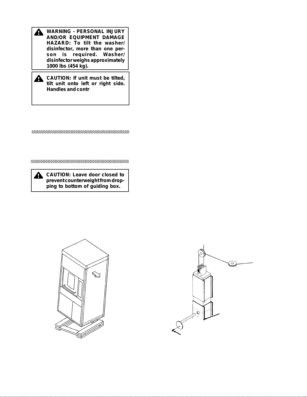
6. If washer is too high to be lifted by forklift, the washer may be
tilted (see Figure 2-3).
a. Place cardboard or removed foam sheets on skid to
protect cabinet.
b. Slowly tip washer sideways and lower onto skid, being
careful to prevent damage.
c. Move unit by forklift to its permanent site.
d. Carefully tip unit back to a standing position.
1. Remove all tape from washer/disinfector.
2. With door closed to prevent counterweight from dropping,
remove the door counterweight blocking pin as follows (see
Figure 2-4):
a. Removeboltsholdingleft(whenfacingfront[soiled]sideof
unit) side panel to washer.
b. Remove left side panel.
c. Remove screw from blocking pin. Keep screw.
d. Slide blocking pin out of counterweight box.
e. Once counterweight moves freely, fasten blocking pin
ontooutsideedgeofcounterweightbox,attachingscrew
previously removed through hole provided for pin stor-
age (see Figure 2-4). Pin may be needed for future door
maintenance work.
Figure 2-3. Tilt WasherFigure 2-3. Tilt Washer
Figure 2-3. Tilt WasherFigure 2-3. Tilt Washer
Figure 2-3. Tilt Washer Figure 2-4. Remove Blocking PinFigure 2-4. Remove Blocking Pin
Figure 2-4. Remove Blocking PinFigure 2-4. Remove Blocking Pin
Figure 2-4. Remove Blocking Pin
1
2
4
Blocking Pin For Blocking Pin
Storage
Screw
Prepare Washer/
Disinfector for
Installation
12345678901234567890123456789012123456789012345678901234567
1
234567890123456789012345678901212345678901234567890123456
7
12345678901234567890123456789012123456789012345678901234567
12345678901234567890123456789012123456789012345678901234567
1
234567890123456789012345678901212345678901234567890123456
7
12345678901234567890123456789012123456789012345678901234567
CAUTION: Leave door closed to
preventcounterweightfromdrop-
ping to bottom of guiding box.
WARNING - PERSONAL INJURY
AND/OR EQUIPMENT DAMAGE
HAZARD: To tilt the washer/
disinfector, more than one per-
son is required. Washer/
disinfectorweighsapproximately
1000 lbs (454 kg).
CAUTION: If unit must be tilted,
tilt unit onto left or right side.
Handlesandcontrolpanelscould
be damaged if unit is tilted onto
front(soiled)orback(clean)side.

2-3
122990-172UncratingInstructions Installation/Uncrating Instructions
f. Check that cables are seated in the pulley grooves (see
Figure 2-5).
g. Replace left side panel.
h. Repeat steps a. through g. for back (clean) side door.
3. Open chamber door. Remove nylon straps holding spray
headers to frame.
4. Remove nylon straps holding chamber spray arms.
5. Remove tape holding chamber filter.
6. Remove nylon straps and foam holding steam coils in the tub.
7. Remove tape and foam from pure water tank.
8. Remove all packing and tape from control panel.
9. Remove envelope containing Operator Manual and other
printed material. Give to appropriate personnel.
Figure 2-5. Door Cables and
Pulleys
Pulley
Cable
Counterweight
3-1
122990-172Installation Instructions Installation/Uncrating Instructions
1. Review permissible environmental conditions. This washer/
disinfectorisdesignedtogiveoptimalresultsinanenvironment
where maximum relative humidity is 80% for temperatures up
to 88°F (31°C) decreasing linearly to 50% relative humidity at
104°F (40°C).
a. Clearance-ClearancespaceshownonEquipmentDrawing
is necessary for easy installation and proper operation and
maintenance of washer/disinfector.
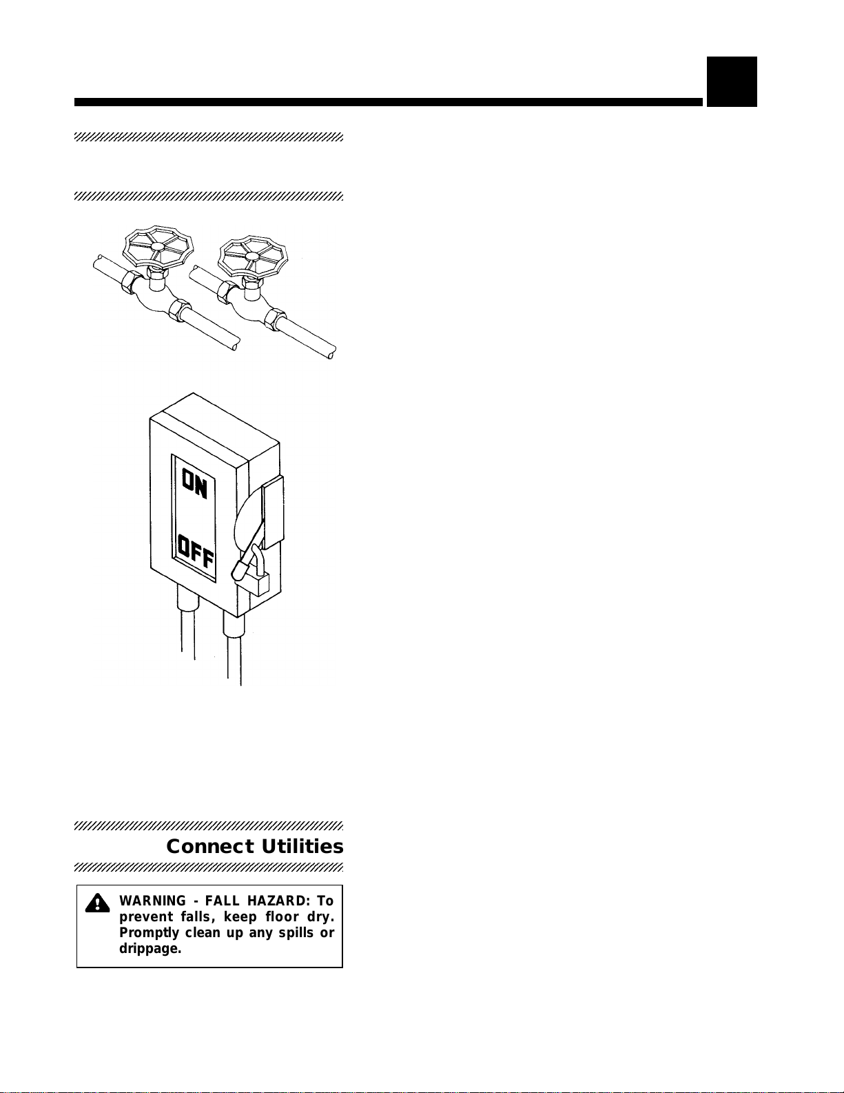
b. Utility service lines:
•Shutoff valves (not by STERIS) should be installed on
steam and water lines to washer/disinfector (see Figure
3-1). Shutoff valves allow washer/disinfector to be ser-
vicedwithoutshuttingoffbuildingsupply.Shutoffvalves
mustbecapableofbeinglockedinOFFposition.Vacuum
breakers are also recommended on water lines.
•Disconnectswitches(notbySTERIS)shouldbeinstalled
inelectric supplylines near washer/disinfector(see Fig-
ure 3-1). Disconnect switches should be capable of
being locked in OFF position only.
•If this machine is installed next to other equipment,
shutoff valves and disconnect switches should be lo-
cated so that service can be shut off to one piece of
equipment at a time.
•Utility service requirements are shown on Equipment
Drawing.Thismachinerequireseither208volts,3phase,
60 Hz (steam heated) or 480 volts, 3 phase, 60 Hz
(electric heated) power. Check Equipment Drawings or
name plate for proper voltage.
2. Place washer/disinfector, as shown on Equipment Drawing, in
correctrelation tobuilding supplylines. Ifunit is not at installa-
tion site, refer to Uncrating Instructions (Section 2) for proper
moving instructions.
NOTE:Floorunderwasher/disinfectorshouldbelevel.Ifnecessary,
adjustlevelinglegstolevelwasher/disinfector.Ifwasher/disinfector
is not level, water level control may not work properly.
3. Locate access door keys (inside chamber) and open rear
access doors.
1. COLDWATER-Blowoutthebuildingcold-watersupplylineto
remove chips, scale, etc. Connect line to washer/disinfector.
2. HOT WATER - Blow out the building hot-water supply line to
remove chips, scale, etc. Connect line to washer/disinfector.
3. STEAM - Blow out the building steam supply line to remove
chips, scale, etc. Connect line to washer/disinfector.
4. PURIFIEDWATER-Connectsupplylinetowasher/disinfector.
Figure 3-1. Utility Service
Connections
INSTALLATION INSTRUCTIONS 3
Before Installing
Equipment
12345678901234567890123456789012123456789012345678901234567
1
234567890123456789012345678901212345678901234567890123456
7
12345678901234567890123456789012123456789012345678901234567
12345678901234567890123456789012123456789012345678901234567
1
234567890123456789012345678901212345678901234567890123456
7
12345678901234567890123456789012123456789012345678901234567
Connect Utilities
12345678901234567890123456789012123456789012345678901234567
1
234567890123456789012345678901212345678901234567890123456
7
12345678901234567890123456789012123456789012345678901234567
12345678901234567890123456789012123456789012345678901234567
1
234567890123456789012345678901212345678901234567890123456
7
12345678901234567890123456789012123456789012345678901234567
WARNING - FALL HAZARD: To
prevent falls, keep floor dry.
Promptly clean up any spills or
drippage.

3-2
122990-172 Installation InstructionsInstallation/Uncrating Instructions
5. WASTE - Connect washer/disinfector drain line to building
waste line.
6. VENTILATION-Connectwasher/disinfectorventilationtobuild-
ing ventilation, as required.
7. Open building supply valves and check for leaks: correct if
necessary.
8. ELECTRIC - Connect building electrical supply to washer/
disinfector. Verify tight electrical connections.
Figure 3-2. Front (Soiled) Side
Control Panel Figure 3-3. Back (Clean) Side Control Panel

3-3
122990-172Installation Instructions Installation/Uncrating Instructions
NOTE:
Beforeoperatingthewasher/disinfector,aninitialset-uptest
shouldbeconductedbyaSTERISEngineeringServicetechnician
or equivalent person familiar with the operational test procedures,
including leak testing.
1. Open chamber door. Check that filters are positioned in wash
chamber bottom.
2. Remove manifold or accessory from chamber.
3. Checkthatnothinghasbeenleftinchamber(tapeortiewraps).
4. Close door and press POWER button. POWER light goes on
(see Figures 3-2 and 3-3).
5. Checkthatpurifiedwater storage tankbeginstofillas soon as
washer/disinfector is turned on. If not, contact a qualified
STERISEngineeringServicetechnician. Check that tankdoes
not overfill.
IMPORTANT: Do not use any detergent or lubricant for this test.
1. Select desired cycle by pressing the corresponding button
(INSTRUMENT, UTENSILS, RUBBER GOODS, PLASTIC
GOODS, or GLASSWARE).
NOTE: Washer/Disinfector operation can be halted at any time by
pressing STOP, waiting for water flow to stop, and then opening
door. Close door and press START to resume cycle. Pump opera-
tion will be delayed for 2 minutes after door is closed to avoid
chamber pressurization.
2. PressSTART.Letcycleruntoclearpipingsystemofanyforeign
matter.
NOTE:Lowdetergentandlubricantlevellightswillglow.Donotadd
any detergent or lubricant.
NOTE:Phasestatuslightsflashtoindicatewhichphaseisrunning,
showingcycleprogression(seeFigures3-2and3-3,andTable1).
3. Inspect piping for leaks. If necessary, tighten connections.
4. Check that CYCLE COMPLETE light turns on at end of cycle.
When cycle is complete, open door.
5. Remove and clean wash chamber filters. Replace filters in
chamber.
THIS COMPLETES THE INSTALLATION.Beforeoperating
the equipment, an operational test should be conducted by a
servicetechnician. ContactyourlocalSTERISsalesrepresentative
for availability and information on this service. Refer to the Mainte-
nance Manual (P-764327-734) for further details on these proce-
dures.
Initial Set-up Test
12345678901234567890123456789012123456789012345678901234567
12345678901234567890123456789012123456789012345678901234567
12345678901234567890123456789012123456789012345678901234567
1
234567890123456789012345678901212345678901234567890123456
7
12345678901234567890123456789012123456789012345678901234567
CAUTION: Avoid product dam-
age. Always select cycle appro-
priate for the items being pro-
cessed.
WARNING - BURN HAZARD: Ex-
cept for an emergency, do not
open door when cycle is in
progress. In an emergency, first
stopcyclebypressingtheSTOP
touchpadandwaitforwaterflow
to stop. Wear protective gloves
and face shield whenever reach-
ing into the chamber.
Initial Set-up
12345678901234567890123456789012123456789012345678901234567
1
234567890123456789012345678901212345678901234567890123456
7
12345678901234567890123456789012123456789012345678901234567
12345678901234567890123456789012123456789012345678901234567
1
234567890123456789012345678901212345678901234567890123456
7
12345678901234567890123456789012123456789012345678901234567

3-4
122990-172 Installation InstructionsInstallation/Uncrating Instructions
Table 3-1. AmscoTable 3-1. Amsco
Table 3-1. AmscoTable 3-1. Amsco
Table 3-1. Amsco®®
®®
®RelianceReliance
RelianceReliance
Reliance®®
®®
®430 Single-Chamber Washer/Disinfector Cycle Description Chart430 Single-Chamber Washer/Disinfector Cycle Description Chart
430 Single-Chamber Washer/Disinfector Cycle Description Chart430 Single-Chamber Washer/Disinfector Cycle Description Chart
430 Single-Chamber Washer/Disinfector Cycle Description Chart
COLD WATER
PRE-WASH DETERGENT
WASH RINSE 1 RINSE 2 PURE WATER
RINSE LUBRICATION DRY
Fixed Time
2 min. 4-8 min. 30 sec 60 sec
Temperature
Cold Tap Water Hot Tap Water
Heated to 150°F
(66°C)
Hot Tap
Water
Hot Tap Water
Heated and
Maintained at
180°F (82°C) *
Cold Pure Water
or 180°F Pure
Water
Lubricant Milk is
Added to Pure
Water
Air Heated and
Maintained at
200°F (93°C)
CYCLES
Instruments
XXXX
Utensils
XXXX
Rubber Goods
XXXX
Plastic Goods
XXXX
Glassware
XXXX
X = Applicable
*Selection indicates temperature at which sump water will be maintained. Temperature on items will be approximately 4°F (2°C) lower.
Rev. 4 (2000-05-26)
122-991-634
4-1
122990-172Operational Tests Installation/Uncrating Instructions
IMPORTANT: Do not use any detergent or lubricant for this test.
1. Insertamanifoldoraccessoryinchamber.Be sure the acces-
sory is properly positioned over manifold connector.
2. Close chamber door and press POWER button. POWER light
goes on.
3. Select desired cycle by pressing corresponding cycle button
(see Figure 3-2).
NOTE: Washer/Disinfector operation can be halted at any time by
pressing STOP, waiting for water flow to stop, and then opening
door. Close door and press START to resume cycle. Pump opera-
tion will be delayed for 2 minutes after door is closed to avoid
chamber pressurization.
4. Press START button.
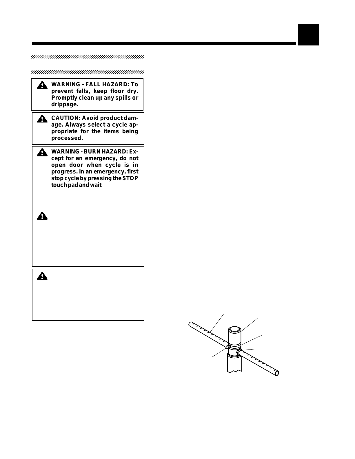
5. Observe (through window in door) operation of the spray
assemblies.Allrotaryspray assemblies shouldrotatefreely.If
they do not, press STOP, open the door, and clean out spray
armnozzleswithathinpieceofwire(seeFigure4-1).Closethe
door and press START.
6. Check all safety features.
a. Beingcarefulofhotwaterescaping,openfront(soiled)side
chamber door. Safety lock-out feature should shut all ser-
vice off. Close door and press START to resume cycle.
b. Open back (clean) side chamber door. Safety lock-out
feature should shut all service off. Close door and press
START to resume cycle.
7. Check pump rotation. Pump should rotate clockwise (while
facing it) as indicated by arrow on pump motor.
8. Check fan rotation. Arrow on fan indicates proper direction.
OPERATIONAL TESTS 4
First Operational Test
12345678901234567890123456789012123456789012345678901234567
1
234567890123456789012345678901212345678901234567890123456
7
12345678901234567890123456789012123456789012345678901234567
12345678901234567890123456789012123456789012345678901234567
1
234567890123456789012345678901212345678901234567890123456
7
12345678901234567890123456789012123456789012345678901234567
WARNING - FALL HAZARD: To
prevent falls, keep floor dry.
Promptly clean up any spills or
drippage.
CAUTION: Avoid product dam-
age. Always select a cycle ap-
propriate for the items being
processed.
WARNING-BURNHAZARD:Ex-
cept for an emergency, do not
open door when cycle is in
progress. In an emergency, first
stopcyclebypressingtheSTOP
touchpadandwaitforwaterflow
to stop. Wear protective gloves
andfaceshieldwheneverreach-
ing into the chamber.
WARNING - BURN HAZARD:
When checking automatic stop
feature, open chamber door
slowlyandweargloves andface
protection.Hotwater/steammay
be sprayed through door open-
ingifdoorisopenedwhilewasher
is operating.
CAUTION: Once three-phase
powerisconnected,checkpump
forcorrect rotation,indicatedby
arrow on pump motor. Incorrect
pumprotationmayresultinpump
damage and improper washing
action.
Figure 4-1. Rotary Spray ArmsFigure 4-1. Rotary Spray Arms
Figure 4-1. Rotary Spray ArmsFigure 4-1. Rotary Spray Arms
Figure 4-1. Rotary Spray Arms
Spray Arm
Nut
Manifold Connector
Sleeve
Bolt

4-2
122990-172 Operational Tests
Installation/Uncrating Instructions
9. When cycle is over, the CYCLE COMPLETE light comes on.
Open door and remove the accessory.
10. Clean chamber filters. Replace filters in chamber and close
chamber doors.
NOTE: Always use a non-foaming detergent for effective cleaning
and proper pump and water level control operation.
NOTE: Refer to Section 2 and follow detergent manufacturer's
recommendations to determine the temperature of the WASH
treatment.
NOTE: Follow detergent manufacturer's recommendations for the
amount of detergent used according to water hardness.
1. Open injection pump access door (lower right).
2. Slideinjectionpumpdraweroutfromunderwasher/disinfector.
3. Installone-gallondetergentandlubricantcontainers(see Fig-
ure 4-2).
4. Insert squeeze tube into each container.
5. Using the PRIME switch beside each injection pump, fill up
tubing between container and pump.
6. Select Instrument cycle by pressing INSTRUMENT button.
7. Press START button.
8. VerifydetergentisinjectedintochamberduringWashphaseas
soon as chamber begins to fill.
Check detergent concentration. Pump injection rate is
10 oz/min (284 ml/min). The detergent injection time is preset
at34seconds.Tomodifyconcentration,adjusttheappropriate
timer located in the injection pump drawer.
Figure 4-2. Detergent/Lubricant Container in place
Second Operational Test
12345678901234567890123456789012123456789012345678901234567
12345678901234567890123456789012123456789012345678901234567
12345678901234567890123456789012123456789012345678901234567
1
234567890123456789012345678901212345678901234567890123456
7
12345678901234567890123456789012123456789012345678901234567
CAUTION:Whenchoosingdeter-CAUTION:Whenchoosingdeter-
CAUTION:Whenchoosingdeter-CAUTION:Whenchoosingdeter-
CAUTION:Whenchoosingdeter-
gent, select one with a low chlo-gent, select one with a low chlo-
gent, select one with a low chlo-gent, select one with a low chlo-
gent, select one with a low chlo-
ride content. Detergents with aride content. Detergents with a
ride content. Detergents with aride content. Detergents with a
ride content. Detergents with a
high chloride content must nothigh chloride content must not
high chloride content must nothigh chloride content must not
high chloride content must not
be used, as chlorides will harmbe used, as chlorides will harm
be used, as chlorides will harmbe used, as chlorides will harm
be used, as chlorides will harm
and deteriorate stainless steel.and deteriorate stainless steel.
and deteriorate stainless steel.and deteriorate stainless steel.
and deteriorate stainless steel.
WARNING - CHEMICAL BURNWARNING - CHEMICAL BURN
WARNING - CHEMICAL BURNWARNING - CHEMICAL BURN
WARNING - CHEMICAL BURN
HAZARD:Washer/Disinfectorde-HAZARD:Washer/Disinfectorde-
HAZARD:Washer/Disinfectorde-HAZARD:Washer/Disinfectorde-
HAZARD:Washer/Disinfectorde-
tergents are caustic and cantergents are caustic and can
tergents are caustic and cantergents are caustic and can
tergents are caustic and can
causeadverseeffectstoexposedcauseadverseeffectstoexposed
causeadverseeffectstoexposedcauseadverseeffectstoexposed
causeadverseeffectstoexposed
tissues. Do not get in eyes, ontissues. Do not get in eyes, on
tissues. Do not get in eyes, ontissues. Do not get in eyes, on
tissues. Do not get in eyes, on
skin or attempt to ingest byskin or attempt to ingest by
skin or attempt to ingest byskin or attempt to ingest by
skin or attempt to ingest by
mouth. Read and follow the pre-mouth. Read and follow the pre-
mouth. Read and follow the pre-mouth. Read and follow the pre-
mouth. Read and follow the pre-
cautions and instructions on thecautions and instructions on the
cautions and instructions on thecautions and instructions on the
cautions and instructions on the
detergent label and in the MSDSdetergent label and in the MSDS
detergent label and in the MSDSdetergent label and in the MSDS
detergent label and in the MSDS
prior to handling the detergentprior to handling the detergent
prior to handling the detergentprior to handling the detergent
prior to handling the detergent
or refilling the detergent con-or refilling the detergent con-
or refilling the detergent con-or refilling the detergent con-
or refilling the detergent con-
tainer. Wear protective gloves,tainer. Wear protective gloves,
tainer. Wear protective gloves,tainer. Wear protective gloves,
tainer. Wear protective gloves,
face shield and clothing when-face shield and clothing when-
face shield and clothing when-face shield and clothing when-
face shield and clothing when-
ever handling the detergent.ever handling the detergent.
ever handling the detergent.ever handling the detergent.
ever handling the detergent.
Container
Timer
Pump

4-3
122990-172Operational Tests Installation/Uncrating Instructions
9. Verify lubricant is injected into chamber during Lubrication
phase as soon as Purified Water Rinse phase is complete.
Checklubricantconcentration.Pumpinjectionrateis10oz/min
(284 ml/min). The lubricant injection time is preset at 60 sec-
onds. To modify concentration, adjust the appropriate timer
located in the injection pump drawer.
10. When cycle is complete, slide injection pump drawer back in
place. Close access door.
11. Press the POWER button to turn off the unit. POWER light
goes off.
This unit is now ready for a thorough System Field Test,
Calibration and a first time Preventive Maintenance Checklist
Inspection by a qualified STERIS service representative. Con-
tactyourSterisSalesRepresentativeforavailabilityandinformation
on this service. Refer to Maintenance Manual (P-764327-734) for
further details on these procedures.

The best way to prevent costly downtime due to equipment malfunction is with
regularlyscheduledmaintenanceperformedbyqualifiedtechnicianstrainedinthe
latesttechnology. STERISoffers annualmaintenance agreementsto giveyour capital
equipmentplannedmaintenance that will helpcorrectlittleproblems before they
becomebigones.STERISEngineeringServicecombinestheprecisemaintenance
programand factory-trainedtechnicians to assureyou ofmaximum productivity.
Our STERIS service technicians thoroughly inspect, clean, adjust and provide all
necessarymaintenancetokeepyourequipmentperformingaccordingtofactoryspeci-
fications, all at an established economical rate that you can plan for.
Wehavemore than 5,000customerswhoare benefiting fromSTERISmaintenance
agreements.Why not jointhem? Obtain completedetails by calling1-800-333-8828, or
writing to:
Protect your STERIS equipment with
cost-effective extended service agreements
Table of contents
Other Steris Washer manuals

Steris
Steris RELIANCE 400 User manual

Steris
Steris ML 200 User manual

Steris
Steris Basil 4600 User manual

Steris
Steris BASIL 9500 User manual

Steris
Steris AMSCO 7000 Series User manual

Steris
Steris RELIANCE 400 User manual

Steris
Steris AMSCO 5000 Series User manual

Steris
Steris ML 222 User manual

Steris
Steris Reliance 1227 User manual

Steris
Steris RELIANCE 200 User manual


