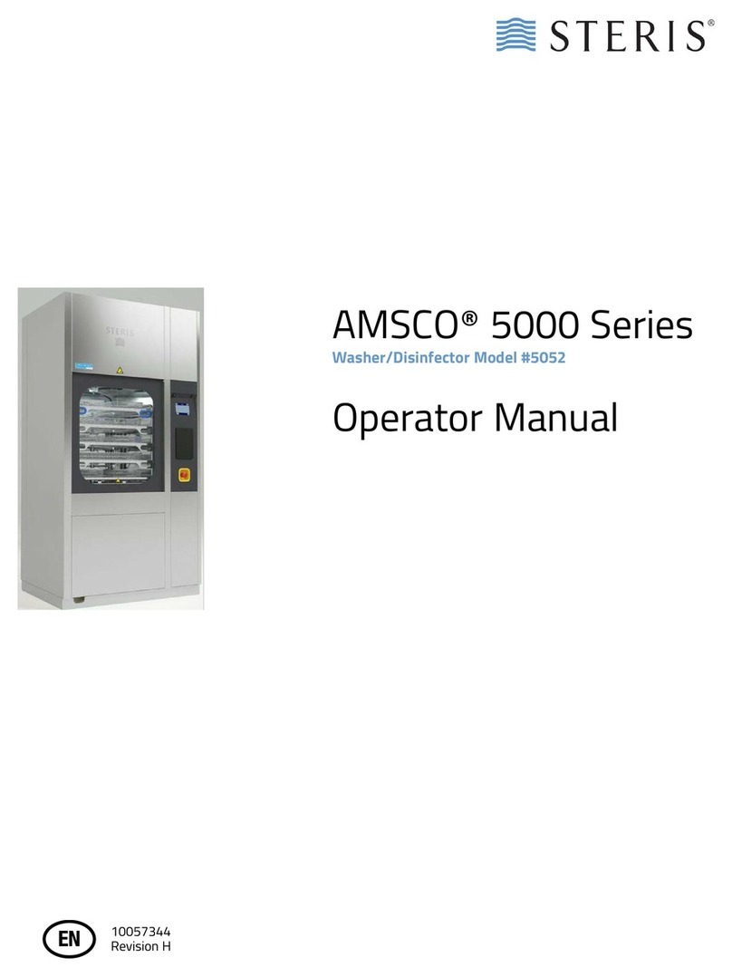
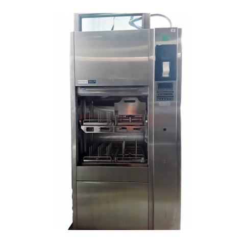
Steris RELIANCE 400 User manual

RELIANCE®400
LABORATORY GLASSWARE WASHER
SD574 (03/01/10)
Item ________________________
Location(s)___________________
____________________________
(Typical only - some details may vary.)
The Selections Checked Below Apply To This Equipment
MODEL
❑Steam-Heated Unit
VOLTAGE
❑120/208 Volt, 60 Hz, 3-Phase, 4-Wire
❑380/400/415 Volt, 50 Hz, 3-Phase, 3-Wire
❑480 Volt, 60 Hz, 3-Phase, 3-Wire
❑600 Volt, 60 Hz, 3-Phase, 3-Wire
❑Electric-Heated Unit
VOLTAGE
❑380/400/415 Volt, 50 Hz, 3-Phase, 3-Wire
❑480 Volt, 60 Hz, 3-Phase, 3-Wire
❑600 Volt, 60 Hz, 3-Phase, 3-Wire
POWER DOOR CONFIGURATION
❑Single Door
❑Double Door (Pass-Through)
OPTIONS
❑Non-Recirculated Heated Pure Water Rinse
❑Non-Vented Vapor Condenser
❑Drain Discharge Cool Down and Cold Water
Pre-Wash
❑Drying System
❑Universal Shelving System
ACCESSORIES*
❑Additional (Maximum Two) Chemical Pump(s)
❑Air Compressor
❑110-115 Volt
❑200-240 Volt
❑Barrier Wall Flange Assembly
* Refer to SD419 for material handling accessories
APPLICATION
The Reliance 400 Laboratory Glassware Washer is
designed for thorough cleaning of laboratory glassware,
plastic and metal goods used in research, production
support and quality control laboratories.
DESCRIPTION
The Reliance 400 Laboratory Glassware Washer is a
cabinet-type washer equipped with an Eagle 3000 Stage
3 control system. The washer is preprogrammed with three
adjustable cycles: light, medium and heavy. Seven
additional cycles are available for customized
programming to meet specific operating requirements.
Pre-programmed descaling and priming cycles are also
provided for routine maintenance.
Washer is built to seismic building code requirements and
is available as a single- or double-door unit, for installation
either as a freestanding unit or recessed through a barrier
wall(s).
Size (W x H x L)
Chamber load capacity:
• 26 x 25-1/2 x 26" (660 x 647 x 660 mm)
Overall dimensions:
• 42 x 80-3/4 x 32-1/2" (1067 x 2051 x 825 mm)
STANDARDS
The Reliance 400 Glassware Washer meets the applicable
requirements of the following standards, as certified by UL:
•Underwriters Laboratories (UL) Standard 61010-1.
•Canadian Standards Association (CSA):
CAN/CSA-C22.2 No. 61010-1.
•International Standard EN/IEC 61010-1.
•International Standard EN/IEC 61326.
•Governing Directive for the Affixing of the CE Mark:
Machinery Directive (98/37/EC).
•Conformity to other applicable directives: Electromagnetic
Compatibility Directive (89/336/EEC) amended by Directive 91/
263/EEC, Directive 92/31/EEC, and Directive 93/68/EEC; Low
Voltage Directive 2006/95/EC.
FEATURES
Vertical sliding power door(s)
is constructed of tinted, tempered
glass with stainless-steel trim, allowing the operator to view the
chamber with door(s) closed. While cycle is in progress, glass
remains cool to the touch. Power sliding door(s) operates
automatically by pneumatic cylinders when the appropriate touch
pad is pressed. The door is equipped with a safety switch to
automatically retract (open) the door if obstruction is detected in the
doorway. If power failure occurs, the door can be manually opened.

2
Manual access handle is on the top edge of the door, behind
the top service panel. If double power doors are ordered, a door
interlock feature is provided to prevent contamination. The door
interlock system allows only one door to be opened at a time,
and prevents either door from being opened when the cycle is
in progress, until STOP/RESET touch pad is pressed.
A 16-watt fluorescent light, mounted within an explosion/
vaporproof enclosure, illuminates the wash chamber.
Spray system
includes two manifold connectors positioned on
the bottom of the chamber, and one rotary spray arm suspended
from the top of the chamber. Manifold connectors automatically
connect to accessory headers at the start of each cycle.
Two removable stainless-steel debris screens, located in
the bottom of the wash chamber (sump), prevent large debris
from entering the piping system and pump.
Two adjustable peristaltic pumps automatically dispense a
selected amount of liquid chemicals (1/4 to 2.0 oz/U.S. gal
[2.0 to 16 mL/L]) into the chamber sump during desired
treatment. 50' (15 m) of tubing and electrical wiring, pick-up
tubes and low level sensors for remote location of chemical
containers are included.
Water saver feature allows the operator to retain water used
during the final rinse treatment for reuse during the first
treatment of the next cycle. Water can be retained only if no
chemicals were used during the final rinse treatment and if
optional drying was not selected. If retained water is too hot for
reuse in first treatment of the next cycle, or if optional cold water
pre-wash is selected, water will be automatically drained from
the sump.
Vapor removal fan (1/15 HP, 50 W) is provided to remove
vapor from the chamber throughout the cycle.
Control panel, with display window and touch pads, allows
easy initiation, programming and monitoring of all cycle
treatments. Display window features a 2-line x 20-character
easy-to-read vacuum fluorescent display.
Control system includes three preprogrammed cycles to
accommodate typical load and processing requirements.
Control can retain in memory up to ten processing cycles,
programmed and named according to Customer preferences.
Once a cycle is started, the programmed cycle values are
locked in and cannot be changed until cycle is complete.
Control system is equipped with a
Service Mode
for preventive
maintenance testing and to facilitate troubleshooting. A built-in
service diagnostic program is included to permit system
calibration and verification of component operations. Control
also includes
Cycle/Day Count Recall
system to remind
operator when a complete preventive maintenance check is
required.
ProConnect™ Response Center includes Remote
Monitoring, Priority Technical Support and Equipment
Performance Reports, as well as access to eservice.steris.com
to schedule and track service requests and purchase service
parts. Access to STERIS ProConnect Response Center is
provided free during the warranty period as part of the
equipment purchase. Available in North America only.
Integral thermal printer with automatic paper take-up
provides an easy-to-read record of all pertinent cycle data.
Printout includes cycle name, starting time and date of cycle,
completion time of each treatment and a list of any cycle
deviations that occurred. Any deviations in the cycle will set off
visible and audible alarms for acknowledgment by the
operator.
CYCLE DESCRIPTION
The Reliance 400 Washer features 10 programmable cycles.
Each cycle can be programmed to include up to 16 separate
treatments. Possible standard treatments include: up to four
pre-wash, up to four wash, up to four rinse and up to four pure
water rinse treatments. Once a cycle is selected, the washer
automatically processes the load through the programmed
treatments.
The washer is programmed with three factory-set processing
cycles: LIGHT, MEDIUM and HEAVY. All three factory-set
cycles can be modified by the operator to include the following
treatments:
•PRE-WASH: Load is sprayed with recirculated water at the
selected temperature (hot or optional cold) for a selected
amount of time (0-15 minutes). On completion of treatment,
water is sent to drain.
•WASH: Load is sprayed with recirculated solution at the
selected temperature (hot or heated, in the sump, to 190°F
[88°C]) for the selected amount of time (0-15 minutes). A
controlled amount of chemical detergent is automatically
added to sump at the beginning of treatment. If heated water
is selected, treatment will not start until selected temperature
is reached. On completion of treatment, solution is sent to
drain.
•RINSE: Load is sprayed with recirculated water at the
selected temperature (optional cold, hot or heated, in the
sump, to 190°F [88°C]) for the selected amount of time (0-
15 minutes). If heated water is selected, treatment will not
start until selected temperature is reached. On the
completion of treatment, water is sent to drain.
•PURE WATER RINSE: Load is either sprayed with
recirculated pure water at the selected temperature
(ambient or heated, in the sump, to 190°F [88°C]) for a
selected amount of time (0-15 minutes), or sprayed with non-
recirculated pure water (supplied from optional storage
tank) for 10 seconds. If heated water is selected, treatment
will not start until the selected temperature is reached. On
completion of treatment, water is either sent to drain or
retained for use in the first treatment of the next cycle.

3
SAFETY FEATURES
Safety door switch prevents a cycle from starting if the door
is not fully closed and stops the washer operation if door is
opened during a cycle.
Door cable safety latch prevents the door from falling in case
of accidental cable breakage.
Main power ON/OFF switch on electrical supply box can be
used to shut off power to the control system.
OPTIONAL FEATURES
Non-recirculated heated pure water rinse treatment can be
programmed to spray the load with heated pure water.
Pure water is stored in an integral electropolished stainless-
steel tank equipped with an automatic fill, level control and
overflow sensors. Pure water rinse treatment(s) can be
programmed to use recirculated or non-recirculated pure
water.
A steam or electric heating coil is located in the bottom of the
storage tank to heat and maintain pure water temperature up
to 190°F (88°C).
Non-vented vapor condensor for exhausting vapor through
a cold-water condensor to the room, eliminating the need for
venting the unit.
Drain discharge cool down and cold water pre-wash
treatment can be programmed to spray load with recirculated
cold tap water. At the end of each treatment, drain discharge
feature ensures water drained to the building drain system does
not exceed 140°F (60°C). If water temperature in the chamber
sump is greater than 140°F (60°C), cold water is automatically
added to reduce temperature of water being discharged to
building drain.
Drying system treatment can be programmed to occur after
the final rinse treatment of a cycle. During Drying treatment,
chamber air is heated to the selected temperature (up to 240°F
[116°C]) and recirculated through the chamber and accessory
headers, while a portion is exhausted to vent. System includes
a 1.5 HP (1.1 kW) blower and electric heaters.
Universal shelving system for two-level cleaning capability.
The removable loading shelf is made of two sections: one
section can easily be removed so only half of the wash chamber
has a two-level configuration, providing ultimate flexibility for
processing small, medium and large glassware items
simultaneously.
CONSTRUCTION
Wash chamber is constructed of #304 stainless steel (No. 4
finish), argon-welded and polished. Washer frame, cabinet,
door and fasteners are of #304 stainless steel (No. 4 finish).
Optional pure water tank is made of #316 stainless steel.
All treatments are under pressure of a stainless-steel pump
with dual-speed (7.5/1.9 HP [5.6/1.5 kW]) motor. (High speed
is for use only with the optional Multiple Level Loading System.)
Pump impeller, shaft and casing are fitted with a mechanical
seal. The pump motor is equipped with drip-proof frame,
magnetic starter, overload protection and sealed bearings
(requiring no periodic lubrication).
All components of the spray system, including screens, rotary
spray arm and recirculation piping, are constructed of #304
stainless steel.
A valve is installed in the sump to facilitate sampling of wash
and rinse water.
An internal battery backs up all cycle memory for up to 10 years.
If a power disruption occurs during a cycle, the battery permits
completion of the cycle once power is restored.
Resistive Temperature Devices (RTDs) sense the temperature
inside the wash chamber and pure water tank. Signals,
converted into electrical impulses, provide accurate control
inputs/readouts throughout all cycles.
Washer is interpiped and interwired, requiring only one
connection for each service and utility hook-up.
ACCESSORIES*
Additional chemical pump(s) can be installed on the washer
(up to two additional peristaltic pumps) for injections of different
chemicals during desired treatments.
Air compressor is complete with automatic tank drain and
pressure switch. Wiring at installation is not provided by
STERIS.
Barrier wall flange kit includes six stainless-steel flanges to
seal the opening between the recessed washer and wall.
* Refer to SD419 for information on material handling accessories, including
accessory headers and transfer carts.
PREVENTIVE MAINTENANCE
A global network of skilled service specialists can provide
periodic inspections and adjustments to help ensure low-cost
peak performance. STERIS representatives can provide
information regarding annual maintenance programs.

4
* At 75°F (24°C), 40% RH ambient.
** Calculated as described in ISO 3746 standard.
*** Based on medium cycle with default values.
NOTES
1. Pipe sizes shown indicate terminal outlets only. Building
service lines (not provided by STERIS) must supply the
specified pressures and flow rates.
2. For all ventilation ducting from washer, STERIS
recommends installation of dedicated, corrosion-proof,
watertight duct to exterior of building, sloped towards
washer. A 3.0" (76 mm) ID flexible duct is recommended.
3. Customer must ensure washer stands on a non-combustible
floor.
ENGINEERING DATA
Max.
Shipping
Weight
lbs
(kg)
Max.
Shipping
Dimensions
In
(mm)
Max.
Operating
Weight
lbs
(kg)
Heat
Loss
A-weighted
Equivalent
Surface
Sound
Pressure
Level**
dB A
Max. Water
Consumption
per Cycle*** Max. Steam
Consumption
per Cycle***
lbs
(kg)
Vented
BTU/hr
(kJ/hr)
Non-vented
BTU/hr
(kJ/hr)
Hot Water
gal
(L)
Pure
Water
gal
(L)
1075
(488)
42x91x50
(1067x2311x1270)
1200
(544)
1580
(1667)
7200
(7596)
67.6 50.4
(190.8)
12.6
(47.7)
8.3
(3.76)
The base language of this document is
ENGLISH. Any translations must be made
from the base language document.

5
UTILITY REQUIREMENTS
IMPORTANT: Refer to equipment drawing 122-992-953 for
installation details.
Hot Water
1/2" NPT; 15 to 50 dynamic psig (103 to 345 kPa), maximum
90 psig (621 kPa) static; 110°F (43°C) minimum. Minimum
flow rate: 3.9 gpm (14.7 L/min); maximum 7.5 U.S. gpm
(28.5 L/min).
Cold Water (if option applies)
1/2" NPT; 30 to 50 dynamic psig (206 to 345 kPa), maximum
90 psig (621 kPa) static; 60°F (16°C) maximum. Minimum
flow rate: 5.6 gpm (21.4 L/min). Maximum: 7.5 U.S. gpm
(28.5 L/min).
Steam
(Steam-Heated Unit only)
3/4" NPT; 30-80 psig (206-550 kPa) dynamic; 185-400 lbs/
hr (84-181 kg/hr). Peak flow rate: 210-470 lbs/hr (95-213 kg/
hr). Maximum 90 psig (620 kPa) static.
Condensate Return
(Steam-Heated Unit only)
1/2" NPT. Peak flow rate: 1.0 U.S. gpm (4.0 L/min).
Pure Water
1/2" NPT; 5 to 50 dynamic psig (35 to 345 kPa), maximum
90 psig (621 kPa) static. Minimum flow rate: 4 U.S. gpm (15 L/
min) maximum. 7.5 U.S. gpm (28.5 L/min). Minimum specific
resistivity of 0.1 megohm/cm recommended.
Air
1/8" NPT; 65 dynamic to 125 static psig (448-860 kPa). Flow
rate: 1 scfm (0.03m3/min). Maximum particle size:
40 microns. Maximum particle density: 10 mg/m3. Maximum
dew point for water content: 45°F (7°C). Maximum oil
concentration for oil content: 25 mg/m3, as per ISO-8573-1,
Class 5.
Vent
3" (76 mm) O.D.; 75 scfm (2.123 m3/sec) (Not required if non-
vented condenser option is selected.)
Drain
2" NPT; a 4" (102 mm) O.D. floor funnel or open drain, and
4" (102 mm) O.D. floor sink is recommended. Gravity drain
maximum flow rate: 15 U.S. gpm (57 L/min). Pump drain
maximum flow rate: 90 U.S. gpm (342 L/min).
Electricity
3/4" (19 mm) conduit size; 1" (25.4 mm) if over 24 Amps.
Electricity (Steam-Heated Unit) With Drying System
120/208 V, 60 Hz, 3-Phase, 4-Wire, 27 Amps; or 480 V, 60 Hz,
3-Phase, 3-Wire, 12.5 Amps; or 380/400/415 V, 50 Hz, 3-
Phase, 3-Wire, 13 Amps; or 600 V, 60 Hz, 3-Phase, 3-Wire,
12 Amps.
Electricity (Steam-Heated Unit) Without Drying System
120/208 V, 60 Hz, 3-Phase, 4-Wire, 14.5 Amps; or 480 V,
60 Hz, 3-Phase, 3-wire, 7 Amps; or 380/400/415 V, 50 Hz, 3-
Phase, 3-Wire, 7 Amps; or 600 V, 60 Hz, 3-Phase, 3-Wire,
9Amps.
Electricity (Electric-Heated Unit) With or Without Drying
System
480 V, 60 Hz, 3-Phase, 3-Wire, 26.5 Amps; or
380/400/415 V, 50 Hz, 3-Phase, 3-Wire, 31 Amps; or 600 V,
60 Hz, 3-Phase, 3-Wire, 24 Amps.
Telecommunications (required for Remote Service
Response Center, Available in North America only)
ProConnect™Response Center requires an active wired or
wireless TCP/IP network; 10/100Base T Ethernet connection
at each piece of connected equipment, Internet access and
an IP address on the owner’s building network. Ethernet
cables/wireless hardware to connect each piece of
equipment to the facility network will be provided by the
owner. Owner will provide a dedicated PC for each unit with
Windows XP®1operating system, a 2.8GHz processor,
512MB of RAM and 5 GB of available hard drive space to
run the service agent along with a local login at the PC with
vendor supplied username and password.
CUSTOMER IS RESPONSIBLE FOR COMPLIANCE WITH
APPLICABLE LOCAL AND NATIONAL CODES AND
REGULATIONS.
NOTES
1. On 380/400/415 V units, NPT fittings are replaced by BSPT.
2. Maximum hardness for hot and cold water is 120 ppm
(CaCO3).
1. Windows XP is a registered trademark of Microsoft Corporation.

6
Reference the following equipment drawings for installation details.
Equip. Dwg. No. Equipment Drawing Title
122-992-953EN Reliance 400 Laboratory Glassware Washer Domestic - International - English
Dimensions are inches (mm)
Dimensions are typical -
drawing is not to scale.
NotForInstallation

7
NOTES
Recommended Air Compressor
1. Enclosure must be well ventilated with a good air path to
and from the ends of the compressor.
2. Inlet air temperature should be between 32°F (0°C) and
100°F (38°C). Locate air inlet outside of enclosed service
areas. Inlet air pipe size is 1/4" (6 mm). Increase pipe
diameter one size for every 10' (3048 mm) inlet filter is placed
away from sink.
3. Use 3/8" (10 mm) or larger pipe between compressor and
glassware washer when compressor is remotely located.
4. Electrical cord is not included.
UTILITY REQUIREMENTS
Recommended Air Compressor
Electrical - Compressor Motor
110-115 Volt, 50/60 Hz, 1-Phase, 4.4 Amps.
or
200-240 Volt, 50/60 Hz, 1-Phase, 1.4 Amps.
ENGINEERING DATA - RECOMMENDED AIR COMPRESSOR WITH AUTOMATIC TANK DRAIN
HP
(kW)
CFM
Open
Flow
(cmm)
Weight
lbs
(kg)
Comp.
Stage
s
Cyl.
TANK MOTOR
Noise
Level
dB
Lubrication Size
In (mm)
Capacity
US gal (L)
Max. Press
psig (bar)
Operating
Speed
Hz (rpm)
1/3
(0.25
2.0
(.06)
42
(19)
1 1 Oiless See Below 2.0
(7.6)
100
(6.9)
50 (1400)
60 (1675)
69
Reference the following equipment drawings for installation details.
Equip. Dwg. No. Equipment Drawing Title
920-005-138EN Air Compressor With Automatic Tank Drain Domestic - International - English
Approx.
8-1/4"
(210 mm)
Approx.
18"
(457 mm)
Approx.
4"
(100 mm)
Approx.
5-1/2"
(140 mm)
Approx.
18"
(457 mm)
Approx.
10"
(255 mm)
Approx.
1"
(254 mm)
Dimensions are inches (mm)
Dimensions are t
y
pical
–
drawin
g
is not to scale.
App
rox.
8
-
1/4"
(
210 mm
)
A
pprox.
18"
(45
7 m
m)
App
p
App
pp
App
App
p
App
pp
pp
pp
pp
p
pp
App
pp
App
pp
p
App
p
App
pp
p
rox
.
4"
(10
0
m
m)
App
rox.
5-1
/2"
App
rox
.
18"
(4
57 mm
)
A
pprox
.
10"
(
255 mm
)
App
rox
.
1
"
(25
4
m
m)
Di
mens
io
o
o
o
o
o
o
o
o
o
o
o
o
o
o
o
o
o
o
o
o
o
ns
ns
ns
s
ns
ns
ns
ns
ns
ns
ns
n
ns
s
ns
ns
ns
n
n
n
n
a
a
a
a
a
a
a
a
a
a
a
a
a
a
a
a
a
a
re
r
dr
d
d
d
d
d
d
d
d
d
d
d
d
d
d
d
d
aw
aw
w
aw
aw
aw
aw
w
w
w
w
aw
w
aw
aw
w
w
w
aw
a
a
a
w
w
w
a
in
in
in
i
in
in
n
n
in
in
in
i
in
n
n
n
g
g
g
g
g
g
g
g
g
g
g
g
g
g
g
g
g
g
g
g
g
i
i
i
i
i
i
i
i
i
i
i
i
i
i
i
i
ss
no
o
o
o
o
o
o
o
o
o
o
o
o
o
o
o
o
t
t
t
t
t
t
t
t
t
t
t
t
t
t
t
t
t
t

For Further Information, contact:
STERIS Corporation
5960 Heisley Road
Mentor, OH 44060-1834 • USA
440-354-2600 • 800-548-4873
www.steris.com
This document is intended for the exclusive use of STERIS Customers, including
architects or designers. Reproduction in whole or in part by any party other than
a Customer is prohibited.
SD574 ©2010, STERIS Corporation. All rights reserved. (03/01/10)
Other manuals for RELIANCE 400
1
Table of contents
Other Steris Washer manuals

Steris
Steris AMSCO RELIANCE 430 User manual

Steris
Steris RELIANCE 400 User manual

Steris
Steris ML 200 User manual

Steris
Steris BASIL 9500 User manual

Steris
Steris Reliance 1227 User manual

Steris
Steris AMSCO 7000 Series User manual

Steris
Steris ML 222 User manual

Steris
Steris AMSCO 5000 Series User manual

Steris
Steris RELIANCE 200 User manual

Steris
Steris Basil 4600 User manual