Steris BASIL 9500 User manual

OPERATOR MANUAL
BASIL® 9500
Cage and Rack Washer
(10/18/01) P-122998-050
Rev. 3

LIMITATIONS OF LIABILITY AND INDEMNITY
IN NO CASE, WHETHER AS A RESULT OF A BREACH OF CONTRACT, BREACH OF WARRANTY
OR TORT (INCLUDING STERIS'S OR CUSTOMER'S WILLFUL ACTS OR NEGLIGENCE OR STRICT
LIABILITY) SHALL STERIS OR CUSTOMER BE LIABLE TO THE OTHER FOR ANY CONSEQUEN-
TIAL OR INCIDENTAL DAMAGES INCURRED BY THE OTHER, INCLUDING, BUT NOT LIMITED TO,
LOSS OF REVENUE, PROFITS OR GOODWILL. HOWEVER, NOTHING CONTAINED IN THIS
AGREEMENT IS INTENDED TO RELIEVE EITHER STERIS OR CUSTOMER FROM CLAIMS,
LIABILITY, DAMAGES OR EXPENSES RESULTING FROM BODILY INJURY, INCLUDING DEATH,
OR FROM PROPERTY DAMAGE INCURRED DUE TO THE WILLFUL ACTS, THE NEGLIGENCE OF
OR THE STRICT LIABILITY OF THAT PARTY.
STERIS AGREES TO DEFEND, INDEMNIFY AND HOLD CUSTOMER HARMLESS FROM ANY AND
ALL CLAIMS, LIABILITY, DAMAGES OR EXPENSES DUE TO PERSONAL INJURIES, INCLUDING
DEATH, TO EMPLOYEES OF STERIS AND CUSTOMER AND TO THIRD PARTIES AND FOR
PROPERTYDAMAGETOTHEEXTENTOFTHEWILLFULACTSOFTHENEGLIGENCEOFSTERIS
OR THE STRICT LIABILITY OF STERIS CAUSED BY THE ACTS OR OMISSIONS OF STERIS.
CUSTOMER AGREES TO DEFEND, INDEMNIFY AND HOLD STERIS HARMLESS FROM ANY AND
ALL CLAIMS, LIABILITY, DAMAGES OR EXPENSES DUE TO PERSONAL INJURIES, INCLUDING
DEATH, TO EMPLOYEES OF CUSTOMER AND STERIS AND TO THIRD PARTIES AND FROM
PROPERTY DAMAGE TO THE EXTENT OF THE WILLFUL ACTS OR THE NEGLIGENCE OF
CUSTOMER OR THE STRICT LIABILITY OF CUSTOMER CAUSED BY THE ACTS OR OMISSIONS
OF CUSTOMER.
WARNING - COPYING PROHIBITED
This manual is protected by Federal Copyright Law, which
provides for damages of up to $20,000, as well as
criminal fines and imprisonment, for unauthorized copying.

i
Introduction OperatorManual 122998-050
This manual contains important information on the proper use of this
washer. Refer to
Routine Maintenance, Section 6
for instructions in
routine care of this equipment. All personnel and department heads
are urged to carefully review and become familiar with the warnings,
cautionsandinstructionscontainedherein.Theseinstructionsshould
beretainedinaconvenientlyaccessibleareaforquickreference.This
washer is specifically designed only for the uses outlined in this
manual, otherwise, safety hazards may occur.
IMPORTANT
:
Alisting of thesafetyprecautionsto be observedwhen
operating this washer can be found in section 1. Do not operate the
washer until you have become familiar with this information.
The Basil®9500 Cage and Rack Washer is intended for use in the
sanitation of soiled, reusable animal care devices such as cages,
racks,debrispans,feederbottlesandothermiscellaneousitemsby
providing thorough cleaning, and optional drying.
Thiswasherisspecificallydesignedtoonlyprocessgoodsasoutlined
in this manual. If there is any doubt about a specific material or
product, contact the manufacturer of the product for recommended
washing technique.
STERISdoesnotintend,recommendnorrepresentinanywaythatthis
Basil 9500 Cage and Rack Washer be used for the sterilization of any
animal care or other device which has been contaminated with
pathogenic microorganisms.
Any alteration of the washer not authorized or performed by STERIS
Engineering Service which could affect its operation will void the
warranty, could adversely affect washing efficacy, could violate
national, State, and local regulations, and could jeopardize your
insurance coverage.
A thorough preventive maintenance program is essential to safe and
proper equipment operation. You are encouraged to contact your
STERIS representative concerning extended service maintenance
agreements to give your washer planned maintenance, assuring
equipment performance according to factory specifications.
A global network of skilled service specialists can provide periodic
inspections and adjustments to assure low-cost peak performance.
STERISrepresentativescanprovideinformationregardingtheAnnual
Maintenance Agreements.
STERIScarriesacompletelineofaccessoriesforuseinthisequipment.
A STERIS representative will gladly review these with you.
© 2001 - STERIS Corporation All rights reserved. Printed in Canada
12345678901234567890123456789012123456789012345678901234567
1
234567890123456789012345678901212345678901234567890123456
7
12345678901234567890123456789012123456789012345678901234567
12345678901234567890123456789012123456789012345678901234567
1
234567890123456789012345678901212345678901234567890123456
7
12345678901234567890123456789012123456789012345678901234567
Service Information
A WORD FROM STERIS CORPORATION
Indications For Use
12345678901234567890123456789012123456789012345678901234567
12345678901234567890123456789012123456789012345678901234567
12345678901234567890123456789012123456789012345678901234567
1
234567890123456789012345678901212345678901234567890123456
7
12345678901234567890123456789012123456789012345678901234567
Advisory
12345678901234567890123456789012123456789012345678901234567
12345678901234567890123456789012123456789012345678901234567
12345678901234567890123456789012123456789012345678901234567
1
234567890123456789012345678901212345678901234567890123456
7
12345678901234567890123456789012123456789012345678901234567

ii
122998-050 OperatorManual Introduction
Sales: Direct Technical Assistance:
STERIS Corporation STERIS Engineering Services
5960, Heisley Road 2424 West, 23rd Street
Mentor, Ohio 44060 Erie, PA 16506
Tel.: 440 354 2600 Tel.: 814 452 3100
Fax: 440 639 8199 Fax: 814 870 8400
ManufacturingPlant: Authorized EU Representative:
STERIS Canada Corporation STERIS Limited
415, rue des Alleghanys STERIS House
Beauport (Québec) Jays Close
Canada G1C 4N4 Viables
Tel.: 418 664 1549 Basingstoke
Fax.: 418 664 0188 Hampshire
RG22 4AX
Tel.: 44 1256 840400
Fax: 44 1256 866502
STERIS HAS OFFICES WORLDWIDE
Benelux 32 2 523 24 88
Canada 800 661 3937
France 33 1 4488 2688
Germany 49 2233 6999 0
Hong Kong 852 2 563 3623
Italy 39 02 66 80 53 10
Japan 81 78 321 2271
Korea 82 2 554 1661
Latin America 305 442 82 02
Nordic 358 9 25851
Singapore 65 841 7677
Spain 3491 658 5920
Sweden 46 152 228 30
United Kingdom 44 1256 840400
Visit our web site at: www.steris.com

iii
Introduction OperatorManual 122998-050
TABLE OF CONTENTS
SECTION TITLE PAGE
1 LISTING OF WARNINGS, CAUTIONS
AND SYMBOLS ...................................................... 1-1
Symbols ................................................................................. 1-4
2 INSTALLATION VERIFICATION ............................. 2-1
Installation Checklist................................................... 2-1
Technical Specifications............................................. 2-2
Certification ................................................................ 2-3
Chemical Additives Specifications.............................. 2-4
3 COMPONENT IDENTIFICATION ............................. 3-1
POWER-OFF/STANDBY Switch................................ 3-2
Main Control Panel..................................................... 3-2
Display Screen ............................................... 3-2
Touch Pads .................................................... 3-3
Printer ........................................................................ 3-4
Printer Function Switch.................................. 3-4
Typical Printouts ............................................ 3-5
Remote Control Panel (Double Door Units)................ 3-8
Emergency Safety Features....................................... 3-9
Photoelectric Sensors ................................... 3-9
Emergency Exit Safety Doors ....................... 3-9
Emergency Stop Guard Rails........................ 3-9
Emergency Stop Pushbutton(s) .................... 3-9
Interior Light ................................................ 3-10
Safety Delay................................................ 3-10
4 OPERATING INSTRUCTIONS................................. 4-1
Before Operating Washer........................................... 4-1
Priming Procedure ..................................................... 4-2
Doors ......................................................................... 4-3
Door Operation ............................................. 4-3
Double Door Units with Interlock Feature...... 4-4
Opening Doors During a Power Failure ........ 4-4
Accessories................................................................ 4-5
How to Load Accessories Into Wash
Chamber ...................................................... 4-5
How to Load Central Spray Header
Manifold(option) .......................................... 4-7
How to Load Bottle Washing Cart (option) ... 4-7

iv
122998-050 OperatorManual Introduction
Typical Cycle Operation............................... 4-9
To Begin Cycle Operation ............................ 4-9
Drain Cycle .............................................................. 4-12
Pause Cycle operation ............................................. 4-14
Abort Cycle operation............................................... 4-15
Acknowledge Alarm Condition.................................. 4-15
Shutdown ................................................................. 4-16
Manual Shutdown ..................................... 4-16
Automatic Shutdown ................................. 4-17
5 CYCLE AND CONTROL VALUE
PROGRAMMING ..................................................... 5-1
Cycle Description Chart..................................................... 5-2
Change Values Mode ........................................................ 5-3
Sequence of Display Screens ............................. 5-3
How to Modify a Cycle......................................... 5-3
Review Cycle Values ...................................................... 5-11
6 ROUTINE MAINTENANCE...................................... 6-1
Preventive Maintenance Schedule ................................... 6-1
Cleaning Procedures ........................................................ 6-4
Daily Cleaning ..................................................... 6-4
Weekly Cleaning ................................................. 6-6
Horizontal Spray Headers and Spray Jets.. ........ 6-7
Central Spray Header Manifold (Option) ............. 6-7
Rotary Spray Arms on Bottle Washing Cart
(Option)............................................................... 6-7
Strainers ............................................................. 6-7
Vertical Self Cleaning Filter ................................. 6-8
Descaler Cycle ................................................................. 6-8
Manual Descaler Cycle ....................................... 6-8
Automatic Descaler Cycle ................................. 6-12
Chemical Container Replacement .................................. 6-15
Injection Pumps Lubrication and Replacement ............... 6-16
Printer Paper Roll Replacement ..................................... 6-17
Thermal Paper Storage .................................................. 6-19
7 TROUBLESHOOTING ............................................. 7-1
TABLE OF CONTENTS (CONT'D)
SECTION TITLE PAGE

1-1
Listing of Warnings, Cautions and Symbols OperatorManual 122998-050
LISTING OF WARNINGS, CAUTIONS
AND SYMBOLS
The following is a listing of the safety warnings and cautions which must be observed when operating or
servicing this unit. WARNING indicates the potential for danger to personnel and CAUTION indicates the
potential for damage to equipment. These precautions are repeated in whole or in part, where applicable,
throughout the manual. Carefully read them before proceeding to use or service the unit.
WARNING – BURN HAZARD:
After pressing STOP/RESET touch pad, wait until water flow stops before opening doors. Hot water/
steam may be sprayed through door opening if doors are opened too soon.
Except for emergency, do not open door when cycle is in progress. In an emergency, first stop cycle
by pressing the EMERGENCY STOP PUSHBUTTON and wait for water flow to stop. Wear appropriate
personal protective equipment (PPE) whenever reaching into or entering wash chamber.
Except for emergency, do not open door when cycle is in progress. In an emergency, first stop cycle
by pressing the STOP/RESET touch pad and wait for water flow to stop. Wear appropriate personal
protective equipment (PPE) whenever reaching into or entering wash chamber.
Inner surfaces of washer are very hot after cycle completion. Operator should wear appropriate
personal protective equipment (PPE) and avoid all contact with inner walls when entering chamber
to unload washer.
WARNING – FALL HAZARD:
To prevent falls, keep floor dry. Promptly clean up any spills or drippage.
WARNING – PERSONAL INJURY AND/OR EQUIPMENT DAMAGE HAZARD:
Regularly scheduled preventive maintenance, in addition to the faithful performance of the minor
maintenance described within this manual, is required for safe and reliable operation of this
equipment. Contact STERIS Engineering Service to schedule preventive maintenance.
Only fully qualified service personnel should make repairs and adjustments to this equipment.
Maintenance done by inexperienced, unqualified personnel or installation of unauthorized parts
couldcausepersonalinjury,invalidatethewarranty,orresultincostlydamage.ContactyourSTERIS
sales or service representative regarding service options.
To open doors from inside wash chamber, press Emergency Safety Guard Rails. Washer operation
will automatically stop. Then, push firmly between door panels using shoulder and upper arm,
applying upper body force. Do not push between the two doors, but between the door panels.
To test or demonstrate Emergency Exit Safety Doors, first press Emergency Stop pushbutton
(locatedundercontrol) or EmergencySafety Guard Rails(insidewash chamber) toturnpower OFF.
If power is still on while adjusting or servicing doors, the photoelectric sensor will detect the
movement of the door panels and doors will open automatically.
Before servicing or cleaning exterior of unit, always press EMERGENCY STOP pushbutton to
de-energize unit.
Always wear appropriate personal protective equipment (PPE) when cleaning or removing debris
from bottom of the wash chamber and over the suction plate.
1
(See next page for additional Warnings and Cautions)

1-2
122998-050 OperatorManual Listing of Warnings, Cautions and Symbols
WARNING – PERSONAL INJURY HAZARD:
When doors are closing, a pinch point is created at the hinges. Keep fingers away from door hinges
in order to prevent pinching.
Never perform cleaning of wash chamber until full cycle has been completed. If cycle has not been
completed, contaminated debris or water may remain in the bottom of the wash chamber
Keep hands/fingers away from closing doors in order to prevent crushing between the two doors.
Ifdoorsarestillslightlyopen(lessthan2inches[5cm])whenpowerisrestoredafterapowerfailure,
controlwillapplypressuretocompleteclosing.Lockbuildingelectricalsupplydisconnectswitchin
OFF position and close unit air supply when opening doors after a power failure.
WARNING – ELECTRICAL SHOCK AND/OR BURN HAZARD:
Disconnectallutilitiestowasherbeforeservicing.Donotservicewasherunlessallutilitieshavebeen
properly locked out. Always follow local occupational health and safety regulations, as well as
electric and plumbing codes.
WARNING – CHEMICAL BURN AND/OR EYE INJURY HAZARD:
Wear appropriate personal protective equipment (PPE) when using a descaling product. Avoid
contactwitheyesorskin.Ifspilledorsplashed,flushwithwaterfor15minutes.Ifswallowed,DONOT
induce vomiting. Administer an alkali with plenty of water. Seek medical attention immediately.
Always use non-foaming chemical for effective cleaning and proper pump and water level control
operation. Follow manufacturer's recommendations for amount of chemical to be used.
Washerchemicals arecausticandcancauseadverseeffects toexposed tissues.Do notgetineyes,
on skin or attempt to ingest by mouth.
• Read and follow the precautions and instructions on the chemical label and in the Material Safety
Data Sheet (MSDS) prior to handling chemicals, refilling chemical containers or servicing the
chemical injection pumps and lines.
• Wear appropriate personal protective equipment (PPE) whenever handling chemicals or servicing
chemical injection pumps and lines.
CAUTION - POSSIBLE EQUIPMENT DAMAGE HAZARD:
Always use a silicone lubricant to lubricate squeeze tubes. Petroleum-based lubricants, such as
Vaseline®or grease, will cause squeeze tubes to melt.
When choosing a chemical, select one with a low chloride content. Chloride is harmful to stainless
steel and will deteriorate washer.
AlwayspositionCentralHeaderManifoldoverthemanifoldedcouplingsystembeforeoperatingunit.
Ifmanifold isnotpositioned correctly,damage mayresultand unitwill beunableto effectivelywash
load.
AlwayspositionBottleWashingCartovercentralwaterinletconnectorbeforeoperatingunit.IfBottle
Washing Cart is not positioned correctly, damage may result and unit will be unable to effectively
wash load.
(See next page for additional Warnings and Cautions)

1-3
Listing of Warnings, Cautions and Symbols OperatorManual 122998-050
Avoid product damage. Always select a cycle appropriate for the items being processed.
Use non-abrasive cleaners when cleaning unit. Follow directions on containers and rub in a back-
and-forthmotion, insamedirectionassurface grain. Abrasivecleaners willdamagestainlesssteel.
Cleanersrubbed inacircular motionorapplied witha wirebrushor steelwoolon doorand chamber
assemblies can be harmful to stainless steel. Do not use these cleaners on painted surfaces.
Keep away from doors to prevent load detection sensor from stopping doors from closing.
Alwaysleaveplentyofspacebetweenloadanddoors.Leaningloadagainstdoorswilldamagedoors
and also prevent them from opening or closing.
Remove all cellulose type bedding from cages and pans before processing. Cellulose bedding may
clog filters and piping.
1-4
122998-050 OperatorManual Listing of Warnings, Cautions and Symbols
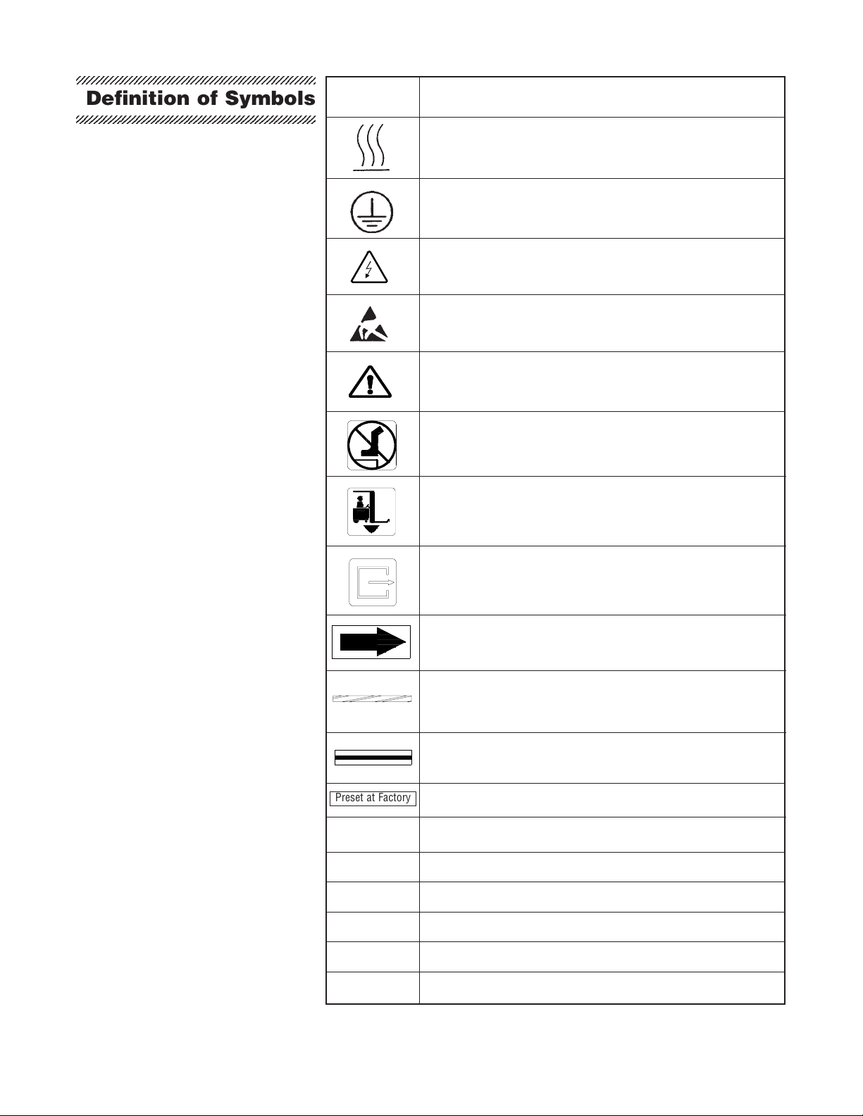
Symbol Definition
Transfer of Heat, Hot Surface
Protective Earth (Ground)
Warning! Risk of Electrical Shock
Electrostatic Sensitive Device
Attention, Consult Manual for Further Instructions
Warning! Do not step here.
Fork Lift: Place forks of the fork lift here.
Safety Exit: Push here in case of an emergency.
Rotation: Direction of the rotating device.
Emergency Stop Guard Rails: Push to stop the washer
and de-energize control.
Load delimitation: Do not place load over these marks.
Factory adjustment: Do not adjust.
AAmperage Rating of the unit
VVoltage Rating of the unit
~Alternating Current
kW Power Rating of the unit
Hz Frequency of the unit
fPhase of the unit
123456789012345678901234567890121234567890123456789
1
2345678901234567890123456789012123456789012345678
9
123456789012345678901234567890121234567890123456789
123456789012345678901234567890121234567890123456789
1
2345678901234567890123456789012123456789012345678
9
123456789012345678901234567890121234567890123456789
Definition of Symbols
Preset at Factory

2-1
InstallationVerification OperatorManual 122998-050
AnEquipmentDrawing,showingallutilityandspacerequirements,
wassenttoyouaftertheorderforthisequipmentwasreceived.The
clearancespace,specifiedonEquipmentDrawing,isnecessaryfor
proper installation, operation and maintenance. Uncrating and In-
stallationInstructionswereprovidedwiththewasher.Ifanyofthese
documents are missing or misplaced, contact STERIS giving the
serial, equipment and model numbers of the unit. Replacement
copies will be sent to you promptly.
After installing the washer according to the Uncrating and Installa-
tion Instructions, complete the following checklist to assure com-
plete and correct installation. Or contact your STERIS representa-
tive to schedule a technician to test your installation and demon-
strate proper equipment operation.
❑Shutoff valves (not by STERIS) capable of being locked in OFF
position only for maintenance purposes, installed on steam, air
andwaterlinesand in compliance withlocaloccupationalhealth
and safety regulations, as well as electric and plumbing codes.
❑Disconnectswitches(notbySTERIS)capableofbeinglockedin
OFFpositiononlyformaintenancepurposes, installed in electri-
cal supply lines near the unit and in compliance with local
occupational health and safety regulations, as well as electric
code. Disconnect switches must bear the identification of the
equipment to which they are connected.
NOTE:Ifunitisinstallednexttootherequipment,shutoffvalvesand
disconnect switches should be located so that service can be shut
off to one piece of equipment at a time.
❑Unit positioned, as shown on Equipment Drawing, with
requiredclearancespace andinrelationtobuildingsupply
lines.
❑Washer is level.
❑Building cold water line supplies water to unit as specified on
Equipment Drawing (required only if Cold Water Injection, Drain
Discharge Cooldown or pH Neutralizing System is present).
❑Building hot water line supplies water to unit as specified on
EquipmentDrawing.
❑Building steam line provides steam to unit as specified on
EquipmentDrawing.
❑Building condensate return line is connected to unit as specified
on Equipment Drawing.
❑Building air line supplies air to unit as specified on Equipment
Drawing.
❑BuildingwastelineisavailableasspecifiedonEquipmentDraw-
ing.
2
INSTALLATION VERIFICATION
Installation Checklist
123456789012345678901234567890121234567890123456789012345678
123456789012345678901234567890121234567890123456789012345678
123456789012345678901234567890121234567890123456789012345678
123456789012345678901234567890121234567890123456789012345678

2-2
122998-050 OperatorManual InstallationVerification
(continued)
❑Building ventilation system is connected to unit as specified on
EquipmentDrawing.
❑Electrical supply for unit is as specified on Equipment Drawing.
❑Floor surrounding unit has a non-slip surface (not by STERIS).
❑Check for any construction and/or installation debris, inside and
outside wash chamber, under floor gratings and sump suction
plate. Clean or discard.
❑Verify all electrical connections, to make sure that they are
plugged in and/or connected.
❑Verify electrical boxes. Make sure that there are no foreign
objectsinside electrical boxes. Also check for any unconnected
wires.
❑Verify all clamps and unions on washer and mechanical core.
Tighten if necessary.
❑Verify spray headers and spray header cables. All cables are
properlytightened.
❑Verify that headers travel to the top and bottom of the wash
chamber without touching top or bottom pulleys and guides.
Verify proper installation.
❑Inspect the doors for alignment and smooth movement. Inspect
door cables for tightness and proper installation.
❑Check that all excessive silicone has been removed.
❑Check that all the protective paper has been removed from
stainless steel.
IMPORTANT: After a few weeks of operation, inspect unit for
leaks. Re-tighten all clamps and connections.
Technical Specifications
12345678901234567890123456789012123456789012345678901234567
1
234567890123456789012345678901212345678901234567890123456
7
12345678901234567890123456789012123456789012345678901234567
12345678901234567890123456789012123456789012345678901234567
1
234567890123456789012345678901212345678901234567890123456
7
12345678901234567890123456789012123456789012345678901234567
Thesespecificationsareintendedtodescribethetechnicalinforma-
tion given on the nameplate of your washer and to state other
relevant information. Check Equipment Drawing or Identification
nameplate,locatedonframeofmobilemechanicalcore,belowmain
electrical box, for proper voltage and amperage.
This unit operates either on 208 V~, 3-phase, 60 Hz,
380/400/415 V~, 3-phase, 50 Hz or 480 V~, 3-phase, 60 Hz. Refer
toUncrating/InstallationManual(P-122998-049)forproperconnec-
tion.
A protective ground conductor is required (Class 1 Equipment).
Installation Category is Overvoltage II.

2-3
InstallationVerification OperatorManual 122998-050
AMPERAGE AND POWER CONSUMPTION
The maximum currents and power consumptions, for units with or
without drying, are:
kW A
208 V 37,0 13,3
380/400/415 V 13,0 9,3
480 V 17,5 14,6
NOISE LEVEL
EquivalentSoundPressureLevelatworkstation(measured1meter
awayfrom equipment and at 1,6 meters from ground):76.6 dB (A)
for a freestanding unit with side panels and 72.6 dB (A) for an
enclosed unit. (Results determined according to
ISO-3746: 1979
Standard: AcousticsDeterminationofSoundPowerLevelsofNoise
Sources Survey Method
).
PERMISSIBLE ENVIRONMENTAL CONDITIONS
This washer is designed to give optimal results in an environment
where maximum relative humidity is less than 85% and maximum
operating temperature is 104°F (40°C).
ThisBasil9500CageandRackWashercomplieswiththefollowing
standards:
• American and Canadian Standards:
ConformtoANSI/ULstd.3101-1conformtoCAN/CSAstd.C22.2
1010.1
• Governing Directive for the Affixing of the CE Mark:
Machinery Directive (98/37/CE).
• Conformity to Other Applicable Directives:
ElectromagneticCompatibilityDirective(89/336/EEC)andamend-
ments (92/31EEC, 93/68/EEC), Low Voltage Directive (73/23/
EED) and amendment (93/68/EC).
• Standards applied to demonstrate conformity to the direc-
tives:
IEC1010-1(1990) A1(1992)A2(1995),EN50081-2,EN55011,
CISPR 11, EN 50082-2, EN 61000-4-2, EN 61000-4-3/ENV
50140, ENV 50204, EN 61000-4-4, EN 61000-4-6/ENV 50141.
Certification
12345678901234567890123456789012123456789012345678901234567
12345678901234567890123456789012123456789012345678901234567
12345678901234567890123456789012123456789012345678901234567
1
234567890123456789012345678901212345678901234567890123456
7
12345678901234567890123456789012123456789012345678901234567

2-4
122998-050 OperatorManual InstallationVerification
Theselectionofchemicaladditivesisopenforcustomerpreference,
however, in order to achieve optimal performance, the selected
chemical additives must meet as a minimum, the following specifi-
cations:
Product Use Dilution pH Range Other Applicable
Description Range Oz/Gal at Use Dilution Requirements
(ml/l)
Alkaline liquid, non foaming and viscosity
chemicals 1/4 - 4 9.0 - 12.0 below 200 ccsu.
(2 - 32)
Acidic liquid, non foaming, free rinsing and
chemicals 1/4 - 4 3.0 - 6.0 viscosity below 200 ccsu.
(2 - 32)
Descalers 1/2 - 2 < 2.5 liquid, non foaming, phosphoric acid
(4 - 16) based and viscosity below 200 ccsu.
NOTE:Followchemicallabelrecommendationsforconcentrationof
chemical to use.
NOTE:Followchemicalmanufacturer'srecommendationstodeter-
mine the temperature of the WASH treatment.
NOTE: Follow chemical manufacturer's recommendations for the
amount of chemical used according to water hardness.
Toachievemaximumcleaningefficiency,selectchemicalappropri-
atetosoiltypebeingprocessed.STERISrecommendsthefollowing
chemicals:
• Cage-Klenz®100 - (Alkaline) formulated to remove urine,
scale,animalfats,oilsandotherorganicsoilsfromcagematerials.
• Cage-Klenz®200 -(Acidic) formulatedtoremoveurine, scale,
animal fats, oils and other organic soils from cage materials.
• LIQUID DESCALER -forremovingscaleandother hardwater
deposits. For use in animal care centers.
NOTE:Certainproductsmaynotbeavailableinyourarea.Contact
yourSTERISrepresentativeforavailabilityoftheseproductsandfor
orderinginformation.
IMPORTANT: STERIS does not promote, recommend nor en-
dorse the use of any other type of chemical additives in the
processing of articles in the Basil 9500 Cage and Rack Washer,
suchasdrying agents, strong alkaline detergents (pH>12),alcohol
rinses, and liquid germicides including hypochloric acid (bleach).
Chemical Additives
Specifications
12345678901234567890123456789012123456789012345678901234567
1
234567890123456789012345678901212345678901234567890123456
7
12345678901234567890123456789012123456789012345678901234567
12345678901234567890123456789012123456789012345678901234567
12345678901234567890123456789012123456789012345678901234567
WARNING-CHEMICALBURNAND/
OR EYE INJURY HAZARD: Always
use a non-foaming chemical for ef-
fective cleaning and proper pump
and water level control operation.
Follow manufacturer's recommen-
dations for amount of chemical to
be used.

3-1
ComponentIdentification Operator Manual 122998-050
TheBasil®9500CageandRackWasherisdesignedforhighcapacity,efficient
cleaning and sanitization of cages, racks, debris pans, feeder bottles and
other miscellaneous items used in the care of laboratory animals.
Washer is equipped with a fully-programmable microprocessor control sys-
tem capable of storing up to 12 cycles for processing a wide variety of loads.
The control system monitors and automatically controls all cycle operations
and functions.
Beforeoperatingthewasher,itisimportantto become familiar withthelocation
and function of all major components and controls (see Figure 3-1).
COMPONENT IDENTIFICATION 3
Drying
Option
Printer
Indicator
Lights
Control
Panel Tip
Indicator
Exhaust Fan
Damper
Electrical
Supply Box
Side Tanks
Flowmeters
Cool Down
Tank
Vertical Self-
cleaning Filter
Main Electrical
Box
Emergency
Stop
Pushbutton
Identification
Namepate
Figure 3-1. Component Identification

3-2
122998-050 Operator Manual ComponentIdentification
Become familiar with all control locations and functions before operating
the unit. (See Figure 3-1).
The
POWER-OFF/STANDBY
switch,locatedbehindtheprinterdoor,includes
two settings which direct operation of the control (see Figure 3-2).
•POWER - press top portion of
POWER-OFF/STANDBY
rocker switch to
initialize control and place control in Ready Mode. Tanks fill with water.
When control is in Ready Mode, interior chamber light is on and display
screen shows:
then:
•OFF/STANDBY -press bottomportion of
POWER-OFF/STANDBY
rocker
switch to initiate Shutdown Cycle and place control in Standby Mode.
When control is in Standby Mode, interior chamber light is off and display
screen shows:
IMPORTANT: POWER-OFF/STANDBY switch does not turn off electrical
power to the unit.
NOTE:Controlshould be placedinStandby Mode forlast cycle of theday and
when washer is not in use for an extended period of time.
The Control Panel is used to direct all washer functions. It can be placed on
eithertheloadside or theunloadsideof double doorunits(seeFigures 3-2 and
3-3). The operator may select and review cycles and treatments, start, stop or
reset cycle operation and monitor cycle performance and washer status from
the control panel.
The two-line, alphanumeric screen displays cycle program data on demand,
cycle performance data and operator instructions. Display screen also indi-
cates certain abnormal conditions that may occur during a cycle.
» Display Screen
Main Control Panel
Figure 3-2. Load End
Control Panel and Printer
Power-Off/Standby
Switch
Factory-set
Cycles
STATUS
RODENTS BOTTLES
RABBITS PRIMATES
indicates flashing position.
STATUS
* STERIS *
* BASIL 9500 *
STATUS
00:00:00 A Current time
of day
Printer
Function
Switch
Display
Screen
Printer
Power-Off/
Standby
Switch

3-3
ComponentIdentification Operator Manual 122998-050
» Touch Pads
•CYCLE MENU - Press to view the cycle menus. Three cycle menus are
available.
•SELECT CYCLE - Press to select one of the four cycles available from
each cycle menu.
NOTE: Whenadisplayedcycleortreatmentvalueisselected,thecorrespond-
ing word or digit flashes.
•REVIEW CYCLE-Press to reviewtreatments and valuesprogrammed for
a selected cycle.
•CYCLE/START - Press to start selected cycle.
•STOP/RESET - Press once to stop cycle operation. Press a second time
to abort cycle or to interrupt opening or closing of doors.
•EXTEND CYCLE - Available in Service Mode only.
•ALARM REPLY - Press to stop intermittent alarm buzzer and acknowl-
edge the displayed alarm message.
•DOOR OPEN - Press to automatically open door(s).
SELECT
CYCLE
CYCLE
MENU
REVIEW
CYCLE
CYCLE
START
STOP
RESET
EXTEND
CYCLE
ALARM
REPLY
Figure 3-3. Control Panel
CHANGE
VALUES
CYCLE STATUS
CYCLE
MENU SELECT
CYCLE REVIEW
CYCLE CYCLE
START STOP
RESET
EXTEND
CYCLE DOOR
CLOSE
ALARM
REPLY DOOR
OPEN
PROGRAM
CURSOR VALUE SAVE
VALUES
Display Screen
Touch Pads
DOOR
OPEN

3-4
122998-050 Operator Manual ComponentIdentification
•DOOR CLOSE - Press to automatically close door(s).
•CHANGE VALUES (CVTP) - Press to modify treatments from pro-
grammed cycles and to confirm selected values from programmed cycles.
•CURSOR
arrows
- Press to move left or right on the display screen.
•VALUE
arrows
- Press to move up or down on the display screen and,
depending on selected item, press to either toggle between answer selec-
tions or to scroll through the alphabet, numbers 0 through 9, and symbols.
NOTE: Alphabet includes characters for an underline and a space ( ).
•SAVE VALUES (SVTP) - Press to store all treatment values and cycle
changes.
The printer records all cycle data on 2-1/4 inch (5.5 cm) wide, single-ply
thermal paper. Printer is always located above control panel beside POWER-
OFF/STANDBY switch (see Figure 3-2). Printer can be placed on either the
soiled or the clean side on double door units.
The PRINTERFUNCTIONswitch (PRINT/PRINT VALUES) controls the follow-
ing two printer functions:
•PRINT-Presstopportionof the rockerswitchtodisplayprintmenu.Display
shows:
Press SELECTCYCLEto select a function and CYCLE/STARTto generate
the selected printout.
ANALOG
-Generatesaprintoutoftheactualin-line heat exchanger water
temperature,actual air temperature at theexhaust (Drying option),actual
solution temperature in cooldown tank (Drain Discharge Cooldown Tank,
Direct Drain Discharge Cooldown or pH Neutralizing options), actual
waterpressureandactualpHsolutioninthecooldowntank(pHNeutralizing
option). See Figure 3-4.
CONSUMP- Generates a printout ofthewaterandchemicalconsumption
over a determined period of time. Report can be either in gallons or in
liters (see Figure 3-5).
CHANGE
VALUES
s
t
CURSOR
VALUE
st
SAVE
VALUES
Printer
» Printer Function Switch
DOOR
CLOSE
CYCLE
START
SELECT
CYCLE
STATUS
ANALOG CONSUMP.
CYCLE DUPLICATE
indicates flashing position.

3-5
ComponentIdentification Operator Manual 122998-050
CYCLE - Generates a complete printout of all programmed cycles and
treatment values (see Figure 3-6).
DUPLICATE - Generates a second printout of last cycle, with or without
cycle validation according to the cycle configuration.
•PRINT VALUES - Press bottom portion of toggle switch to generate a
complete cycle review printout including all treatments values of selected
cycle (cycle flashing in Cycle Menu when
PRINT VALUES
was pressed).
(See Figure 3-6).
Figure 3-7 is an example of a typical cycle printout without cycle validation
for Model 9500 washer. Figure 3-8 is an example of a printout with cycle
validation.
•Power Up - When POWER/OFF-STANDBY switch is set to POWER, the
generated printout lists time and date the control was turned on, model and
unit number (see Figure 3-9).
•Cycle Start - When CYCLE/START touch pad is pressed to begin
selectedcycle,thegeneratedprintoutlists name ofselectedcycle,timeand
date cycle was started as well as cycle number and unit serial number.
•Cycle Performance - During a cycle, the generated printout indicates
beginning and end of each treatment.
•End-of-cycle Performance Summary
- At the end of a cycle, the
generated printout lists time the cycle was completed, total cycle process-
ing time and time the door was opened.
•Alarm Printout
- When an alarm condition occurs, the generated printout
lists the type of alarm and time it occurred. Once the operator presses
ALARM REPLY, the generated printout lists the time the alarm was
acknowledged (see Figure 3-10).
NOTE : Refer to Section 7 for listing of possible alarm conditions.
» Typical Printouts

3-6
122998-050 Operator Manual ComponentIdentification
Figure 3-7. Typical cycle
Printout, without Cycle
Validation
Figure 3-6. Typical Printout
if CYCLE is Selected
Figure 3-4. Typical Printout
if ANALOG is Selected
BOOSTER = 88.1F (31.16C)
DRYING = 80.1F (26.72C)
COOL DOWN = 78.2F (25.66C)
PRESSURE =0.11P(0.0075B)
pH = 08.00
Figure 3-5. Typical Printout
if CONSUMP is Selected
=========================
CONSUMPTION
REPORT
8:16:26P 99/09/23
UNIT S/N 36XXXXXXXX
=========================
CYCLE CNT =00000002
WATER: 1197 gal
LAST RESET : 0/00/00
ALKALINE: 0.625 gal
LAST RESET : 0/00/00
ACIDIC 0.000 gal
LAST RESET : 0/00/00
========================
CYCLE - RODENTS
========================
CYCLE START 4:45:04P
CYCLE DATE 99/09/24
CYCLE NUMBER 000000003
UNIT NUMBER 3600000000
TREATMENT TIME
------------------------
PRE-WASH 4:45:27 PM
4:46:19 PM
WASH 1 4:46:19 PM
WATER TEMP. = 99.6 F
4:50:18 PM
FINAL R. 4:50:18 PM
WATER TEMP. = 107.9 F
5:00:05 PM
EXHAUST 5:00:05 PM
5:01:07 PM
DRYING 5:01:07 PM
5:16:08 PM
COMPLETED 5:16:08 PM
TOTAL CYCLE = 0:31:04
========================
= READY TO UNLOAD =
========================
=========================
= CYCLE PROGRAM REVIEW =
= CYCLE - RABBITS =
=========================
REVIEW TIME 9:28:23A
REVIEW DATE 0/02/05
UNIT NUMBER 3633900006
CYCLEAUTHORIZED: YES
PRE-WASH
DURATION = 00:20
FINAL R.
DURATION = 08:00
TEMP. = 185.0F
EXHAUST
DURATION = 01:00
DRYING
DURATION = 05:00
TEMP. = 180.0F
ALKALINE REFRESH 15%
ACID REFRESH 15%
FLOOR TILT = NO
MANIFOLD COUPLING = YES
============================
Table of contents
Other Steris Washer manuals

Steris
Steris ML 200 User manual

Steris
Steris AMSCO RELIANCE 430 User manual

Steris
Steris RELIANCE 400 User manual

Steris
Steris ML 222 User manual

Steris
Steris AMSCO 5000 Series User manual

Steris
Steris RELIANCE 400 User manual

Steris
Steris Basil 4600 User manual

Steris
Steris Reliance 1227 User manual

Steris
Steris AMSCO 7000 Series User manual

Steris
Steris RELIANCE 200 User manual


