Sterling Power Products PS Series User manual
Sterling Power Products
Pure Sine (PS Series)
AC/DC Inverter Handbook
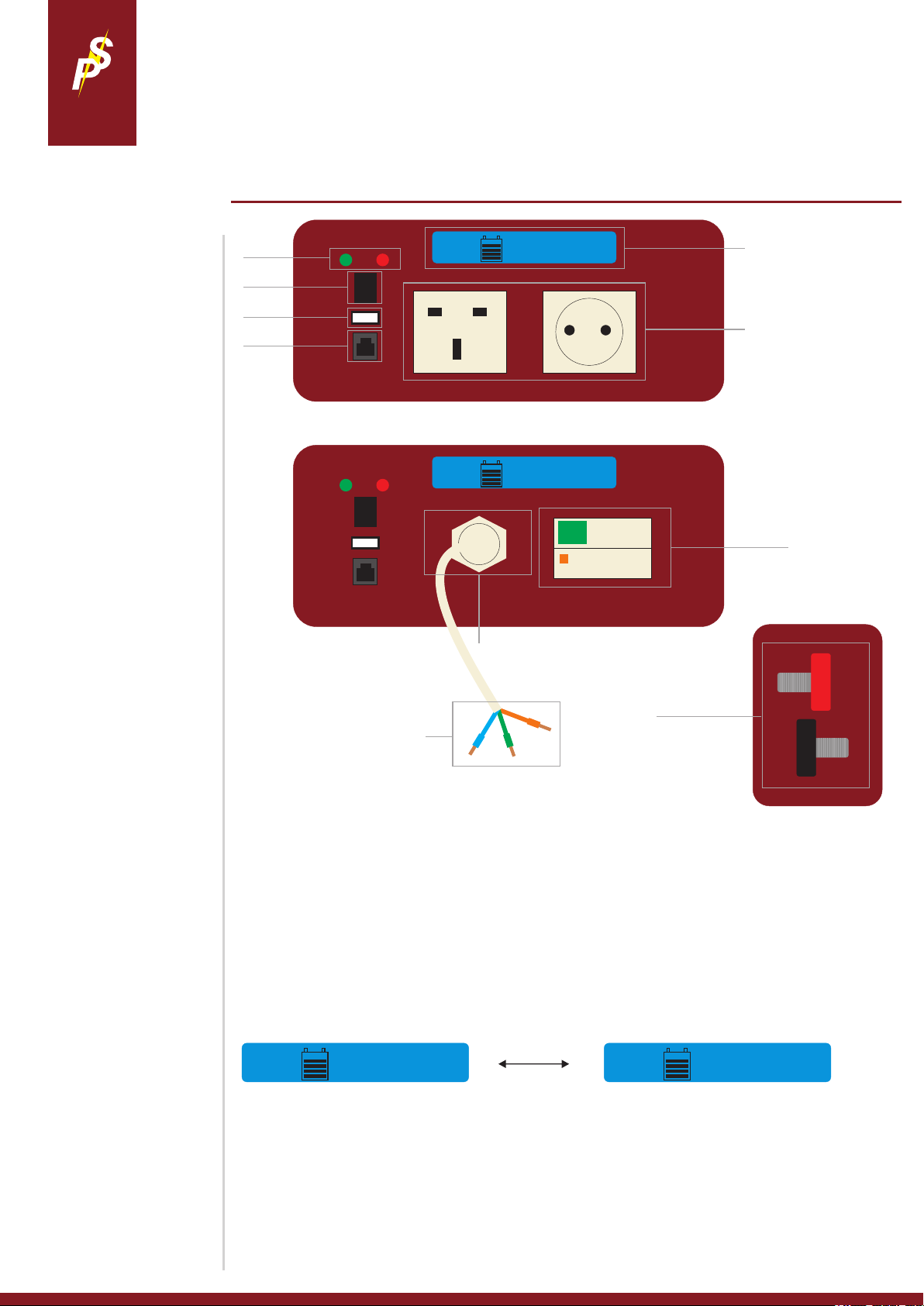
Remote control
with 5 meter
cable - optional
(Part No PSRC)
Part No:
PS121500
PS122000
PS123000
PS124000
PS241500
PS242000
PS243000
PS244000
PS482000
PS484000
PSRCD121500
PSRCD122000
PSRCD123000
PSRCD124000
PSRCD241500
PSRCD242000
PSRCD244000
EN55032:2012
EN60950-1 : 2006+A11
2009+A1
2010+A12
2011+A2:2013
PRIDE IN PERFORMANCE
www.sterling-power.com
www.sterling-power-usa.com
Warranty (2 years return to factory)
Copyright © 2022
Sterling Power
All Rights Reserved
RoHS
compliant
PRODUCT CODE : PSRC
PURE SINE WAVE INVERTER REMOTE
instructions

Contents page
Welcome
Legal Guidelines
Safety Guidelines
PS Series front panel
Functions and Features
Installation
Integrated Protections
Troubleshooting
Fuse ratings and cable ratings
Remote control - optional (PSRC)
Introduction
02
03
04
05
06
07
08
09
10
11
12
INTRODUCTION TABLE OF CONTENTS
CONTENTS 02
50% Black
80% Black
RAL 3003 R134 G26 B34
STERLING
POWER

INTRODUCTION
Welcome to the Sterling Power Products Owners Handbook for the product series ‘PS’, shorthand for ‘Pure
Sine’.
Please take your time to read and fully understand the contents of this Handbook. These guidelines are
developed with your safety and the products performance in mind and failure to follow or understand these
guidelines may lead to voiding the product warranty or even leading to damage or injury for you or your setup.
If you are unsure of any step or guideline then please consider reaching out to Sterling via our web contact form
or our phone service and we shall offer our support.
Thank you for choosing Sterling and we hope to serve your travels well.
This manual must be read throughout before installing this electronic device. Do not lose these instructions -
keep them safe. The most up to date instructions can be found on the Sterling Power website. Please refer to the
latest instruction manual before contacting Sterling. At Sterling, we endeavour to include all of the product
information that we can think of into the manual.
Installation of the electronic device must be carried out by qualified and trained personnel only. The personnel
must be familiar with the locally accepted guidelines and safety measures.
Welcome
Using this Handbook
WELCOME
INTRODUCTION 03
STERLING
POWER

SAFETY AND LEGAL
Your 100 % satisfaction is our goal. We realise that every customer and circumstance is unique. If you have a
problem, question, or comment please do not hesitate to contact us. We welcome you to contact us even after
the warranty and return time has passed.
Each product manufactured by Sterling Power comes with at least a 2 year limited factory warranty. Certain
Products have a warranty period of time greater than 2 years. Each product is guaranteed against defects in
material or workmanship from the date of purchase. At our discretion, we will repair or replace free of charge any
defects in material or workmanship that fall within the warranty period of the Sterling Power product. The
following conditions do apply:
- The original receipt or proof of purchase must be submitted to claim warranty. If proof cannot be located a
warranty is calculated from the date of manufacture.
- Our warranty covers manufacture and material defects. Damages caused by abuse, neglect, accident,
alterations and improper use are not covered under our warranty.
- Warranty is null and void if damage occurs due to negligent repairs.
- Customer is responsible for inbound shipping costs of the product to Sterling Power either in the USA or
England.
- Sterling Power will ship the repaired or warranty replacement product back to the purchaser at their cost.
If your order was damaged in transit or arrives with an error, please contact us ASAP so we may take care of the
matter promptly and at no expense to you. This only applies for shipping which was undertaken by our company
and does not apply for shipping organised by yourself. Please do not throw out any shipping or packaging
materials. All returns for any reason will require a proof of purchase with the purchase date. The proof of
purchase must be sent with the returned shipment. If you have no proof of purchase call the vendor who supplied
you and acquire the appropriate documentation.
To make a claim under warranty, call our customer care check telephone numbers on www.sterling-power.com
or www.sterling-power-usa.com. We will make the best effort to repair or replace the product, if found to be
defective within the terms of the warranty. Sterling Power will ship the repaired or warranty replacement product
back to the purchaser, if purchased from us.
Please review the documentation included with your purchase. Our warranty only covers orders purchased from
Sterling Power. We cannot accept warranty claims from any other Sterling Power distributor. Purchase or other
acceptance of the product shall be on the condition and agreement that Sterling Power USA LLC and Sterling
Power LTD shall not be liable for incidental or consequential damages of any kind. Some states may not allow
the exclusion or limitation of consequential damages, so, the above limitations may not apply to you.
Additionally, Sterling Power USA and Sterling Power LTD neither assumes nor authorizes any person for any
obligation or liability in connection with the sale of this product. This warranty is made in lieu of all other
obligations or liabilities. This warranty provides you specific legal rights and you may also have other rights,
which vary from state to state. This warranty is in lieu of all other, expressed or implied.
Copyright © 2022 Sterling Power. All rights reserved.
Reproduction, transfer, distribution or storage of part or all of the contents of this document is strictly prohibited. If
you wish to use all of this document, or excerpts from it, Sterling Power must be contacted.
Sterling Power can not accept liability for:
Ÿconsequential damage due to use of this device
Ÿpossible errors in the manuals and the results thereof
Please do not modify the device unless you have been instructed to do so by Sterling Power, directly. Product
modification shall be done at Sterling, when needed. Warranty shall be voided if personal attempts are made to
modify the device, without Sterling’s approval.
Warranty and Terms
Copyright and Plagiarism
Liability
Device Modification
LEGAL GUIDELINES
SAFETY AND LEGAL 04
STERLING
POWER

SAFETY AND LEGAL
Your Sterling Power product should only be utilised for it’s designated purpose. Use the Sterling Power PS
Inverter ONLY :
For DC to AC power conversion
With fuses protecting both the AC/DC cables
In a well ventilated, dry, dust-free and condensation free environment
When the Owners Handbook has been read and wholly understood
Ensure that the mains supply and battery leads are disconnected before transporting or moving the unit. No
liability can be accepted for damage in transit once equipment has been unpackaged. Store the product in a dry
environment, between –20°C to 60°C.
Refer to the battery manufacturer's manual for information on transportation, stowage, charge rates, recharging
and battery disposal for your battery care.
The device must be switched off during maintenance and all cables removed from the direct feed to or from the
unit. It must also be protected against unexpected switching off. Remove battery connections and ensure unit is
off. If repair is required, only use original parts. Unauthorised attempts to repair Sterling units will lead to the
warranty being voided. Only someone with adequate understanding of electronics and the unit itself should
attempt a repair.
Ensure your connections are good and clean and aim to protect your unit from humidity and water ingress.
Inverters can be heavy, do not lift unassisted.
Ensure that your model is correct for your intent. 110V/240V, 12V/24V/48V. Incorrect use can lead to damage.
Orientation is not critical to unit function, however may affect water ingress rating.
Place as close to the house/leisure bank in use as possible.
Ensure inverter is off during install.
Disconnect AC wires during install.
Connect AC output to a Residual Circuit Breaker (RCD) and current overload trips.
When installing DC cables, connect to the inverter first and then, via a fuse on the positive line, connect both
cables to the battery terminals in use.
Sterling recommend Multi Core Tri Rated AC cable
Install device in a well ventilated space for cooling purposes.
Do not expose the unit to snow, rain, water, spray, condensation, pollution etc.
Do not cover or obstruct the ventilation.
Device connects to common negative. Common negatives must be earthed.
In case of fire, use fire extinguisher equipment suitable for electrical fires.
Avoid all possibilities of reverse polarity or short circuiting.
Check cabling and connections frequently and ensure the connections are sufficient.
Always protect DC and AC cabling with the appropriate fusing.
Ensure the unit is adequately and safely mounted to prevent displacement and damage.
Always use a professional to install electrical products.
Ensure the product is correctly set up for your battery.
Turn the unit on before turning on the AC appliances connected to it.
Keep out of reach of children
All electrical appliances carry the risk of electrical shock. This equipment is designed to be used in combination
with a permanent energy source (the battery). Always turn the AC power off and disconnect the battery before
performing any maintenance or inspection.
Do NOT remove the panelling to inspect the internals unless expressly told to by Sterling. This is not a product
designed to be user-serviced.
Do NOT use the device in situations where there is danger of gas / dust / vapour explosions, or around potentially
flammable produce.
Product Guidelines
Transport and Storage
General Maintenance
Safety Precautions
WARNING :
SAFETY GUIDELINES
SAFETY AND LEGAL 05
STERLING
POWER
PRODUCT INFORMATION
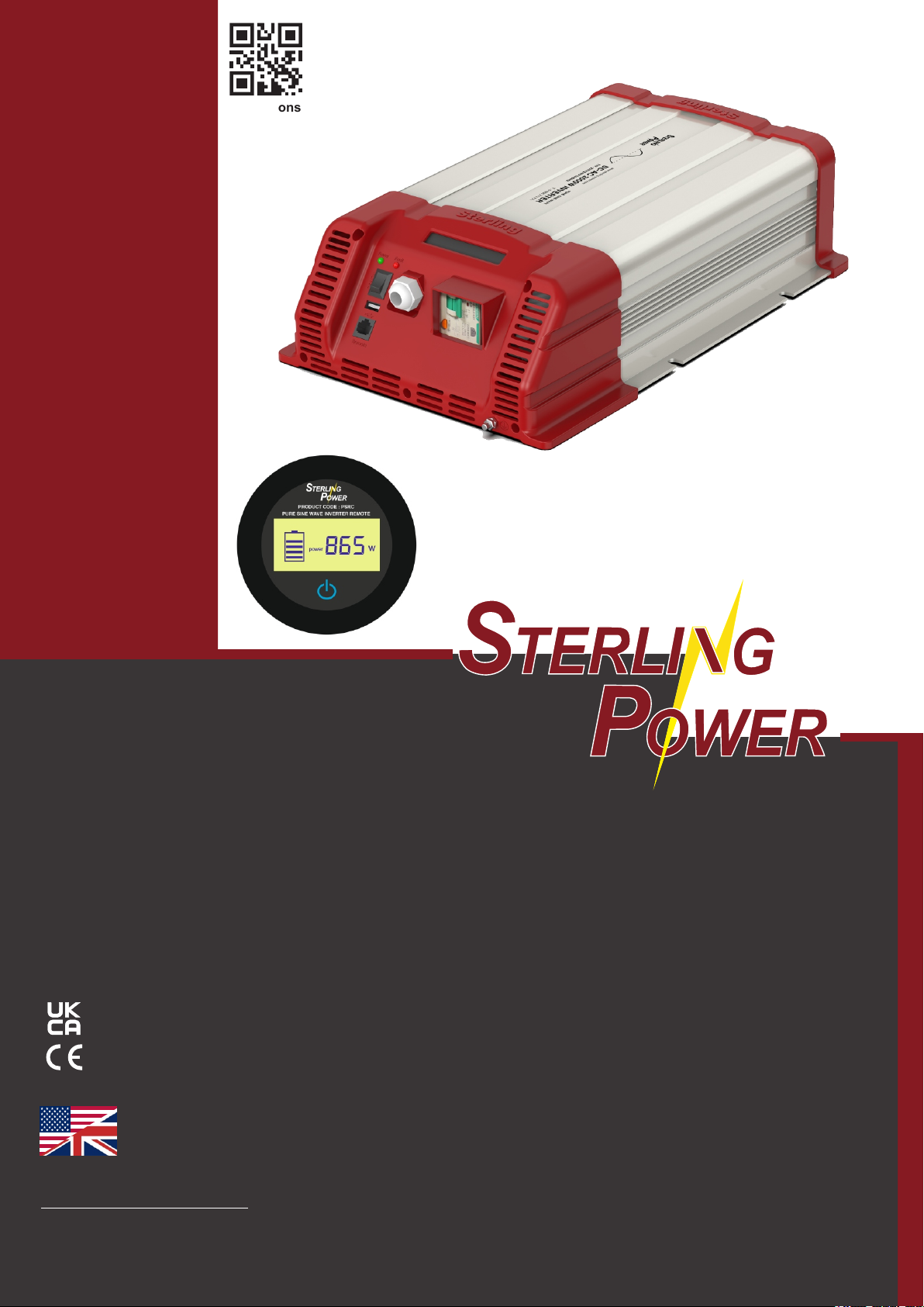
Twin Socket Model
RCD + hard wired model
LCD display screen
Front Panels
PRODUCT INFORMATION 06
STERLING
POWER
1.31 v
0
I
1.31 v
0
I
5
1
2
3
4
6
9
7
8
1) Green LED means unit on and working. Red LED means fault.
2) Simple toggle on/off switch
3) 5V 2.1A USB port
4) Remote port.
5) LCD screen - displays battery voltage, inverter wattage use and an estimated battery state of charge meter.
6) Twin socket - UK socket and Schuko Euro socket.
7) AC cable connection point - with AC cable extension
8) Live Earth Neutral - cable to be connected to AC distribution / sockets
9) RCD - Residual Current Device - a protection device designed to trip if there is leak in the neutral.
10) DC terminals - 8mm bolts. Red positive | Black Negative
1.31 v850W
The LCD display screen automatically toggles between battery voltage and AC output wattage. Both of these
values are good approximations, they are not 100% accurate.
The battery symbol (with the 5 bars) approximately indicates the state of charge of the battery. It makes this
decision based purely on the voltage. It is NOT an accurate representation of the SOC or health of the battery the
inverter is connected to. Check our power management panel (PMP series) for accurate Ah counting and battery
voltage readings.
10
Rear side / DC side
PRODUCT CODE : PSRC
PURE SINE WAVE INVERTER REMOTE
1.31 v
voltage
PRODUCT CODE : PSRC
PURE SINE WAVE INVERTER REMOTE
865w
power
cycles

Ensure you have read the manual completely before using this device. A full understanding of the capabilities of
the Sterling Power product is crucial to it’s continued performance and your safety.
This inverter converts a 12V or 24V or a 48V DC voltage into a usable AC voltage with a pure sine wave (100-
127V/220-240VAC). This inverter allows you to utilise a battery power source to supply power to equipment that
would require mains supply. The voltage for the input and the voltage for the output is dependent on the model.
Be aware that some products have power surges on initial engagement. Ensure that these start-up peaks are
within the inverters operatable range. Some peaks can be up to as much as 5 times the continuous power
consumption of an electrical product.
Prior to using the inverter ensure that all cables are mounted correctly and are secure. Never use the inverter
when cables are damaged. Ensure the inverter is [ON].
It is normal for the housing to get warm during operation. The fan will keep operation within a safe and efficient
range.
If you will not be using the inverter for a significant length of time you will benefit from disconnecting it from your
battery over the period.
POWER - GREEN - Battery connected and the switch is in the ON position.
FAULT - RED - Fault on the DC input or internal temperature
FAULT - RED BLINKING - Fault on the AC output
Cross reference with trouble shooting page for solution
All Sterling Power PS inverters have a 5V USB port. Maximum load is 2,1 amps.
PSRC is the product code for the Sterling Power Pure Sine Remote Control, the round-remote control intended
for use with the PS series of products. When it is connected it is important that the main switch on the inverter is in
the OFF position. When the inverter is in the OFF position the remote control can toggle power on and off.
The LCD screen displays the battery voltage (V), output power (W), battery state of charge, low voltage
protection alarm, over voltage protection alarm, overload protection alarm and the over temperature protection.
The fan is temperature and load influenced. At a certain load, dependent on model, the fan will engage
automatically. As internal temperature increases the fan will gradually increase in power.
PRODUCT INFORMATION
Introduction
Notes of Use
LED Indicators
USB Output
Remote Control
LCD Display
Cooling Fan
FUNCTIONS AND FEATURES
PRODUCT INFORMATION 07
STERLING
POWER

Ensure, if you are choosing to wall mount, that your mounting points are secure and sufficient to hold the weight
with the mounts you choose to use. Ensure that there is space for ventilation (minimum 10cm) to allow air
circulation. Ensure at least 2 of the available mounting supports are screwed in for install.
These units are neutral earth bonded, tying the neutral to the earth terminal. This gives 230V across the live and
neutral terminals but also from live to earth. This allows an RCD to operate safely as intended and is compliant
with hard wire installation requirements on vehicle installs.
All electrical installations should be carried out by a professional electrician. High voltages are a reality when
utilising an inverter and do have the potential to kill you. Ensure your input and output voltage needs are correct
for the model you have before continuing.
Sterling do not provide, by default, the cable necessary for your installation. We are of the belief that every install
is unique to the client and as such we cannot presume. Ensure that your cable thickness is sufficient and safe for
the current we can expect to move through it and ensure that you fuse your cable when connecting to a battery.
Red cable refers to the cable on the positive DC line. Black cable refers to the cable on the negative DC line.
1. Ensure all instructions have been adequately understood and you have ensured your personal safety.
2. Connect one side of the red cable to the positive DC terminals at the back of the inverter and one side of the
black cable to the negative DC terminals at the back of the inverter.
3. Tighten all connections firmly
4. Connect the remaining ends of cable to the battery. The red positive cable connects to the positive terminal on
the battery. The black negative cable connects to the negative terminal on the battery. These cables should be
correctly fused and the connection itself must be firm, tight and sufficient.
Do NOT reverse polarity the inverter (Positive to negative, negative to positive). This can destroy the inverter
and would not be covered under warranty.
The AC output ground must be connected with the grounding point for the connected equipment. The ground
connection on the inverter itself should be connected to the ground chassis on the vehicle with 6mm2 cable.
All Sterling PS inverters have two plug sockets. One Schuko (Euro) plug and one UK mains plug. Ensure that
your AC equipment does not exceed the power rating of the inverter. The inverter is at risk of becoming damaged
in the instance of power surges. This damage is not covered within the warranty as it constitutes invalid use.
Some users may wish to run this inverter in conjunction with other AC power supplies such as a mains supply or
a generator. This is NOT suitable. Having the inverter involved with other AC power supplies in a circuit will
damage the inverter and this is not covered by warranty. You must utilise a cross-over switch for use in these
situations.
An inverter MUST be safe for use. It may sometimes be difficult to obtain a good grounding/earth connection
however this is important to it’s safe operation. In some circumstances it is obligatory by law to have these units
safely grounded. To determine cable size / fuse size, refer to page 11.
PRODUCT INFORMATION
Mounting
Neutral Earth Bonding
Install Preface
Installation Instructions
Grounding
AC Equipment
Other AC Power Supplies
Legal Obligations
INSTALLATION
PRODUCT INFORMATION 08
Sterling Power Products
Copyright
1) UK socket
2) Euro socket
3) Power LED Green, on when inverter is Live.
4) Fault LED Red, if on there is a fault.
5) LED display
P = Power (W).
U = Voltage ( input DC ) = +/- 0.2V
6) Remote control (optional)
7) USB charger
8) On / off ( remote control )
9) Positive cable or positive connector in larger units
10) Negative cable or negative connector in larger units
11) Earth to chassis
12) Residual Current Breaker (earth trip)
13) AC output Live Earth Neutral connector, under flap.
Live
Neutral
Earth 230V
0V
230V
Netural Earth Bonded
Battery
+_
Battery
+_
Hard
wired
AC output
Ring Main
Earth
Installation
All electrical installations should be carried out by a professional electrician, any
doubts about installing this should be addressed to us as soon as possible. Do
not install this unit if you are not competent to do so, high voltages are involved
and have the potential to kill you. Ensure the inverter has the correct voltage
(DC and AC) and the correct power (W) for you vehicle / boat before installing.
Installation for twin socket:
1) Fit in a cool dry well ventilated space as close to the battery bank as possible.
2) Ensure at least 2 of the 5 mounting supports are screwed to the bulkhead.
3) Ensure both AC and DC cable is large enough to deal with high currents
4) Install DC cable fuse into each installation. Fuse size per unit in specification.
6) Secure the unit in position, fit DC fuse and isolation switch (not essential) as
required.
7) Do not reverse the DC cables. Connect the red cable to the positive
terminal and the black cable to the negative terminal of the battery, reverse
polarity could destroy the unit and would not be covered under warranty.
8) The standard sockets are rated at 13A. So you should NOT attempt to pull
more than 3000W through the sockets (irrespective of which SIB model you
have). If you require more power from your 4000W or 5000W model use
Hard wired installation
Underneath the plastic flap on the AC side (13) exposes the Live Earth and
Neutral connectors for hard wiring. Fasten the appropriate 3 cables to this
connector. Ensure the AC cable thickness is appropriate for the use.
Recommended cable sizes are on the next page. Hard wiring is appropriate to
maximise the potential of the 4000W and 5000W models, as we
recommend against pulling 3000W-5000W through the UK / Schuko
sockets.
In the event of this unit being installed into a ring main or extension power
circuit. The output voltage of this unit must never be on your AC system at
the same time as the 230V external mains line. If the output voltage is to be
used on a ring mains system, a suitable two-pole crossover switch must be
used. Failure to do this shall result in the destruction of this unit even if switched
off - this shall not be covered under warranty.
Sterling GANL Fuse holder
with correct GANL Fuse
( see specification )
Sterling
Isolation switch
(not essential)
Sterling
Isolation switch
(not essential)
Sterling GANL Fuse holder
with correct GANL Fuse
(Page 11 for cable and fuses)
earth to vehicle
chassis or boat
bonding system
earth to vehicle
chassis or boat
bonding system
Optional
remote control
with 10 meter
cable
(Part No SWR)
Wired AC
8888 6
12
34
87
5
910
11
13
AC side DC side
230V AC
(up to 5000W)
AC out
cover plate
Live
Earth
Netural
STERLING
POWER
1.31 v
850W
1.31 v
0
I
1.31 v
0
I
AC Sockets
to AC
distribution
(RCD model)

Sterling Power Products
Copyright
1) UK socket
2) Euro socket
3) Power LED Green, on when inverter is Live.
4) Fault LED Red, if on there is a fault.
5) LED display
P = Power (W).
U = Voltage ( input DC ) = +/- 0.2V
6) Remote control (optional)
7) USB charger
8) On / off ( remote control )
9) Positive cable or positive connector in larger units
10) Negative cable or negative connector in larger units
11) Earth to chassis
12) Residual Current Breaker (earth trip)
13) AC output Live Earth Neutral connector, under flap.
Neutral earth bonding. All of these inverters
are neutral earth bonded. This is where the
neutral is tied to the earth terminal giving 230V
across the live and neutral (more in keeping
with the actual mains configuration) but also
230V from live to earth. This allows an RCD to
safely operate and confirm with hard wire
installation requirements on vehicles and
boats.
Live
Neutral
Earth 230V
0V
230V
Netural Earth Bonded
Battery
+_
Using
Sockets
230V AC
(3000W max)
Battery
+_
Hard
wired
AC output
Ring Main
Earth
Installation
All electrical installations should be carried out by a professional electrician, any
doubts about installing this should be addressed to us as soon as possible. Do
not install this unit if you are not competent to do so, high voltages are involved
and have the potential to kill you. Ensure the inverter has the correct voltage
(DC and AC) and the correct power (W) for you vehicle / boat before installing.
Installation for twin socket:
1) Fit in a cool dry well ventilated space as close to the battery bank as possible.
2) Ensure at least 2 of the 5 mounting supports are screwed to the bulkhead.
3) Ensure both AC and DC cable is large enough to deal with high currents
4) Install DC cable fuse into each installation. Fuse size per unit in specification.
6) Secure the unit in position, fit DC fuse and isolation switch (not essential) as
required.
7) Do not reverse the DC cables. Connect the red cable to the positive
terminal and the black cable to the negative terminal of the battery, reverse
polarity could destroy the unit and would not be covered under warranty.
8) The standard sockets are rated at 13A. So you should NOT attempt to pull
more than 3000W through the sockets (irrespective of which SIB model you
have). If you require more power from your 4000W or 5000W model use
Hard wired installation
Underneath the plastic flap on the AC side (13) exposes the Live Earth and
Neutral connectors for hard wiring. Fasten the appropriate 3 cables to this
connector. Ensure the AC cable thickness is appropriate for the use.
Recommended cable sizes are on the next page. Hard wiring is appropriate to
maximise the potential of the 4000W and 5000W models, as we
recommend against pulling 3000W-5000W through the UK / Schuko
sockets.
In the event of this unit being installed into a ring main or extension power
circuit. The output voltage of this unit must never be on your AC system at
the same time as the 230V external mains line. If the output voltage is to be
used on a ring mains system, a suitable two-pole crossover switch must be
used. Failure to do this shall result in the destruction of this unit even if switched
off - this shall not be covered under warranty.
English or
Euro plug
Sterling GANL Fuse holder
with correct GANL Fuse
( see specification )
Sterling
Isolation switch
(not essential)
Sterling
Isolation switch
(not essential)
Sterling GANL Fuse holder
with correct GANL Fuse
( see specification )
earth to vehicle
chassis or boat
bonding system
earth to vehicle
chassis or boat
bonding system
Optional
remote control
with 10 meter
cable
(Part No SWR)
Wired AC
8888 6
12
34
87
5
12
910
11
13
AC side DC side
230V AC
(up to 5000W)
AC out
cover plate
Live
Earth
Netural
The PS series inverter has a number of protections dependant on the model.
In the instance of low DC voltage on the input an acoustic signal will engage.
Engage at Disengage at
12V Models : 10.5V +/-0.5V 11.5V +/-0.2V
24V Models : 21V +/-0.5V 23V +/-0.2V
48V Models : 42V +/-0.5V 46V +/-0.2V
If the input voltage continues to drop after the alarm signals the low voltage protection will engage. AC output is
shut down and the red fault indicator will trigger. The alarm will continue to sound. The inverter will automatically
restart when the voltage has risen sufficiently.
Shut down at Restart at
12V Models : 10V +/-0.5V 12.6V +/-0.2V
24V Models : 20V +/-0.5V 25.2V +/-0.2V
48V Models : 40V +/-0.5V 50.4V +/-0.2V
If the input voltage rises outside of safe parameters then the PS inverter will trigger its over-voltage protection.
The AC output will be shut down and the red fault indicator will trigger. When the input voltage has dropped to
safe levels the inverter will restart.
Shut down at Restart at
12V Models : 16V +/-0.5V 12.6V +/-0.2V
24V Models : 32V +/-0.5V 25.2V +/-0.2V
48V Models : 64V +/-0.5V 50.4V +/-0.2V
In rare instances the internal cooling provided by the fan may be insufficient. In these instances the temperature
protection feature will engage. This disables the AC output and the red fault indicator will engage. Once the
inverter has cooled again it will restart automatically.
The inverter will switch off the AC output if it detects a short circuit on the output side. The red fault indicator will
flash intermittently. Inverter will restart automatically when the fault is resolved
If the AC output is demanding power that is greater than the inverter is rated to safely provide the overload
protection will disconnect the output. The red fault indicator will flash intermittently. Once the problem is resolved
the inverter will restart.
In the instance that the protection is not quick enough to engage and you manage to damage the unit (either
through overload, over voltage, etc) this is not at fault of Sterling and the unit will not be liable for warranty.
Sterling Power is not liable for the potential degradation of your batteries. This may occur if you continually and
repeatedly drain your batteries down past their preferred guidelines.
PRODUCT INFORMATION
Protections
Low Voltage Warning
Low Voltage Protection
Over Voltage Protection
Temperature Protection
Short Circuit on Output
Overload Protection
Warranty Note
INTEGRATED PROTECTIONS
PRODUCT INFORMATION 09
STERLING
POWER

The acoustic warning implies low DC voltage on the input. Please charge your battery or supplement the load by
charging your battery while running the inverter.
A solid red fault light implies there is either an input fault or the temperature protection is active.
In the instance of an input fault you will likely register the input voltages from your battery as being too low or too
high. When the voltages return to normal levels the inverter will engage.
In the instance of the temperature protection causing the fault, please verify that the fan is working and that the
inverter has sufficient ventilation. If the inverter is located in an area of high ambient temperature and frequently
seems to have temperature trips, please consider relocating it into a cooler area.
A blinking red fault light implies there is an output fault. This will likely either be a short circuit or an overload.
Please safely attempt to check your AC appliances for a fault. When the fault is resolved the inverter will restart
automatically.
This can imply a number of potential faults and is largely due to using improper equipment. Please verify that
your battery capacity is sufficient to supply the requested load. Please verify that all of the connections between
the inverter and the battery are sufficient. Please verify that the cables in use are sufficient for your demand.
Please verify that the power being requested is within the rating of the inverter.
In the instance that all LEDs are off, please verify that you are receiving a valid voltage at the DC input terminals.
Please verify this with an independent voltmeter as read off of the terminals themselves. If you are getting a 0V
reading at these rear terminals then it is likely that a fuse has blown or your battery, if lithium, may have tripped.
There could be a connection failure somewhere between the inverter and your battery.
If you are getting your battery voltage at the DC terminals please verify that any fuses have not blown. Some
fuses allow a continuity reading even after they have blown. If you are getting a higher voltage than the inverter is
rated to, this could also explain the fault.
In the instance that none of the above seems to explain the problem and you are getting a valid voltage at the
inverter please verify that the inverter is turned ON. If the inverter is turned ON and you have valid voltages at the
terminals and the inverter is still not functioning or providing any feedback then please contact Sterling with
voltage readings ready to provide.
PRODUCT INFORMATION
Buzzer Alarm
Solid Red Fault Light
Blinking Red Fault Light
Green LED But No Output
No LEDs, No Function
TROUBLESHOOTING
TROUBLESHOOTING 10
STERLING
POWER

Sterling Power Products
Copyright
Your 100 % satisfaction is our goal. We realise that every customer
and circumstance is unique. If you have a problem, question, or
comment please do not hesitate to contact us. We welcome you to
contact us even after the warranty and return time has passed.
Product Warranty:
Each product manufactured by Sterling Power comes with at least a 2
year limited factory warranty. Certain Products have a warranty period
of time greater than 2 years. Each product is guaranteed against
defects in material or workmanship from the date of purchase. At our
discretion, we will repair or replace free of charge any defects in
material or workmanship that fall within the warranty period of the
Sterling Power product. The following conditions do apply:
- The original receipt or proof of purchase must be submitted to
claim warranty. If proof cannot be located a warranty is calculated
from the date of manufacture.
- Our warranty covers manufacture and material defects.
Damages caused by abuse, neglect, accident, alterations and
improper use are not covered under our warranty.
- Warranty is null and void if damage occurs due to negligent
repairs.
- Customer is responsible for inbound shipping costs of the
product to Sterling Power either in the USA or England.
- Sterling Power will ship the repaired or warranty replacement
product back to the purchaser at their cost.
If your order was damaged in transit or arrives with an error, please
contact us ASAP so we may take care of the matter promptly and at no
expense to you. This only applies for shipping which was undertaken by
our company and does not apply for shipping organised by yourself.
Please do not throw out any shipping or packaging materials. All
returns for any reason will require a proof of purchase with the
purchase date. The proof of purchase must be sent with the returned
shipment. If you have no proof of purchase call the vendor who
supplied you and acquire the appropriate documentation.
To make a claim under warranty, call our customer care check
telephone numbers on www.sterling-power.com or www.sterling-
power-usa.com. We will make the best effort to repair or replace the
product, if found to be defective within the terms of the warranty.
Sterling Power will ship the repaired or warranty replacement product
back to the purchaser, if purchased from us.
Please review the documentation included with your purchase. Our
warranty only covers orders purchased from Sterling Power. We
cannot accept warranty claims from any other Sterling Power
distributor. Purchase or other acceptance of the product shall be on
the condition and agreement that Sterling Power USA LLC and
Sterling Power LTD shall not be liable for incidental or consequential
damages of any kind. Some states may not allow the exclusion or
limitation of consequential damages, so, the above limitations may
not apply to you. Additionally, Sterling Power USA and Sterling Power
LTD neither assumes nor authorizes any person for any obligation or
liability in connection with the sale of this product. This warranty is
made in lieu of all other obligations or liabilities. This warranty
provides you specific legal rights and you may also have other rights,
which vary from state to state. This warranty is in lieu of all other,
expressed or implied.
Cable and Fuse sizes
Cable and fuse sizes are just recommendations. Every 3 metres
double the thickness of the cable. Keep cable runs as short as
possible. Fuses are recommended to protect the DC cabling, not
to protect our inverter.
Customer Service & Warranty
Inverter voltage thresholds
Input (VDC) 10.5V - 15.5V (21.0V - 31.0V)
Output (VAC) 230VAC +/- 10%
Low DC voltage alarm11.0V (22.0V)
Low DC voltage trip 10.5V (21.0V)
High DC voltage trip 16.0V (32.0V)
Faults
x1
On solid
x1
x2
x3
x4
x = quick flash(es), then 2 second pause, then quick flash(es) - this continues until fault is ameliorated.
FAULT LED status Alarm AC output Reset procedure
Inverter on (no faults) N/A
Low input V warning
on on charge up batteries to raise voltage - alarm stops
Low input V trip
on off charge up batteries to raise voltage - switch off then on
High input voltage off off reduce input voltage - switch off then on
Overload / Short Circuit off off reduce AC load / remove short - switch off then on
Over temp shutdown on off Inverter temp must reduce - switch off then on
On solid
Remote control operation: Remove all AC power appliance
from the output of the inverter. Switch the on/off switch on the
main inverter to the off position. Ensure the remote control switch
is in the off position. Insert the remote control unit into the remote
socket on the front of the inverter. The switch on the remote
control is now the one in charge (keep the local control switch off).
Optional Remote Control (part no. SWR)
4
Model DC fuse (A) DC Cable (mm2) AC Cable (mm2)
SIB12(24
)3000 400 (200) 90 (50) 1.50
SIR12(24
)4000 500 (250) 120 (70) 2.50
SIB12(24
)5000 600 (300) 2x70 (90) 2.50
All PS inverters have a 120-150% overload for up to 3 minutes. They have a 200% overload for 3 seconds.
All PS inverters are 90% efficient at full load, 95% efficient at 1/3 load.
All PS inverters have an operational ambient range of -10'C to +50'C
All PS inverters have an AC output voltage of 200~240VAC, 50/60Hz
Rated Power DC Voltage Current DC Cable Sizes DC Fuses
1500W 12V ~150A 35mm2 200A
2000W 12V ~200A 50mm2 250A
3000W 12V ~300A 70mm2 350A
4000W 12V ~400A 95mm2 450A
1500W 24V ~70A 25mm2 100A
2000W 24V ~100A 25mm2 140A
3000W 24V ~150A 50mm2 200A
4000W 24V ~200A 70mm2 250A
2000W 48V ~50A 16mm2 80A
4000W 48V ~100A 25mm2 120A
Rated Power DC Voltage Current DC Cable Sizes DC Fuses
1500W 12V ~150A 35mm2 200A
2000W 12V ~200A 50mm2 250A
3000W 12V ~300A 70mm2 350A
4000W 12V ~400A 95mm2 450A
1500W 24V ~70A 16mm2 100A
2000W 24V ~100A 25mm2 150A
4000W 24V ~200A 70mm2 250A
PRODUCT INFORMATION
Overload
Efficiency
Temperature
AC Output
PS121500
PS122000
PS123000
PS124000
PS241500
PS242000
PS243000
PS244000
PS482000
PS484000
PSRCD121500
PSRCD122000
PSRCD123000
PSRCD124000
PSRCD241500
PSRCD242000
PSRCD244000
SPECIFICATIONS AND CABLE THICKNESS AND FUSE RATING
CABLE SIZES AND FUSE RATINGS 11
Part No:
PS121500
PS122000
PS123000
PS124000
PS241500
PS242000
PS243000
PS244000
PS482000
PS484000
STERLING
POWER

PRODUCT CODE : PSRC
PURE SINE WAVE INVERTER REMOTE
1.31 v
voltage
PRODUCT CODE : PSRC
PURE SINE WAVE INVERTER REMOTE
865w
power
Voltage display - This is the DC voltage read
inside the inverter. It is not an accurate voltage
reading of your batteries.
REMOTE CONTROL
Remote Control
PSRC - optional
The PSRC comes with 10m of
cable and connects here.
If the inverter is powered up, the
green / yellow back light on the
remote shall illuminate displaying
voltage <-> power.
If the back light illuminates but
there is no display, try turning
your inverter off and on again.
Remote control dimensions
to scale
Remote Control Use with PS Series inverters
REMOTE CONTROL 12
STERLING
POWER
Power display - this is a simple AC voltage x
AC current calculation. It is a good estimation
of the AC power being consumed from the
inverter.
automatically
cycles between
On and off toggle switch - this button simply
switches the inverter on and off. In order to
engage the on/off function of the remote the
Inverter switch position needs to be ‘O’ - off.
Battery state of charge meter. This is a meter
that displays the estimated battery state. It
works purely from voltages. This is not a
reliable state of charge representation.
50mm - inner
66mm - outer
This manual suits for next models
17
Table of contents
Other Sterling Power Products Inverter manuals


Popular Inverter manuals by other brands

FRONIUS
FRONIUS Galvo 208-240 1.5-1 operating instructions

Sofar solar
Sofar solar 7KTLM-G3 user manual

DualLite
DualLite LSN Installation instructions and user manual

APsystems
APsystems YC600B installation manual

APsystems
APsystems YC1000-3-3 Installation and user manual

Solark
Solark 8K-2P-L installation guide


Powersmart
Powersmart DB9801 instruction manual

Qcells
Qcells Q.TRON M-G2.X Series Installation and operation manual

Delta
Delta PPM CT16 101 Quick Installation Guideline

FRONIUS
FRONIUS Primo 10.0-1 208-240 Installation

OutBack Power
OutBack Power FXR International Series installation manual

Power Master
Power Master SLU Series user manual