Sterling Power Products SIB12600 User manual
SterlingPower Products
Copyright
Please read these instructions before installation or use!
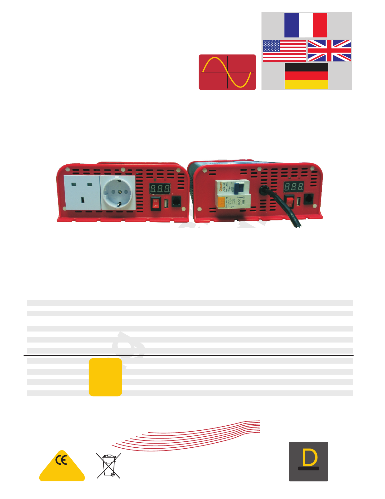
Option 1
Twin socket
adjustable between
Centre tapped earth
and Neutral earth bonding
Option 2
Model Centre tapped Earth Neutral earth bonded Remote Weight Size mm Cables Part number
12V 300 watt Twin sockets interchangeable between both Optional extra 1.4 kg 190x85x210L 1m DC 8 mm ring SIB12300
12V 600 watt Twin sockets interchangeable between both Optional extra 2.2 kg 190x85x250L 1m DC 8 mm ring SIB12600
12V 1000 watt Twin sockets interchangeable between both Optional extra 3.5 kg 190x85x300L 8 mm connection SIB121000
12V 1600 watt Twin sockets interchangeable between both Optional extra 3.6 kg 190x85x300L 8 mm connection SIB121600
12V 2000 watt Twin sockets interchangeable between both Optional extra 4.1 kg 190x85x300L 8 mm connection SIB122000
24V 300 watt Twin sockets interchangeable between both Optional extra 1.4 kg 190x85x210L 1m DC 8 mm ring SIB24300
24V 600 watt Twin sockets interchangeable between both Optional extra 2.2 kg 190x85x250L 1m DC 8 mm ring SIB24600
24V 1000 watt Twin sockets interchangeable between both Optional extra 3.5 kg 190x85x300L 8 mm connection SIB241000
24V 1600 watt Twin sockets interchangeable between both Optional extra 3.6 kg 190x85x300L 8 mm connection SIB241600
24V 2000 watt Twin sockets interchangeable between both Optional extra 4.1 kg 190x85x300L 8 mm connection SIB242000
12V 1000 watt with RCD Optional extra 3.5 kg 190x85x330L 8 mm connection SIBR121000
12V 1600 watt with RCD Optional extra 3.6 kg 190x85x330L 8 mm connection SIBR121600
12V 2000 watt with RCD Optional extra 4.1 kg 190x85x330L 8 mm connection SIBR122000
24V 1000 watt with RCD Optional extra 3.5 kg 190x85x330L 8 mm connection SIBR241000
24V 1600 watt with RCD Optional extra 3.6 kg 190x85x330L 8 mm connection SIBR241600
24V 2000 watt with RCD Optional extra 4.1 kg 190x85x330L 8 mm connection SIBR242000
Remote control ( fits all the above models ) 90 x 60 x 20 10 meter SWR
interchangeable between both
interchangeable between both
interchangeable between both
interchangeable between both
interchangeable between both
interchangeable between both
Pre-fitted
and wired
RCD option
with 1 meter
AC cable
Optional
remote control
with 10 meter
cable
Pure Sine Wave Inverters
Pro Power SB (R)
12V / 24V DC >> 230V AC
& 110V AC
technology
4
D
:
U
L
R
A
A
T
I
B
G
I
L
E
D
:
:
D
C
I
E
M
S
A
I
G
N
N
Y
D
ProDigital
RoHS
compliant
Sterling Power Products Ltd.
www.sterling-power.com
www.sterling-power-usa.com
Sterling Power Products
Pure
sine wave
output
RoHS
compliant
English
French
Deutsch
EN60950-1
EN55022: A2:2003 CLASS B
EN55024:2003
EN61000-3-2:2000
EN61000-3-3:1995/A1:2001
IEC61000-4-2:A2:2003
IEC61000-4-3:20002/A1:2002
IEC61000-4-4:2004
IEC61000-4-6:A1:2004
IEC61000-4-8:A1:2000
Pre wired RCD
adjustable between
Centre tapped earth
and Neutral earth bonding
SterlingPower Products
Copyright
888 888
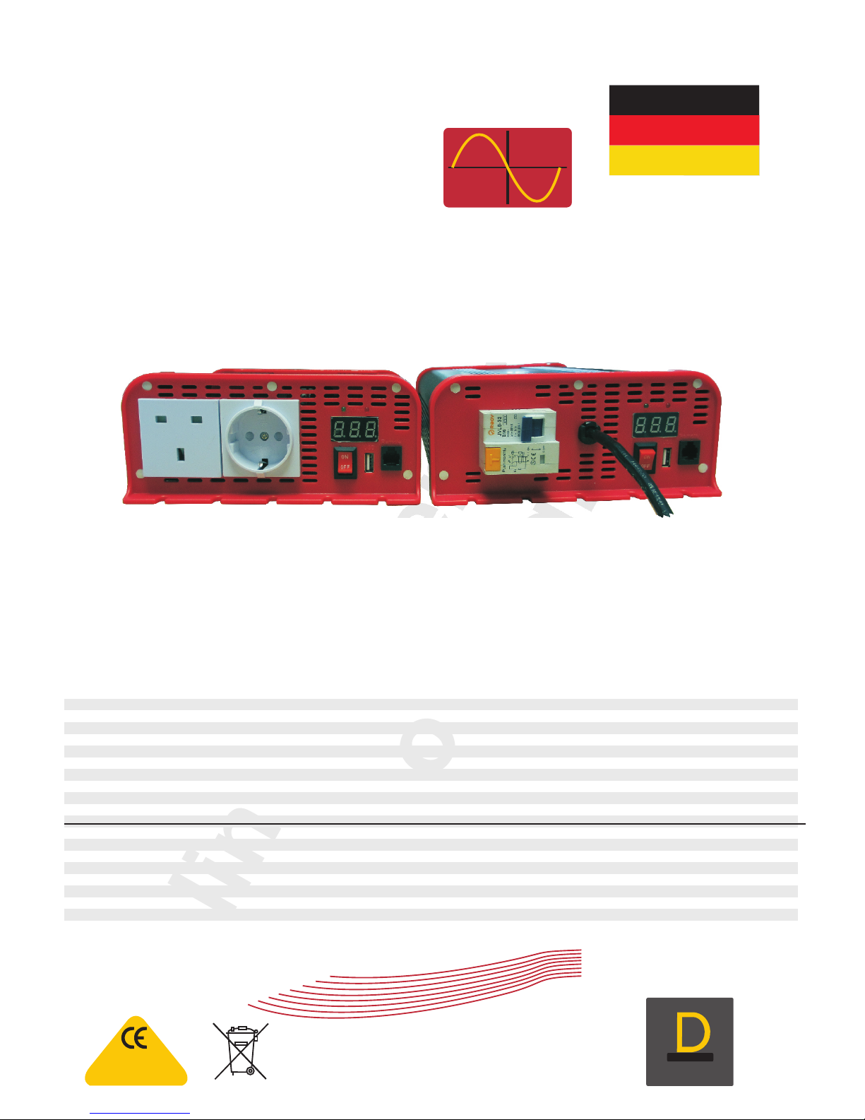
Standard inverter with dual sockets.
Earth adjustable between centre tapped
earth ( default ) and Neutral earth bonded
(simply add rear fuse for neutral earth bonding)
Pre-fitted RCD Model.
A 30 mA RCD pre-installed in unit
pre-wired for neutral earth bonding
to operate RCD.
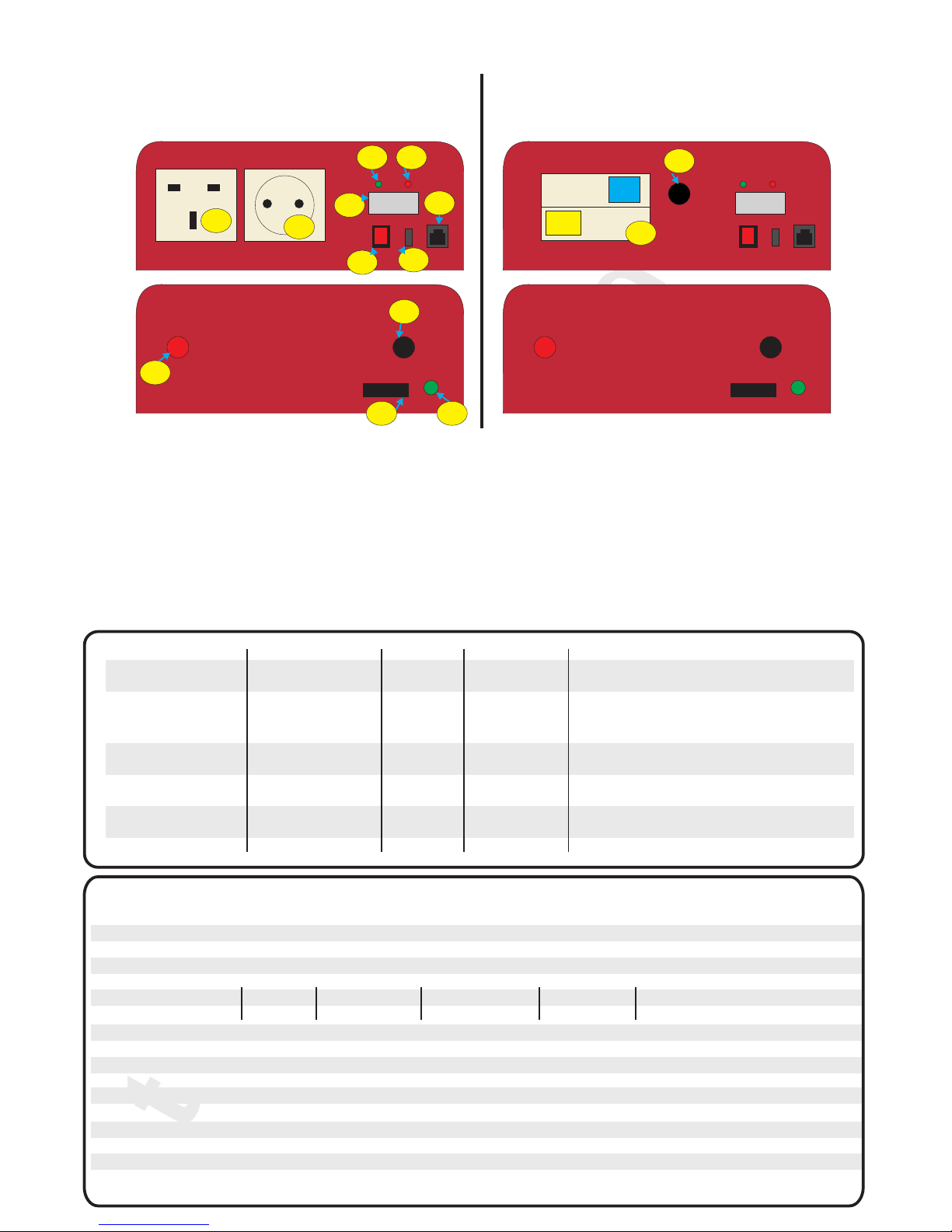
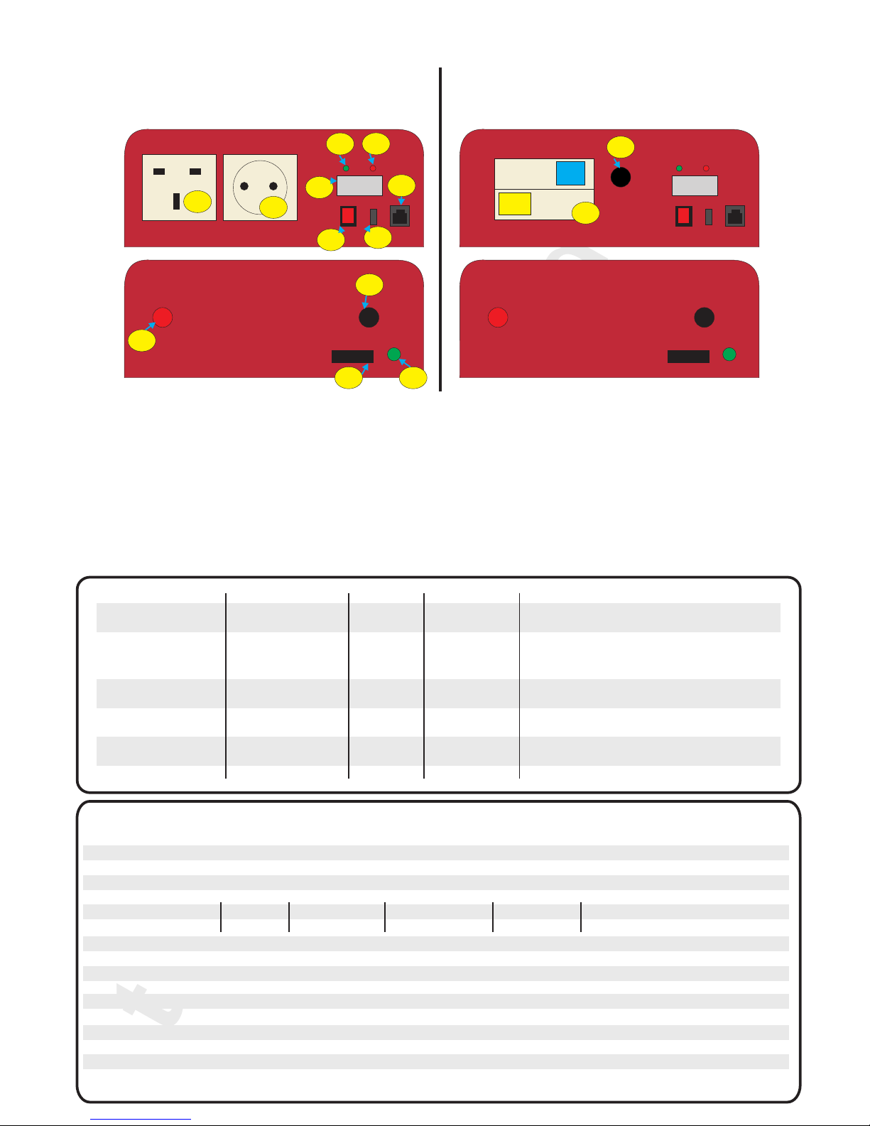
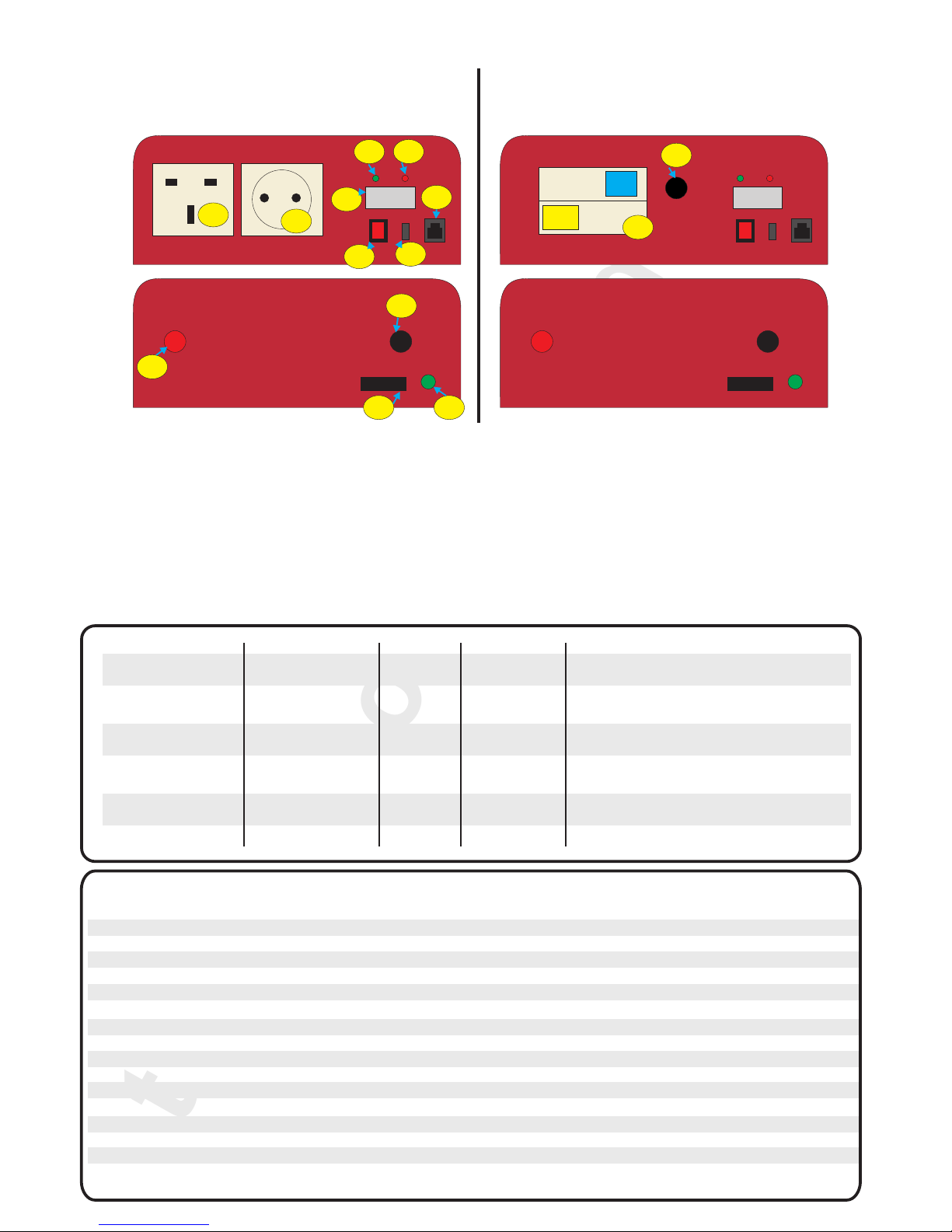
Front view Front view
Rear view Rear view
Option 1 Option 2
6
12
34
13
11
10
9
87
5
12
14
1) UK socket 7) USB charger
2) Euro socket 8) On / off ( remote control )
3) Power LED Green, on when inverter is Live. 9) Positive cable or positive connector in larger units
4) Fault LED Red, if on there is a fault. 10) Negative cable or negative connector in larger units
5) LED display ( -P- = Power, watts , not usable on low 11) Link for converting to neutral earth bonding
power loads, about +/- 10%, not very accurate just 12) Earth to chassis
approx ) 13) Residual Current Breaker ( earth trip )
( -U- = Voltage ( input DC ) = +/- 0.2V) 14) Pre-wired AC output cable
Fault Display i.e. 05 then unit over heat, restart
manually
6) Remote control ( optional )
Fault LED light Alarm AC output Reset required
Low input voltage Green on red off Yes Yes alarm stop when voltage increase
Warning
Low input trip Green on red on Yes No Charge batteries then switch unit off
and on to restart
High input voltage Green on red on No No Reduce input voltage then switch
off and on again to reset
Overload Shutdown Green on red on No No Reduce load, switch off and on to
restart
Over Temp shut Green on red on Yes No Unit must return to temp then switch
off and on to restart
Short circuit Green on red on No No Remove short unit will be on
Specification 300 watt 600 watt 1000 watt 1600 watt 2000 watt
Input voltage 12V model ( DC 11-15V ) 24V model ( DC 22-30V )
Output voltage 230V +/- 10% or 110V +/- 10%
Output frequency 230V version 50 Hz +/- 3 Hz 110V version 6
USB port DC 5V, 500 mA
Continuous power 300W 600W 1000W 1600W 2000W
Peak Power 600W 1200W 2000W 3200W 4000W
Digital display Input voltage and unit power in watts
Output wave form Pure sine wave
Distortion < 5%
Efficiency > 85%
No load Quiescent current 0.95A
Low voltage alarm (nominal) 12V = 10.5 V 24V = 21 V
Low voltage trip (nominal) 12V = 9.5 V 24V = 19 V
High voltage trip (nominal)
0 Hz +/- 3 Hz
12V = 15.5 V 24V = 31 V
Fan Operation, the fan will come on in the event of power exceeding 30% of unit rating or the internal exceeds 60C
Fuse Recommended 12V 60A
use Sterling ANL fuse 24V 30A 24V 50A 24V 70A 24V 125A 12V 180A
12V 100A 12V 150A 12V 250A 12V 350A
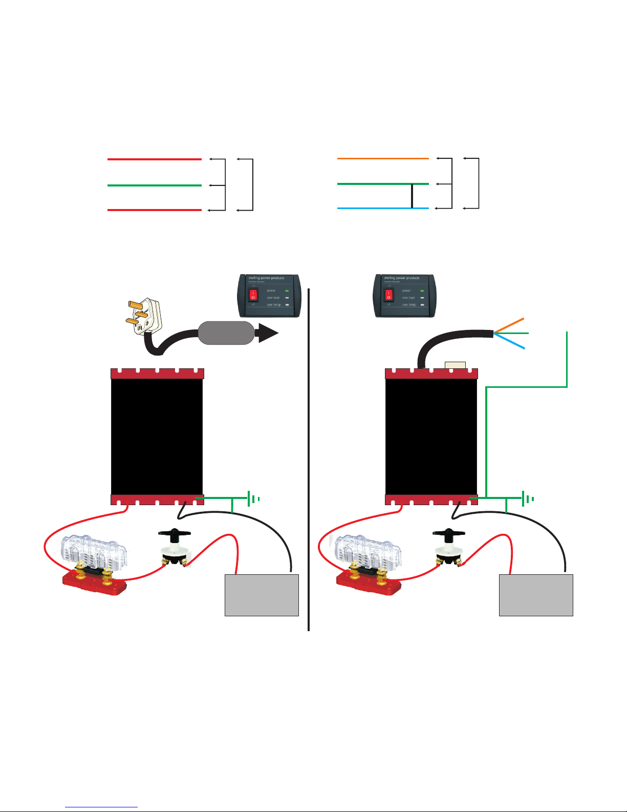
Fig 1 Fig 2
SterlingPower Products
Copyright
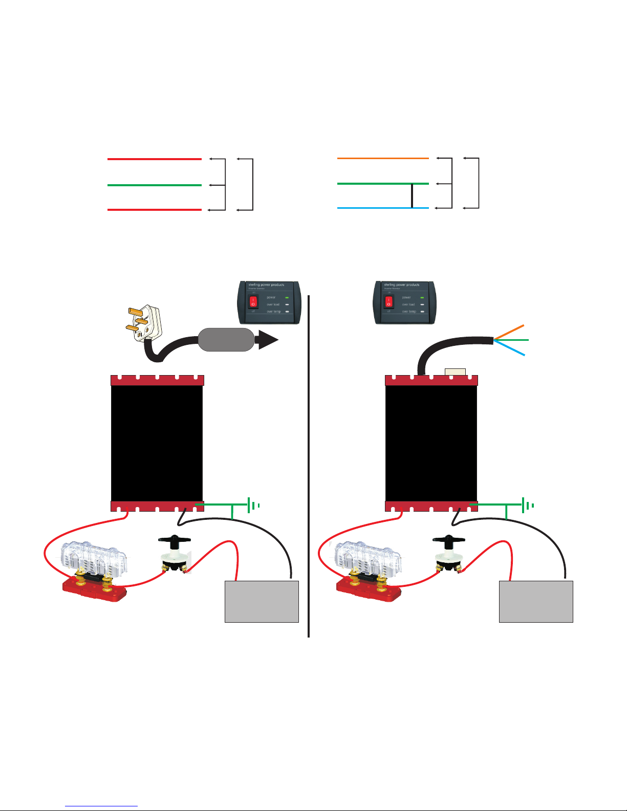
Earthing options for Option 1 and 2
Inverters tend to come in 2 different versions.
Centre tapped Earth ( fig 3 ) where, in effect, you have no real live and neutral but 2 lives and no neutral . You have 110V on either side of the
earth terminal making 220V across the two pins (live to “neutral”) but both pins are actually live. This is the most common and is default on this
range of inverters products . If no RCD is used this would probably be the best / safety option. The worst case event you will only get a 110V shock,
however, it is recommended that a RCD be used on all inverters but we recognise that a lot of people do not use RCDs* especially with smaller
units, so,alough ilegal to do so, we can only give the best advice to our customer base who adopt poor practices. It is Sterling Power Products actual
advice that all inverters should be used in conjunction with a RCD for ultimate safety and to comply with electrical installation codes. If you do fit a
RCD (as you are suppose to) a centre tapped inverter would be your safest option, but it will not operate a RCD safely it is, therefore, vital that if
you want to use a RCD in line with the AC output then the inverter unit must be converted from Centre tapped earth to Neutral earth bonded,
failure to do so will render the RCD ineffective.
Neutral Earth bonded ( fig 4 ), this is where the neutral is tied to the earth terminal giving 230V across the live and neutral ( more in keeping with
the actual mains configuration ) but also 230V from live to earth. This allows a RCD to safely operate and confirm with hard wire installation
requirements on vehicles and boats etc.
To convert Option 1 type unit from Centre tapped earth to Neutral earth bonded simply connect the enclosed link (small fuse) into position 11 on
Fig 1.
Live
Live
Earth 110 v
110 v
220 v
Centre tapped
Live
Neutral
Earth 220 v
0 v
220 v
Netural Earth Bonded
Sterling GANL Fuse holder
with correct GANL Fuse
( see specification )
Battery
+_
Sterling
Isolation switch
Option 1
Type
with twin
output
sockets
English or
Euro plug
IN Line RCD
230V AC
earth to vehicle
chassis or boat
bonding system
For RCD to work
convert to Neutral
Earth bonding
see above
Sterling GANL Fuse holder
with correct GANL Fuse
( see specification )
Battery
+_
Sterling
Isolation switch
Option 2
Type
with Pre
wired
RCD
230V AC
earth to vehicle
chassis or boat
bonding system
Live
Earth
Neutral
Fig 3
Fig 6
Fig 5
Fig 4
Optional
remote control
with 10m
cable
Optional
remote control
with 10m
cable
*RCD = Residual earth detector / Breaker / earth leak detector.
Pre-fitted RCD
Installation for Option 1 twin socket product
All electrical installations should be carried out by a professional electrician,
any doubts about installing this should be addressed to us as soon as
possible. Do not install this unit if you are not competent to do so, high
voltages are involved and have the potential to kill you. 6) Secure the unit in position, fit DC fuse and isolation switch as required in
position as per Fig 5. fuse size table on page 4
Installing Option 1 twin front sockets 7)
1) Fit in a cool dry well ventilated space as close to the battery bank as
possible.
2) Ensure at least 2 of the 5 mounting supports are screwed to the bulkhead.
3) Where cable is not supplied (1000-2000 units) or cable requires extending
ensure the cable is large enough to deal with the cable runs.
4) Install DC cable fuse into each installation fuse size per unit in
specification.
5)
Do not reverse the DC cables. Connect the red cable to the positive
terminal and the black cable to the negative terminal of the battery, reverse
Ensure that the inverter has the correct voltage for your boat or polarity could destroy the unit and would not be covered under warranty.
vehicle. 8) In the event of this unit being installed into a ring main or extension
power circuit. The output voltage of this unit must never be on your AC
system at the same time as the 230V external mains line. If the output
voltage is to be used on a ring mains system, a suitable two-pole crossover
switch must be used. Failure to do this will result in the destruction of this unit
even if switched off that the time and not covered under warranty
9) Only use products that are within the ability of the inverter to operate them,
also, take into account overload requirements on things like fridge motor as
by removing the small link cover at the rear of the unit under the
inserting the small fuse link into the rear of the unit under the neg
gable/connector, then insert the small fuse link and re cover, the unit is
now Neutral earth bonded . (Position 11 in Fig 1). This will ensure the
safe operation of the RCD.
It is good safety sense to use in conjunction with a RCD. If a RCD is
to be used then please convert this model to NEUTRAL Earth bonded
Ring Main
Earth

Sterling Power Products
Copyright
AC cable chart
Conductor size Current ½ for 110V
1.0 mm2 10 2400 watts
1.25 mm2 13 3120 watts
1.5 mm2 15 3600 watts
2.5 mm2 20 4800 watts
4.0 mm2 25 6000 watts
Max power (230V)
Amps AWG mm dia m
400 0000 11.6 106
320 000 10.4 85
285 00 9.2 66
250 0 8.2 52
200 1 7.3 42
180 2 6.5 34
150 3 5.8 27
135 4 5.2 21
120 5 4.6 16
100 6 4.1 13
90 7 3.6 10
70 8 3.3 8
60 9 2.9 6
50 10 2.5 5
m2
DC cables sizes, there is no fixed
simple chart for this as length of cable
run is a large part of the calculation.
I would work on every 3 meter / 10 ft then x 2
the thickness.
By far the best advice is to keep DC runs as
short as possible
In Line DC fuse
Fuse Recommended use Sterling ANL fuse & holder
300 watt 600 watt 1000 watt 1600 watt 2000 watt
12V 12V 12V 12V 12V
24V 24V 24V 24V 12V
60A 100A 150A 250A 350A
30A 50A 70A 125A 180A
and electric grinders etc. This could require a 500-1000% power increase terminal and the black cable to the negative terminal of the battery.
above the product rating i.e. a 80W fridge may require 800W to fire it up (a Reverse polarity could destroy the unit and would not be under warranty.
fridge is probably the hardest product to operate). 7) In the event of this unit being installed into a ring main or
extension power circuit The output voltage of this unit must never be
on your AC system at the same time as the 230V external mains line.
If the output voltage is to be used on a ring mains system, a suitable two-
pole crossover switch must be used. failure to do this will result in the
destruction of this unit even if switched off that the time and not covered
under warranty.
8) Only use products that are within the ability of the inverter to operate
them. Also, take into account overload requirements on things like fridge
motor and electric grinders etc. This could require a 500-1000% power
increase above the product rating, I.e. a 80W fridge may require 800W to
fire it up (a fridge is probably the hardest product to operate).
9)
1) Fit in a cool dry well ventilated space as close to the battery bank as
possible. Ensure that the inverter has the correct voltage for your boat or
vehicle.
2) Ensure at least 2 of the 5 mounting supports are screwed to the Remove all AC power
bulkhead. products from the output of the inverter. Switch the local on/off switch on
3) Where cable is not supplied (1000-2000 units) or cable requires the main inverter to the off position. Ensure the remote control switch is in
extending ensure the cable is large enough to deal with the cable runs. the off position. Insert the remote control unit into the remote socket on the
4) Install DC cable fuse into each installation fuse size per unit in front of the inverter. The switch on the remote control is now the one in
specification. charge ( keep the local control switch off ). switch the unit on and off using
5) Secure the unit in position, fit fuse and isolation switch as required in the remote.
position, as per Fig 5.
6) Do not reverse the DC cables! Connect the red cable to the positive
Remote control operation: Remove all AC power products from the
output of the inverter. Switch the local on/off switch on the main inverter to
the off position. Ensure the remote control switch is in the off position.
Insert the remote control unit into the remote socket on the front of the
inverter. The switch on the remote control is now the one in charge ( keep
the local control switch off ).
Installation for option 2 RCD version
This is a more dangerous product to install due to the 230V flying lead and
should be installed by a professional electrical engineer. Make sure the
product is switched off and the RCD is also switched off. Ensure the
naked AC fly lead is connected first before the DC. If the DC is
connected this lead will become live if not switched off, this is high
voltage AC and could kill.
This unit comes standard as centre tapped, and must be converter to
neutral earth bonding before installation Ensure the Neutral bonding
link is connected ( small fuse ) in position 11 in fig 1 ( same position on Fig
2, remove the cover and insert the small fuse in that link, the unit is
supplied without that link inserted. by inserting the link the unit becomes
neutral earth bonded, essential for the operation of the RCD
Remote control installation and operation:
Your 100 % satisfaction is our goal. We realise that every customer our company and does not apply for shipping organised by yourself.
and circumstance is unique. If you have a problem, question, or Please do not throw out any shipping or packaging materials.
comment please do not hesitate to contact us. We welcome you to
contact us even after the warranty and return time has passed. All returns for any reason will require a proof of purchase with the
purchase date. The proof of purchase must be sent with the returned
Product Warranty: shipment. If you have no proof of purchase call the vendor who
Each product manufactured by Sterling Power comes with at least a 2 supplied you and acquire the appropriate documentation.
year limited factory warranty. Certain Products have a warranty period of To make a claim under warranty, call our customer care check telephone
time greater than 2 years. Each product is guaranteed against defects in
material or workmanship from the date of purchase. At our discretion, we numbers on www.sterling-power.com or
will repair or replace free of charge any defects in material or www.sterling-power-usa.com. We will make the best
workmanship that fall within the warranty period of the Sterling Power effort to repair or replace the product, if found to be defective within the
product. The following conditions do apply: terms of the warranty. Sterling Power will ship the repaired or warranty
replacement product back to the purchaser, if purchased from us.
- The original receipt or proof of purchase must be submitted to
claim warranty. If proof cannot be located a warranty is calculated Please review the documentation included with your purchase. Our
from the date of manufacture. warranty only covers orders purchased from Sterling Power. We
- Our warranty covers manufacture and material defects. Damages cannot accept warranty claims from any other Sterling Power
caused by abuse, neglect, accident, alterations and improper use distributor. Purchase or other acceptance of the product shall be on the
are not covered under our warranty. condition and agreement that Sterling Power USA LLC and Sterling
- Warranty is null and void if damage occurs due to negligent Power LTD shall not be liable for incidental or consequential damages
repairs. of any kind. Some states may not allow the exclusion or limitation of
- Customer is responsible for inbound shipping costs of the consequential damages, so, the above limitations may not apply to
product to Sterling Power either in the USA or England. you. Additionally, Sterling Power USA and Sterling Power LTD neither
- Sterling Power will ship the repaired or warranty replacement assumes nor authorizes any person for any obligation or liability in
product back to the purchaser at their cost. connection with the sale of this product. This warranty is made in lieu
of all other obligations or liabilities. This warranty provides you specific
If your order was damaged in transit or arrives with an error, please legal rights and you may also have other rights, which vary from state
contact us ASAP so we may take care of the matter promptly and at no to state. This warranty is in lieu of all other, expressed or implied.
expense to you. This only applies for shipping which was undertaken by
Customer Service & Warranty
12 v unit alarms and trips for 24 v x 2
High V trip = 15-16V
Low V alarm = 10.2-10.8V
Low V trip= 9.2-9.8V
230 V AC
50 Hz

SterlingPower Products
Copyright
Lisez ces instructions avant l’installation s’il vous plaît.
Option 1
Prise double
Réglable, peut délivrer le courant
alternatif sous deux versions:
Deux phases actives et la terre.
Une phase active et la terre.
Option 2
Pré -câblé
Disjoncteur Différentiel intégré: DDR
Deux phases actives et la terre.
Une phase active et la terre.
Modèle deux phases actives, une phase active contrôle distance Poids Taille mm Câbles référence
12V 300 watt Deux prises interchangeable entre les deux Option 1.4 kg 190x85x210L 1m DC 8 mm ring SW12300
12V 600 watt Deux prises interchangeable entre les deux Option 2.2 kg 190x85x250L 1m DC 8 mm ring SW12600
12V 1000 watt Deux prises interchangeable entre les deux Option 2.0 kg 190x85x300L 1m DC 8 mm ring SW121000
12V 1600 watt Deux prises interchangeable entre les deux Option 3.6 kg 190x85x360L 8 mm connection SW121600
12V 2000 watt Deux prises interchangeable entre les deux Option 4.1 kg 190x85x400L 8 mm connection SW122000
24V 300 watt Deux prises interchangeable entre les deux Option 1.4 kg 190x85x210L 1m DC 8 mm ring SW24300
24V 600 watt Deux prises interchangeable entre les deux Option 2.2 kg 190x85x250L 1m DC 8 mm ring SW24600
24V 1000 watt Deux prises interchangeable entre les deux Option 2.0 kg 190x85x300L 1m DC 8 mm ring SW241000
24V 1600 watt Deux prises interchangeable entre les deux Option 3.6 kg 190x85x360L 8 mm connection SW241600
24V 2000 watt Deux prises interchangeable entre les deux Option 4.1 kg 190x85x400L 8 mm connection SW242000
12V 1000 watt avec DDR Option 2.0 kg 190x85x300L 1m DC 8 mm ring SWR121000
12V 1600 watt avec DDR Option 3.6 kg 190x85x360L 8 mm connection SWR121600
12V 2000 watt avec DDR Option 4.1 kg 190x85x400L 8 mm connection SWR122000
12V 1000 watt avec DDR Option 2.0 kg 190x85x300L 1m DC 8 mm ring SWR241000
12V 1600 watt avec DDR Option 3.6 kg 190x85x360L 8 mm connection SWR241600
12V 2000 watt avec DDR Option 4.1 kg 190x85x400L 8 mm connection SWR242000
Contrôle à distance (adaptabe à tous les modèles) 90 x 60 x 20 10 mètres SWR
interchangeable entre les deux
interchangeable entre les deux
interchangeable entre les deux
interchangeable entre les deux
interchangeable entre les deux
interchangeable entre les deux
Sécurité
DDR
préinstallé
avec 1mètre
de câble
Option
contrôleur à distance
avec 10 mètres
de câble
Convertisseur pur sinus
Pro
Power SB
12V / 24V Continu >> 230V Alternatif
& 110V Alternatif
technology
4
D
:
U
L
R
A
A
T
I
B
G
I
L
E
D
:
:
D
C
I
E
M
S
A
I
G
N
N
Y
D
ProDigital
RoHS
compliant
Sterling Power Products Ltd.
www.sterling-power.com
www.sterling-power-usa.com
Sterling Power Products
Pure
sine wave
output
RoHS
compliant
SterlingPower Products
Copyright
888 888
Standard, convertisseur avec deux prises.
Réglable entre: deux phases actives et la terre,
une phase active et la terre.
(Il suffit d’ajouter un fusible à l’arrière de l’appareil)
Pré câblé avec disjoncteur différentiel
Un DDR 30mamp est pré-installé dans l’appareil
pré-câblé, une phase active et neutre
pour que le DDR fonctionne.
Vue de face vue de face
Vue arrière Vue arrière
Option 1 Option 2
6
12
34
13
11
10
9
87
5
12
14
1) Prise britannique 8) On / off (Mise en marche)
2) Prise européenne 9) Câble positif ou borne positive(en fonction de la
3) LED verte de puissance, active si le convertisseur puissance du convertisseur)
fonctionne. 10) Câble négatifs ou borne négative(en fonction de la
4) LED rouge détectant un problème. Active en cas puissance du convertisseur)
d’anomalie. 11) Lien pour modifier le courant alternatif produit (une
5) LED affichage ( -P- = Puissance, watts +/- 5% ) phase active ou deux phases actives)
( -U- = Voltage ( Entrée CC ) = +/- 0.2V) 12) Terre, vers le châssis.
Affichage problème (voir tableau ci dessous) 13) Disjoncteur différentiel intégré
6) Contrôle à distance ( option ) 14) Câble sortie courant alternatif.
7) chargeur USB
Erreur Etat LED Alarme Sortie AC Réinitialisation
Alarme Tension
entrée faible
Tension entrée Verte on, rouge on oui non Charger la batterie, puis éteindre
trop basse et rallumer l’appareil.
Tension entrée haute Verte on, rouge on Non Non Réduire la tension entrée, éteindre
l’appareil et le rallumer.
Coupure surcharge Verte on, rouge on Non Non Réduire la charge, éteindre et rallumer.
pour redémarrer
Coupure température Verte on, rouge on oui Non L’appareil doit revenir à une température
haute normale ensuite éteindre et rallumer.
Court-circuit Verte on, rouge on
Verte on rouge off oui oui L ’alarme s’arrête quand la tension augmente
Non Non Eliminer le court-circuit, l’appareil fonctionnera
Specifications 300 watt 600 watt 1000 watt 1600 watt 2000 watt
Tension entrée modèle12V ( CC 11-15V ) modèle 24V ( CC 22-30V )
Tension sortie 230V +/- 10% ou 110V +/- 10%
Fréquence sortie version 230V 50 Hz +/- 3 Hz version 110V 6
Port USB CC 5V, 500 mA
Puissance délivrée 300W 600W 1000W 1600W 2000W
Puissance pic 600W 1200W 2000W 3200W 4000W
Affichage digital Tension entrée et puissance en watts
Signal sortie Pur sinus
Distortion < 5%
Efficacité > 85%
Courant passif admis 0.95A
Alarme sous-tension 12V = 10.5 V +/- 0.3V 24V = 21 V
Arrêt dû à sous-tension 12V = 9.5 V 24V = 19 V
Arrêt dû à sur-tension
0 Hz +/- 3 Hz
12V = 15.5 V 24V = 31 V
Ventilateur actif si la puissance demandée dépasse de 30% la capacité ou si la température interne dépasse 60 °.
Fusible recommandé 12V 60A
utiliser Sterling ANL 24V 30A 24V 50A 24V 70A 24V 125A 12V 180A
12V 100A 12V 150A 12V 250A 12V 350A
+/- 0.3V
+/- 0.3V +/- 0.3V
+/- 0.3V +/- 0.3V
Fig 1 Fig 2
SterlingPower Products
Copyright
Mises à la terre pour l’option 1
Les convertisseurs se présentent sous 2 versions différentes.
Deux phases actives ( fig 3 ) Dans ce cas, il n’y a pas un fil de phase et un fil neutre, mais deux fils de phase. Chacun de ces fils est à une
tension de 110 volts par rapport au fil de terre, la tension entre les deux fiches est alors de 220 volts, les deux fiches sont actives. Il s’agit du
montage le plus commun, c’est le montage par défaut installé sur l’option 1: le modèle avec deux prises fixées sur l’appareil. Si vous n’utilisez pas
de Dipositif Différentiel Résiduel (DDR) c’est probablement l’option présentant les meilleures conditions de sécurité, au pire des cas le choc
électrique sera sous une tension de 110 Volts. Nous précisons toutefois qu’il est très fortement recommandé d’utiliser une protection basée sur
un DDR (disjoncteur différentiel) sur tous les convertisseurs. Le conseil de Sterling est d’équiper tous les convertisseurs, même les plus
petits, de système de protection DDR afin de garantir votre sécurité. Si vous utilisez une protection DDR la sortie courant alternatif du
convertisseur doit impérativement être réglée avec une phase active et un fil neutre, il est important de modifier ce paramètre sinon la protection ne
fonctionne pas.
Un fil actif et un neutre ( fig 4 ), Le fil neutre est sous une tension nulle, la tension entre la phase et le neutre est de 230 V, la tension est
également de 230 entre la phase et la terre. Cette configuration permet l’utiisation du système de protection différentiel (DDR), les conditions de
sécurité exigées par les équipements électriques des bateaux et les véhicules sont alors respectées.
Actif
Actif
Terre 110 v
110 v
220 v
Deux phases actives
Actif
Neutre
Terre 220 v
0 v
220 v
Une phase active
Boîtier fusible Sterling GANL
muni du fusible correct GANL
( voir spécifications )
Batterie
+_
Interrupteur isolant
Sterling
Option 1
deux prises
en sortie
Prise Anglaise
ou Européenne
DDR en ligne
230V CC
Terre, vers le
chassis du véhicule
ou la ligne de terre
du bateau
Pour que la protection DDR
fonctionne modifier le réglage
et paramétrer
une phase active et un neutre
Boîtier fusible Sterling GANL
muni du fusible correct GANL
( voir spécifications )
Batterie
+_
Interrupteur isolant
Sterling
Option 2
Système DDR
précâblé
230V CC
Terre, vers le
chassis du véhicule
ou la ligne de terre
du bateau
Phase
Terre
Neutre
Fig 3
Fig 6
Fig 5
Fig 4
Ecran de contrôle
en option
avec 10m
câble
Ecran de contrôle
en option
avec 10m
câble
DDR = Disjoncteur différentiel Résiduel/détecteur fuite à la terre.
Système DDR fixé
4) Installez des fusibles sur les câbles de courant continu pour chaque
Installation de l’option 1, (produit muni de deux installation en respectant les spécifications.
prises). 5) Pour des raisons de sécurité électrique il est conseillé d’utiliser
Toute installation électrique doit être réalisée par un électricien l’appareil avec une protection DDR, il faut alors convertir l’appareil pour
professionnel, faites-nous part de vos hésitations au sujet de votre qu’il fournisse un courant alternatif avec une phase et un neutre, en
installation dès que possible. n’installez pas ce produit si vous n’êtes insérant le fusible à l’arrière de l’appareil (position 11 fig1).
pas compétent, des courants électriques de haute tension sont 6) Sécurisez l’appareil en position, installez des fusibles et un
produits, ils peuvent tuer. interrupteur isolant conformément à la figure 5.
7)
1) Installez dans un espace frais et bien ventilé, aussi près que
possible du parc de batteries. Assurez-vous que le convertisseur a
une tension adaptée à votre bateau ou à votre véhicule.
2) Assurez-vous qu’au moins 2 des 5 supports sont vissés sur la
cloison.
3) Quand les câbles ne sont pas fournis (Appareils 1000W-2000W) ou
si vous avez besoin de câbles supplémentaires, assurez-vous que les
câbles ont un diamètre suffisant.
N’inversez pas les câbles de courant continu. Connectez le
Installation de l’option 1, (produit muni de deux prises. câble rouge à la borne positive de la batterie et le câble noir à la borne
négative de la batterie. Inverser les polarités peut détruire l’appareil, ce
dommage ne sera pas couvert par la garantie.
8) Si l’appareil est monté dans un circuit pouvant être alimenté
par le courant alternatif du rèseau électrique l’appareil ne doit
pas entrer en contact avec l’alimentation électrique extérieure. Un
commutateur adapté, 3 positions, doit être utilisé. Même si
l’appareil est éteint il peut être endommagé. La destruction ne sera
alors pas prise en charge par la garantie.

SterlingPower Products
Copyright
Câbles C. Alternatif puissance max(230V)
Taille conducteur Courant ½ for 110V
1.0 mm2 10 Amp 2400 watts
1.25 mm2 13 Amp 3120 watts
1.5 mm2 15 Amp 3600 watts
2.5 mm2 20 Amp 4800 watts
4.0 mm2 25 Amp 6000 watts
Amps Awg mm dia m
400 0000 11.6 106
320 000 10.4 85
285 00 9.2 66
250 0 8.2 52
200 1 7.3 42
180 2 6.5 34
150 3 5.8 27
135 4 5.2 21
120 5 4.6 16
100 6 4.1 13
90 7 3.6 10
70 8 3.3 8
60 9 2.9 6
50 10 2.5 5
m2
Taille des câbles en courant continu,
Il n’y a pas de règle définitive, la longueur du câble
intervient pour une large part dans le calcul
On peut utiliser approximativement cette règle:
chaque fois que la longueur augmente de 3 mètres,
on mutiplie le diamètre par 2
Le meilleur conseil est de réduire
au maximum la longueur de ces câbles
Fusible courant continu
Fusibles recomandés, fusibles Sterling ANL
300 watt 600 watt 1000 watt 1600 watt 2000 watt
12V 12V 12V 12V 12V
24V 24V 24V 24V 12V
60A 100A 150A 250A 350A
30A 50A 70A 125A 180A
9) Vous devez utiliser uniquement des appareils électriques dont la 4) Installez des fusibles sur les câbles de courant continu pour chaque
puissance est adaptée à votre convertisseur. Il faut aussi tenir compte de installation en respectant les spécifications.
la puissance suppémentaire nécessaire au démarrage d’un moteur 5) Installez des fusibles et un interrupteur isolant conformément à la fig 5
électrique, le moteur d’un réfrigérateur, d’un mixeur, par exemple, 6) N’inversez pas les câbles de courant continu. Connectez le câble
L’augmentation de puissance nécessaire peut aller jusqu’à 500-1000% des rouge à la borne positive de la batterie et le câble noir à la borne négative
caractéristiques du produit. Un réfrigérateur de 80 watts peut nécessiter de la batterie. Inversez les polarités peut détruire l’apparei..
une puissance de 800 watts au départ, le réfrigérateur est probablement le 7) Si l’appareil est monté dans un circuit pouvant être alimenté par le
produit le plus difficile à contrôler. courant alternatif du réseau électrique l’appareil ne doit pas entrer
en contact avec l’alimentation électrique extérieure. Un interrupteur
adapté, 3 positions, doit être utilisé. Même si l’appareil est éteint il
peut être endommagé. La destruction ne sera pas prise en charge par la
garantie.
8) Vous devez utiliser uniquement des appareils électriques dont la
puissance est adaptée à votre convertisseur. Il faut aussi tenir compte de
la puissance supplémentaire nécessaire au démarrage d’un moteur
électrique, le moteur d’un réfrigérateur, d’un mixeur par exemple,
L’augmentation de puissance nécessaire peut aller jusqu’à 500-1000%
des caractéristiques du produit. Un réfrigérateur de 80 watts peut
nécessiter une puissance de 800 watts au départ, le réfrigérateur est
probablement le produit le plus difficile à contrôler.
9) Vérifiez que le fusible est en position 11 figure 1. Pour des raisons
légales le produit est vendu sans cette liaison, il faut l’installer pour que le
courant alternatif fourni soit adapté au système de protection différentiel.
1) Installez le convertisseur dans un espace frais et bien ventilé, aussi près Installation de l’écran de contrôle à distance: Débranchez tous les
que possible du parc de batteries. Assurez-vous que le convertisseur a une appareils utilisant le courant alternatifs du convertisseur. Mettez
tension adaptée à votre bateau ou à votre véhicule. l’interrupteur du convertisseur sur off. Assurez-vous que l’interrupteur de
2) Assurez-vous qu’au moins 2 des 5 supports sont vissés sur la cloison. l’écran de contrôle est sur off. Branchez alors l’écran de contrôle à
3) Quand les câbles ne sont pas fournis (Appareils 1000W-2000W) ou si distance sur la prise adaptée à l’avant de l’appareil. L’interrupteur de
vous avez besoin de câbles supplémentaires, assurez-vous que les câbles l’écran de contrôle est alors actif, laissez l’interrupteur de l’appareil sur off.
ont une section suffisante.
Installation de l’écran de contrôle à distance: Débranchez tous les
appareils utilisant le courant alternatifs du convertisseur. Mettez
l’interrupteur du convertisseur sur off. Assurez vous que l’interrupteur de
l’écran de contrôle est sur off. Branchez alors l’écran de contrôle à distance
sur la prise adaptée à l’avant de l’appareil. L’interrupteur de l’écran de
contrôle est maintenant actif, laissez l’interrupteur de l’appareil sur off.
Installation pour l’option 2 avec protection différentiel
Ce produit est plus dangereux à installer la tension est directement de 230
Volts sur les câbles de sortie, il doit être installé par un électricien averti.
Assurez-vous que le produit est sur la position off, que le disjoncteur
différentiel est aussi sur off. Il faut commencer par connecter les
câbles dénudés de la sortie courant continu. Ces fils sont alimentés
dès que l’appareil est connecté au courant continu, la tension est
alors de 230 Volts et peut tuer.
Votre satisfaction à 100 % est notre but.
Garanties du produit:
pas cette preuve demandez au vendeur qui vous a fourni la matériel
Nous savons que chaque consommateur est unique. Si vous avez un de vous en fournir une nouvelle.
problème, une question, un commentaire n ’hésitez pas à nos contacter, Pour faire une réclamation sous garantie, vérifier le numéro de
même si la période de garantie est terminée. téléphone sur internet. Nous ferons les meilleurs efforts pour remplacer
ou réparer le produit, si il est défectueux suivant les critères de la
Chaque produit fabriqué par Sterling est vendu avec une garantie d ’au garantie.
moins 2 ans, comptée à partir de la date d ’achat. Chaque produit est
garantie contre des défauts dans les matériaux ou des défauts de
fabrication. Nous choisirons de remplacer ou de réparer le produit
défectueux pendant la période de garantie.
Les conditions suivantes s ’appliquent:
- La preuve de l ’achat doit être fournie, sinon la période de
garantie commence à la date de fabrication de l ’objet.
- Notre garantie couvre les défauts dans les matériaux et dans la
fabrication. Les dommages causés par des négligences, des abus,
des accidents, des altérations, une mauvaise utilisation ne sont pas
couverts par notre garantie.
- La garantie ne s ’applique pas si les dommages proviennent
d ’une mauvaise réparation.
- Le consommateur est redevable des frais d ’envoi du produit.
- Sterling Power renverra le produit à ses frais
Si votre produit a été endommagé pendant le transport, ou si il n ’arrive
pas à la bonne destination n ’hésitez à nous contacter rapidement, nous
pouvons régler le problème.
Ceci ne s ’applique que pour le transport organisé par notre compagnie.
Il est préférable de ne pas jeter l ’emballage du produit.
Tout retour doit être accompagné d ’une preuve d ’achat. Si vous n ’avez
Service client& Garantie
SterlingPower Products
Copyright
Bitte lesen Sie unbedingt die Anleitung vor der Installation und Betrieb.
Option 1
2 Steckdosen
Auswahl zwischen
Mittelabgriff oder
Standard (neutral = Schutzleiter)
Option 2
Kabelausgang
inkl. 30mA FI
Mittelabgriff oder
Standard (neutral = Schutzleiter
Model Mittelabgriff oder Fernbedienung Gewicht Maße mm Kabel Artikel-Nr
neutral-Schutzleiter
12V 300W UK + Deutsche Steckdose wechselbar optional 1.4 kg 190x85x210L 1m Ringterminal (8mm) SIB12300
12V 600W UK + Deutsche Steckdose wechselbar optional 2.2 kg 190x85x250L 1m + Ringterminal (8mm) SIB12600
12V 1000W UK + Deutsche Steckdose wechselbar optional 3.5 kg 190x85x300L 8mm Anschlussbolzen SIB121000
12V 1600W UK + Deutsche Steckdose wechselbar optional 3.6 kg 190x85x300L 8mm Anschlussbolzen SIB121600
12V 2000W UK + Deutsche Steckdose wechselbar optional 4.1 kg 190x85x300L 8mm Anschlussbolzen SIB122000
24V 300W UK + Deutsche Steckdose wechselbar optional 1.4 kg 190x85x210L 1m + Ringterminal (8mm) SIB24300
24V 600W UK + Deutsche Steckdose wechselbar optional 2.2 kg 190x85x250L 1m + Ringterminal (8mm) SIB24600
24V 1000W UK + Deutsche Steckdose wechselbar optiona 3.5 kg 190x85x300L 8mm Anschlussbolzen SIB241000
24V 1600W UK + Deutsche Steckdose wechselbar optional 3.6 kg 190x85x300L 8mm Anschlussbolzen SIB241600
24V 2000W UK + Deutsche Steckdose wechselbar optional 4.1 kg 190x85x300L 8mm Anschlussbolzen SIB242000
12V 1000 W mit 30mA FI Schutzschalter optional 3.5 kg 190x85x330L 8mm Anschlussbolzen SIBR121000
12V 1600 W mit 30mA FI Schutzschalter optional 3.6 kg 190x85x330L 8mm Anschlussbolzen SIBR121600
12V 2000 W mit 30mA FI Schutzschalter optional 4.1 kg 190x85x330L 8mm Anschlussbolzen SIBR122000
24V 1000 W mit 30mA FI Schutzschalter optional 3.5 kg 190x85x330L 8mm Anschlussbolzen SIBR241000
24V 1600 W mit 30mA FI Schutzschalter optional 3.6 kg 190x85x330L 8mm Anschlussbolzen SIBR241600
24V 2000 W mit 30mA FI Schutzschalter optional 4.1 kg 190x85x330L 8mm Anschlussbolzen SIBR242000
Remote control ( fits all the above models ) 90 x 60 x 20 10 meter SWR
wechselbar
wechselbar
wechselbar
wechselbar
wechselbar
wechselbar
Optional
remote control
with 10 meter
cable
Sinus Wechselrichter
Pro Power SB (R)
12V / 24V DC >> 230V AC
& 110V AC
technology
4
D
:
U
L
R
A
A
T
I
B
G
I
L
E
D
:
:
D
C
I
E
M
S
A
I
G
N
N
Y
D
ProDigital
RoHS
compliant
Sterling Power Products Ltd.
www.sterling-power.com
www.sterling-power-usa.com
Sterling Power Products
Pure
sine wave
output
RoHS
compliant
Deutsch
EN60950-1
EN55022: A2:2003 CLASS B
EN55024:2003
EN61000-3-2:2000
EN61000-3-3:1995/A1:2001
IEC61000-4-2:A2:2003
IEC61000-4-3:20002/A1:2002
IEC61000-4-4:2004
IEC61000-4-6:A1:2004
IEC61000-4-8:A1:2000
Sterling Power Products
Copyright
888 888
Standard Wechselrichter mit 2 Steckdosen
Schutzleiter kann wie folgt geschaltet werden:
neutral = Schutzleiter oder Mittelabgriff (geliefert)
(einfach eine Sicherung einstecken (11))
Installierter 30mA FI-Schutzschalter
inkl. 1m Kabel
Vorderansicht Vorderansicht
Rückansicht Rückansicht
Option 1 Option 2
6
12
34
13
11
10
9
87
5
12
14
1) UK Steckdose 9) positives Kabel / Anschluss
2) Deutsche Steckdose 10) minus / negativ Kabel / Anschluss
3) Power LED grün, leuchted, wenn eingeschaltet 11) Sicherung für Schutzleiter - Umschaltung
4) Fehler LED rot, leuchte, wenn eingeschaltet 12) Erdungsanschluss
5) LED Anzeige ( -P- = Leistung, watts , funktioniert nicht 13) FI - Schutzschalter (Option 1)
bei ganz kleinen Leistungen, +/- 10%, Genauigkeit) 14) Vorinstalliertes Kabel (Option 2)
( -U- = Spannung ( Eingang DC ) = +/- 0.2V)
Fehleranzeige
6) Fernbedienung ( optional )
7) USB Ladeanschluss
8) Ein / Aus (Fernbedienung )
Fehler LED Alarm AC Ausgang Bemerkung
Unterspannungs- grün Ein Ein Alarm stoppt wenn Spannung steigt
Warnung
Unterspannungs- grün + rot Ein Aus Batterien laden und Gerät
a
Überspannungs Aus Aus Spannung reduzieren und Gerät
Überlastabschaltung Aus Aus Leistungsabnahme reduzieren und Gerät
Übertemperatur
abschaltung us und wieder einschalten
grün + rot
-abschaltung aus und wieder einschalten
grün + rot
aus und wieder einschalten
grün + rot Ein Aus Gerät abkühlen lassen und anschließend
aus und wieder einschalten
Kurzschluss grün + rot Aus Aus Kurzschluss beseitigen
Spezifikation 300 watt 600 watt 1000 watt 1600 watt 2000 watt
Eingangsspannung 12V Modell ( DC 11-15V ) / 24V Modell ( DC 22-30V )
Ausgangsspannung 230V +/- 10% oder 110V +/- 10%
Ausgangsfrequenz 230V 50 Hz +/- 3 Hz or 110V 6
USB Ladeausgang DC 5V, 500 mA
Dauerleistung 300W 600W 1000W 1600W 2000W
Spitzenleistung 600W 1200W 2000W 3200W 4000W
Display Anzeige Input voltage and unit power in watts
Ausgangsspannungsverlauf Reiner Sinus
Max. Verzerrung (THD) < 5%
Effektivität > 85%
Stromverbrauch ohne Last 0.95A
Unterspannungsalarm 12V = 10.5V / 24V = 21.0V
Unterspannungsabschaltung 12V = 9.5 V / 24V = 19 V
Überspannungsabschaltung
0 Hz +/- 3 Hz
12V = 15.5 V / 24V = 31 V
Empfohlene Sicherung 12V 60A
z.B. Sterling ANL 24V 30A 50A 70A 125A 180A
100A 150A 250A 350A
+/- 0.3V +/- 0.3V
+/- 0.3V +/- 0.3V
+/- 0.3V +/- 0.3V
Fig 1 Fig 2

SterlingPowerProducts
Copyright
Erdungs-/Schutzleiteroptionen
Wechselrichter werden meistens in 2 verschiedenen Versionen ausgeliefert
Mittelabgriff ( fig 3 ) wo es effektiv keine Phase und Neutral gibt, sondern 2 Phasen, welche gegenläufig arbeiten. Man kann jeweils 110V vom
Schutzleiter aus gegen jede Phase messen. Beide Leitungen führen eine Spannung. Die meisten preisgünstigen Wechselrichter werden so
ausgeliefert. Der Nachteil ist, dass kein FI-Schutzschalter funktionieren kann.
Neutral = Schutzleiter Standard (fig4) ist die zu empfehlende Variante. Hier für nur die Phase eine Spannung (wie eine normale Landstrom-
Steckdose) und der Neutralleiter ist spannungslos. In dieser Konfiguration funktioniert auch ein FI Schutzschalter.
Grundsätzlich empfehlen wir alle Wechselrichter mit einem FI - Schutzschalter zu betreiben / auszurüsten.
Phase
Phase
Schutzleiter 110 v
110 v
220 v
Mittelabgriff
Phase
Neutral
Schutzleiter 220 v
0 v
220 v
Neutral = Schutzleiter
Sterling GANL Sicherungshalter
mit GANL Sicherung
( siehe Spezifikation )
Sterling GANL Sicherungshalter
mit GANL Sicherung
( siehe Spezifikation )
Batterie Batterie
+_
Sterling
Schalter Sterling
Schalter
Option 1
mit
2
Steck-
dosen
Stecker
inline FI-Schutzschalter
230V AC
Erdung an das
Fahrzeugchassis
oder an das
Schutzleitersystem
Erdung an das
Fahrzeugchassis
oder an das
Schutzleitersystem
Ein FI-Schutzschalter
funktioniert nur, wenn
der Schutzleiter auf
Standard gesteckt ist.
Neutral = Schutzleiter
+_
Option 2
FI-
Schutz-
schalter
230V AC
Phase
Schutz-
leiter
Neutral
Fig 3
Fig 6
Fig 5
Fig 4
Optionale
Fernbedienung
mit 10m
Kabel
Optionale
Fernbedienung
mit 10m
Kabel
*RCD = Residual earth detector / Breaker / earth leak detector.
Installierter
FI-Schutzschalter
Installation der Option 1 mit 2 Steckdosen
Alle elektrischen Installationen sollten von eine Elektrofachmann ausgeführt
werden. Sollten irgendwelche Zweifel bestehen, bitten wir um sofortige
Kontaktaufnahme. Installieren Sie dieses Produkt nicht, wenn Sie nicht über
die fachliche Qualifikation verfügen. Hohe Spannungen sind
lebensgefährlich. 6) Befestigen Sie das Gerät, installieren Sie die Sicherungen und Schalter
7)
1) Montieren Sie das Gerät an einem trockenen, kühlen und gut belüfteten
Ort. Achten Sie auf die korrekte Spannung!
2)
3) Wenn keine Anschlusskabel am Gerät vorhanden sind, achten Sie auf den
richtigen Durchmesser. Zü dünne Kabel können sich erhitzen, Feuer
verursachen und die Leistungs des Gerätes einschränken.
4) Installieren Sie Sicherungen in die Gleichstrom DC Leitungen.
5)
ACHTUNG! Achten Sie auf die richtige Polarität. Nicht verpolen!.
Schließen Sie das rote Kabel and den positiven Anschluss der Batterie und
das schwarze Kabel an den negativen Anschluss der Batterie. Verpolung
Stellen Sie sicher, dass mindestens 2 der 5 Befestigungsschlitze pro Seite zerstört das Gerät und ist nicht über eine Garantie abgedeckt.
genutzt werden, um das Gerät zu sichern. 8) Wenn Sie das Gerät an ein bestehendes Leitungssystem anschließen,
darf NIEMALS eine Spannung IN das Gerät geführt werden. Der
Anschlus muss vorher unterbrochen werden!! Oder Sie installieren
einen automatischen / manuelle 230V Umschalter. Wird das Gerät durch
eine externe Spannung zerstört fällt dieses nicht unter die Gerantie.
9) Nutzen Sie das Gerät nur innerhalb der Spezifikation. Es ist nicht zum
Starten von Kompressoren geeignet, auch wenn die Dauerleistung erheblich
verwenden. Das wird über die Sicherung (pos 11, fig 1) auf der
Rückseite des Gerätes gemacht.Dieses befindet sich unter dem
Negativ-Anschluss. Öffnen sie die Schutzabdeckung und stecken Sie
die beiliegende Sicherung in die Öffnung. Anschließend verschließen
Sie die Sicherung mit der Kappe. Anschließend funktionert ein FI-
Schutzschalter.
Wir empfehlen den Einbau eines FI-Schutzschalters. Dazu müssen
Sie aber unbedingt die “Standard - Neutral = Schutzleiter” Option
Ring Main
Earth
SterlingPower Products
Copyright
AC Kabelempfehlung
Kabeldurchmesser Strom ½ für 110V
3x1.0 mm2 10 2400 watts
3x1.25 mm2 13 3120 watts
3x1.5 mm2 15 3600 watts
3x2.5 mm2 20 4800 watts
3x4.0 mm2 25 6000 watts
Max power (230V)
Amps AWG mm dia m
400 4/0 11.6 106
320 3/0 10.4 85
285 2/0 9.2 66
250 0 8.2 52
200 1 7.3 42
180 2 6.5 34
150 3 5.8 27
135 4 5.2 21
120 5 4.6 16
100 6 4.1 13
90 7 3.6 10
70 8 3.3 8
60 9 2.9 6
50 10 2.5 5
m2
DC Kabelempfehlungen
(auch abhängig von der Kabellänge)
Immer so kurz wie möglich!!
Sicherungs-Empfehlung
ANL Sicherung & Halter
300 watt 600 watt 1000 watt 1600 watt 2000 watt
12V 12V 12V 12V 12V
24V 24V 24V 24V 12V
60A 100A 150A 250A 350A
30A 50A 70A 125A 180A
Installation der Option 1 mit 2 Steckdosen 6) Befestigen Sie das Gerät, installieren Sie die Sicherungen und Schalter
Alle elektrischen Installationen sollten von eine Elektrofachmann 7)
ausgeführt werden. Sollten irgendwelche Zweifel bestehen, bitten wir um
sofortige Kontaktaufnahme. Installieren Sie dieses Produkt nicht, wenn Sie
nicht über die fachliche Qualifikation verfügen. Hohe Spannungen sind
lebensgefährlich.
1) Montieren Sie das Gerät an einem trockenen, kühlen und gut belüfteten
Ort. Achten Sie auf die korrekte Spannung!
2)
3) Wenn keine Anschlusskabel am Gerät vorhanden sind, achten Sie auf
den richtigen Durchmesser. Zü dünne Kabel können sich erhitzen, Feuer
verursachen und die Leistungs des Gerätes einschränken.
4) Installieren Sie Sicherungen in die Gleichstrom DC Leitungen.
5)
Installation der Option 2 mit eingebautem
FI-Schutzschalter
ACHTUNG! Dieses Gerät ist gefährlich, da der 230V Ausgang ein Kabel
ohne Anschluss ist. Es sollte nur von einem Fachmann installiert werden..
ACHTUNG! Achten Sie auf die richtige Polarität. Nicht verpolen!.
Schließen Sie das rote Kabel and den positiven Anschluss der Batterie
und das schwarze Kabel an den negativen Anschluss der Batterie.
Verpolung zerstört das Gerät und ist nicht über eine Garantie abgedeckt.
8) Wenn Sie das Gerät an ein bestehendes Leitungssystem
anschließen, darf NIEMALS eine Spannung IN das Gerät geführt
werden. Der Anschlus muss vorher unterbrochen werden!! Oder Sie
installieren einen automatischen / manuelle 230V Umschalter. Wird
Stellen Sie sicher, dass mindestens 2 der 5 Befestigungsschlitze pro das Gerät durch eine externe Spannung zerstört fällt dieses nicht unter die
Seite genutzt werden, um das Gerät zu sichern. Gerantie.
9) Nutzen Sie das Gerät nur innerhalb der Spezifikation. Es ist nicht zum
Starten von Kompressoren geeignet, auch wenn die Dauerleistung
erheblich geringer ist. Kompressoren benötigen eine sehr hohe
Startleistung.
Schutzschalter.
Wir empfehlen den Einbau eines FI-Schutzschalters. Dazu müssen
Sie aber unbedingt die “Standard - Neutral = Schutzleiter” Option
verwenden. Das wird über die Sicherung (pos 11, fig 1) auf der
Rückseite des Gerätes gemacht.Dieses befindet sich unter dem
Negativ-Anschluss. Öffnen sie die Schutzabdeckung und stecken Sie
die beiliegende Sicherung in die Öffnung. Anschließend verschließen
Sie die Sicherung mit der Kappe. Anschließend funktionert ein FI- Mstellen Sie sicher, dass das Gerät ausgeschaltet ist und auch der
Customer Service & Warranty
Ihre 100%ige Zufriedenheit ist unser Ziel. Wir wissen, dass jeder Kunde
und die jeweiligen Umstände einzigartig sind. Wenn Sie ein Problem, Wurde Ihre Bestellung während des Transports beschädigt oder kommt
eine Frage oder einen Kommentar haben, zögern Sie nicht uns zu mit einem Fehler, kontaktieren Sie uns bitte so schnell wie möglich,
kontaktieren. Wir begrüßen es, wenn Sie mit uns Kontakt auch nach damit wir uns der Sache umgehend annehmen können. Dieses gilt nur
Ablauf der Garantie aufnehmen. für Sendungen, welche von unserer Firma durchgeführt wurden.. Bitte
werfen Sie die Verpackung und das Material nicht in den Müll. Eventuell
Produkt-Garantie: benötigen Sie es noch zum Transport / Versand.
Jedes Produkt, welches von Sterling Power Products Ltd. hergestellt
wurde, hat eine 2-jährige Werksgarantie. Einige Produkte haben eine Alle Rücksendungen, aus welchem Grund auch immer, muss ein
längere Garantiezeit. Jedes Produkt wird gegen Defekte im Material- Kaufbeleg mit Kaufdatum sowie eine Fehlerbeschreibung beiliegen.
oder Verarbeitungsfehler ab Kaufdatum garantiert. Nach unserem
Ermessen werden wir entweder das Gerät reparieren oder kostenlos Im Falle einer Garantieanfrage kontaktieren Sie bitte unsere
ersetzen, wenn es sich um Material-oder Herstellungsfehler handelt. Kundenbetreuung. Die aktuellen Telefonnummern finden Sie auf
Es gelten die folgenden Bedingungen: www.sterling-power.com oder www.sterling-power-usa.com.
- Der ursprüngliche Kaufbeleg/Recxhnung muss vorgelegt werden. Wird Bitte lesen Sie die beiliegende Anleitung / Information sorgfältig durch.
ein Nachweis nicht erbracht, gilt die Garantiezeit ab dem
Herstellungsdatum. Sterling Power Products Ltd. garantiert nur Produkte, welche direkt bei
- Unsere Garantie deckt Herstellung- und Materialfehler ab. Schäden, Sterling Power Products Ltd. gekauft wurden. Ansonsten wenden Sie
die durch Missbrauch, Vernachlässigung, Unfall, Änderungen und sich bitte an Ihren Verkäufer / Grosshändler.
unsachgemäße Verwendung entstanden sind, werden nicht von der Sterling Power Products Ltd. haftet nicht für direkte oder indirekte
Garantie gedeckt. Schäden wie auch für eventuell auftretende Folgeschäden. Auch
- Die Garantie ist ungültig, wenn nicht authorisierte Veränderungen / authorisiert Sterling niemanden, Verpflichtungen oder Zusicherungen für
Reparaturen vorgenommen wurden. Sterling Produkte zu machen oder einzugehen.
- Der Kunde ist verantwortlich für den Versand des Produktes an
Sterling Power entweder in den USA oder nach England.
- Sterling Power wird das reparierte oder ein Garantie Ersatzprodukt zu
Lasten des Käufers zurücksenden.
This manual suits for next models
15
Table of contents
Languages:
Other Sterling Power Products Inverter manuals


Popular Inverter manuals by other brands


BARRON
BARRON EXITRONIX Tucson Micro Series installation instructions

Baumer
Baumer HUBNER TDP 0,2 Series Mounting and operating instructions

electroil
electroil ITTPD11W-RS-BC Operation and Maintenance Handbook

Silicon Solar
Silicon Solar TPS555-1230 instruction manual

Mission Critical
Mission Critical Xantrex Freedom SW-RVC owner's guide

HP
HP 3312A Operating and service manual


