Sterling RSG Series User manual

RSG SERIES TUBE HEATERS
RSG 25 RSG 35 RSG 45
(Check One)
NATURAL GAS PROPANE GAS
(Check One)
ACCESSORIES:
Chain Mounting Kit:
Thermostat:
Gas Pressure Regulator:
Gas Shut-Off Valve:
Vent Cap:
Combustion Air Cap:
Other:
Other:
EQUIPMENT USED:
STERLING “RSG” SERIES
INFRARED RADIANT TUBE HEATER RSGS-2
PROJECT:
UNIT TAG:
260 North Elm St., Westeld, MA 01085
(413) 564-5540 Fax: (413) 562-5311
www.sterlinghvac.com
3/17

2
1)GENERAL INFORMATION
This heater complies with ANZI Z83.20 (current
standard) and CSA 2-34.
This heater is a self-contained infrared radiant tube
heater for use in locations where ammable gases
or vapors are not generally present (as dened by
OSHA acceptable limits) and is intended for space
heating of garages, vestibules and entry ways,
workshops, enclosed patios, golf practice ranges
and most industrial and commercial applications.
DO NOT install this heater in residential bedrooms
or bathrooms, mobile homes or recreational vehicles.
For indoor installation only. Not for use in
residential dwellings.
INSTALLATION REQUIREMENTS
The installation must conform to local building codes
or in the absence of local codes, with the National Fuel
Gas Code ANSI Z223.1/NFPA54 or the Natural Gas
and Propane Installation Code CSA B149.1. Heaters
shall be installed by a licensed contractor or licensed
installer. Clearances to combustibles as outlined in this
manual should always be observed. In areas used for
storage of combustible materials where they may be
stacked below the heater, NFPA54 requires that the
installer must post signs that will “specify the maximum
permissible stacking height to maintain the required
clearances from the heater to combustibles.”
Every heater shall be located with respect to building
construction and other equipment so as to permit
access to the heater. Each installer shall use quality
installation practices when locating the heater and
must give consideration to clearances to combustible
materials, vehicles parked below, lights, overhead
doors, storage areas with stacked materials, sprinkler
heads, gas and electrical lines and any other possible
obstructions or hazards. Consideration also must be
given to service accessibility.
The heater, when installed in aircraft hangars and
public garages, must be installed in accordance with
ANSI/NFPA 409-latest edition (Standard for Aircraft
Hangars), ANSI/NFPA 88a-latest edition (Standard for
Parking Structures), and ANSI/NFPA 88b-latest edition
(Standard for Repair Garages) with the following
clearances:
At least 10 feet above the upper surfaces of wings or
engine enclosures of the highest aircraft that may be
housed in the hangar and at least 8 feet above the
oor in shops, ofces, and other sections of hangars
communicating with aircraft storage or service areas.
At least 8 feet above the oor in public garages.
Minimum clearances marked on the
heater must be maintained from vehicles parked
below the heater.
FOR CANADA ONLY
a. Installation of this appliance is to be in accordance
with latest edition of CSA B149.1 (Natural Gas and
Propane Installation Code).
b. For installation in public garages or aircraft
hangars, the minimum clearances from the bottom
of the infrared heater to the upper surface of the
highest aircraft or vehicle shall be 50 percent
greater than the certied minimum clearance, but
the clearance shall not be less than 8 feet.
Although these heaters may be used in many
applications other than space heating (e.g., process
heating), Sterling will not recognize the warranty for
any use other than space heating.
This heater is for Indoor Installation and Covered Patio
Installation only and can be used in either Vented or
Unvented mode. The term Unvented actually means
Indirect Vented. While the products of combustion
are expelled into the building, national codes require
ventilation in the building to dilute these products of
combustion. This ventilation may be provided by
gravity or mechanical means.
This heater is not an explosion proof heater.
Where the possibility of exposure to volatile and low
ash point materials exists, it could result in property
damage or death. This heater must not be installed in
a spray booth where the heater can operate during the
spraying process. Consult your local re marshal or
insurance company.
High Altitude:
Appliances are supplied as standard for altitudes of
0 to 2,000 feet (0-610 m). High-altitude ratings are
obtained by a change in the orice size. When ordered
for high altitude installations, burners are supplied by
the factory ready for high altitude installation. Check
the nameplate for altitude before proceeding with the
installation. In Canada the adjustment for altitude is
made in accordance with Standard CGA 2.17, Gas-
Fired Appliances for Use at High Altitudes.
STERLING “RSG” SERIES
INFRARED RADIANT TUBE HEATER

3
2)MINIMUM CLEARANCES TO COMBUSTIBLES
Minimum clearances to combustibles shall be
measured from the outer surfaces as shown in the
following diagram. For reduced clearances below the
heater, use the Deector Kit (Part No. 43504010),
described in Section 5, and maintain the minimum
clearances specied in the notes below. Follow the
instructions packaged with the kit for installation.
Certain materials or objects,
when stored under the heater, will be subjected
to radiant heat and could be seriously damaged.
Observe the Minimum Clearances to Combustibles
listed in the manual and on the heater at all times.
MINIMUM CLEARANCES TO COMBUSTIBLES
Mounted Horizontally Angle Mounted at 45°
Model No. Sides Ceiling 1Below 2Ends 45° Front 45° Rear
RSG 25 8" 4" 41" * 8" 30" 4"
RSG 35, 45 12" 4" 57" ** 8" 40" 4"
1 The clearance is 12" when installed in an UNVENTED conguration in industrial and commercial installations.
2 IN CANADA, clearances below the heater are: RSG 25 - 36" (27" with deector); RSG 35/45 - 48" (36" with deector)
* The clearance is 33" with deector.
** The clearance is 42" with deector / 30" side clearance with deector.
NOTE:
1. The clearances specied above must be maintained to combustibles and other materials that may be damaged by temperatures
90°F above ambient temperature. Clearances to combustibles are posted on the control box. In areas used for storage of
combustible materials where they may be stacked below the heater, NFPA54 requires that the installer must post signs that will
“specify the maximum permissible stacking height to maintain the required clearances from the heater to combustibles.” Sterling
recommends posting these signs adjacent to the heater thermostat or other suitable location that will provide enhanced visibility.
2. The stated clearance to combustibles represents a surface temperature of 90°F (32°C) above room temperature. Building
materials with a low heat tolerance (such as plastics, vinyl siding, canvas, tri-ply, etc.) may be subject to degradation at lower
temperatures. It is the installer’s responsibility to assure that adjacent materials are protected from degradation.
STERLING “RSG” SERIES
INFRARED RADIANT TUBE HEATER

4
Flue
Restrictor Plate
Minimum
Orice Size Mounting Height*
Heat Total @
Model Btu/hr Exchanger Heater Part Natural Gas Propane Gas @ 45°
No. Input Length Length I.D. Number Horizontal Angle
RSG 25 25,000 7/8" #42741120 #42 (0.094) 1.45mm (0.057) 8' 8'
RSG 35 35,000 16' 9'-3" 1" #42741041 #35 (0.110) 1.75mm (0.069) 8' 8'
RSG 45 45,000 1-1/8" #42741031 1/8" (0.125) 5/64” (0.078) 8' 8'
3)SPECIFICATIONS
* MOUNT HEATERS AS HIGH AS POSSIBLE. Minimums are shown as a guideline for human comfort and
uniform energy distribution for complete building heating applications. Consult your Sterling representative
for the particulars of your installation requirements.
Type Gas-Pipe Tube Flue Fresh Air Electrical Current
Gas Connection Diameter: Connection Connection Supply Rating
Natural or 1/2" MPT 3" 4" Round 4" Round 120 Volt, 2.6 Amp
Propane (Male) 60Hz, 1 Phase
Firing Rating Ignition System (Direct Spark)
Spark Module: 2 Amp 250V (for 24V Circuit) 30 second pre-purge period
STERLING “RSG” SERIES
INFRARED RADIANT TUBE HEATER

5
4)DIMENSIONS
STERLING “RSG” SERIES
INFRARED RADIANT TUBE HEATER
6
5)ACCESSORY PACKAGES
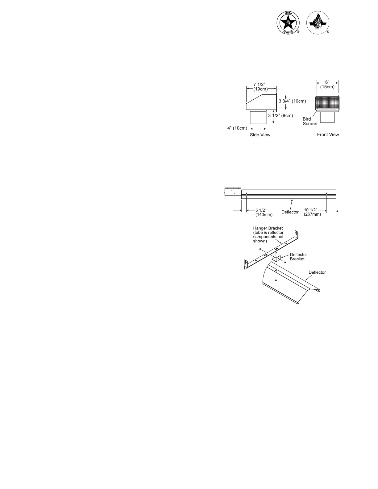
A. Exhaust Hood Package, Part #42924000
Contains:
Exhaust Hood Assembly, #42925540…...................… QTY–1
#8-18 x 1/2 Self-Drilling Screws, #02189030…........… QTY–2
B. Deector Kit, Part #43504010
The Deector Kit is available for use to reduce the
clearances to combustibles below the heater.
Refer to the “Minimum Clearances to Combustibles Table”
in Section 2 when using this Deector Kit. Heater must be
mounted ONLY in the horizontal position when using
this kit.
STERLING “RSG” SERIES
INFRARED RADIANT TUBE HEATER
7
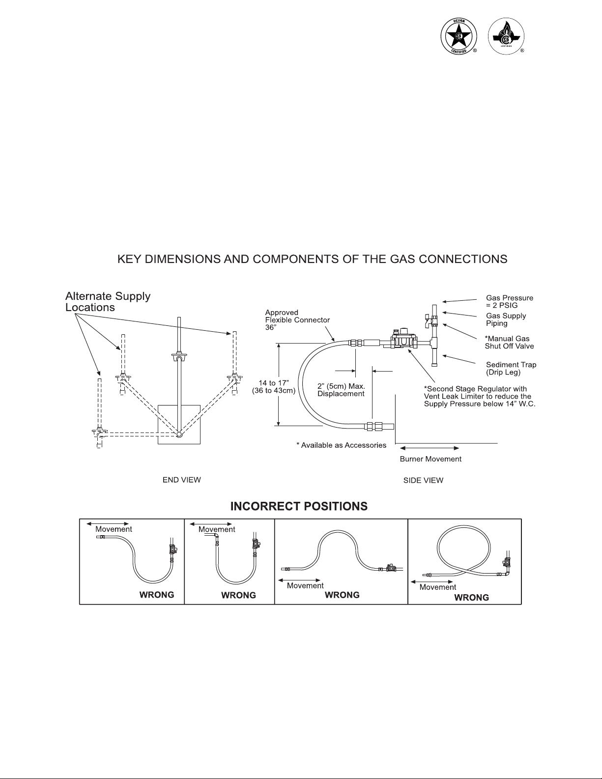
6)GAS CONNECTIONS AND REGULATIONS
US ONLY: A gas connector certied for use on a
tubular type infrared heater per the standard for
Connectors for Gas Appliances, ANSI Z21.24/CSA
6.10 is supplied for installation in US only. The gas
connector is 36" long and 1/2" nominal ID, and
must be installed as shown above, in one plane,
and without sharp bends, kinks or twists.
CANADA ONLY: A Type I hose connector should
be used that is certied as being in compliance
with the Standard for Elastomeric Composite Hose
and Hose Couplings for Conducting Propane and
Natural Gas (CAN/CGA 8.1) and is of length of
36+/- 6 in (90+/- 15 cm). The gas connector must
be installed as shown above, in one plane, and
without sharp bends, kinks or twists.
STERLING “RSG” SERIES
INFRARED RADIANT TUBE HEATER

8
7)GAS PRESSURE TABLE
SUPPLY PRESSURE
GAS TYPE MANIFOLD PRESSURE Minimum* Maximum
Natural Gas 3.5" W.C. 5" W.C. 14" W.C.
Propane Gas 10.0" W.C. 11" W.C. 14" W.C.
*Minimum permissible gas supply pressure for purpose of input adjustment.
This appliance is equipped with a step-opening, combination gas valve. The maximum supply pressure to the
appliance is 14" W.C. or 1/2 P.S.I. If the line pressure is more than the maximum supply pressure, then a second
stage regulator which corresponds to the supply pressure must be used.
STERLING “RSG” SERIES
INFRARED RADIANT TUBE HEATER
9
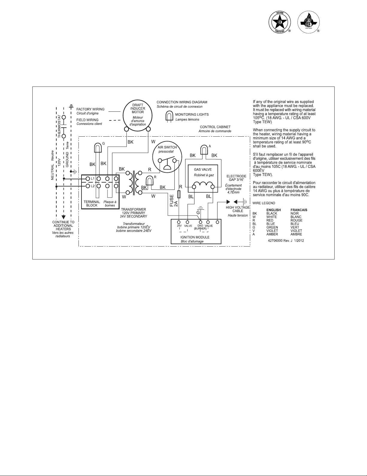
8)ELECTRICAL CONNECTIONS
INTERNAL CONNECTION WIRING DIAGRAM — Direct Spark Ignition
STERLING “RSG” SERIES
INFRARED RADIANT TUBE HEATER
10
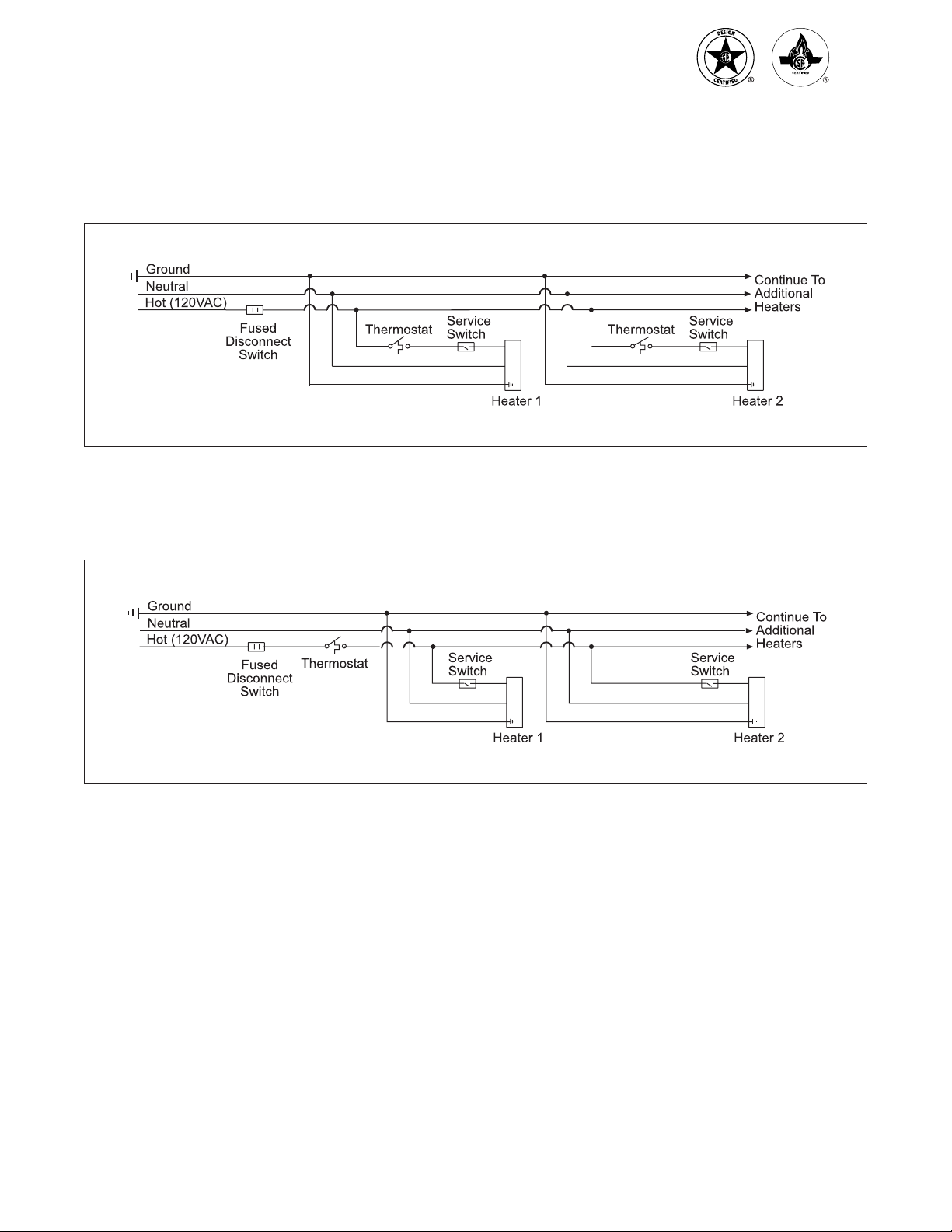
9)THERMOSTAT CONNECTION WIRING DIAGRAMS
B. LINE VOLTAGE (120V) THERMOSTAT CONNECTIONS – MULTIPLE HEATERS PER THERMOSTAT
A. LINE VOLTAGE (120V) THERMOSTAT CONNECTIONS – SINGLE HEATER PER THERMOSTAT
STERLING “RSG” SERIES
INFRARED RADIANT TUBE HEATER

11
C. LOW VOLTAGE (24V) THERMOSTAT CONNECTIONS – SINGLE HEATER PER THERMOSTAT
Order 24V Relay Kit (Part No. 43274020) for Low Voltage (24V) thermostat connection.
D. LOW VOLTAGE (24V) THERMOSTAT CONNECTIONS – MULTIPLE HEATERS PER THERMOSTAT
NOTES:
a. If any of the original wire as supplied with the appliance must be replaced, it must be replaced with
wiring material having a temperature rating of at least 105°C. (18 Ga. CSA 600V Type TEW)
b. When connecting the supply circuit to the heater, wiring material having a minimum size of 14 AWG
and a temperature rating of at least 90°C shall be used.
c. A replaceable 2-amp fuse (1-1/4" long) is located inside the control box.
STERLING “RSG” SERIES
INFRARED RADIANT TUBE HEATER
12
10)VENTING
A. BASIC FLUE VENTING — Venting must comply
with the latest edition of the National Fuel Gas Code
(ANSI Z223.1-latest edition) or the authority having
jurisdiction. Other venting references are in the
equipment volume of the ASHRAE Handbook.
Model
Heat Exchanger
Length ft
Maximum Vent Length ft.
(4" Diameter) Maximum Fresh Air
Intake Length ft
(4" Diameter)
Vertical Venting Sidewall Venting
RSG 25 15 100 75 50
RSG 35 15 100 75 50
RSG 45 15 100 75 50
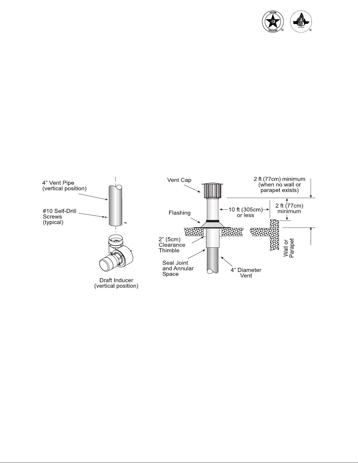
SINGLE HEATER VENTING
(VERTICAL THROUGH THE ROOF)
Note: For residential applications, the heater must
not be connected to a separate chimney, but must
be installed using the venting system specied
below.
1. When venting the heater to outside of building
through a roof, use single-wall metal pipe. This
is to be constructed of galvanized sheet metal or
other approved noncombustible corrosion-resistant
material as allowed by state or local codes.
2. A vent passing through a combustible roof shall
extend through an approved clearance roof thimble.
Double-wall, Type B vent must be used for the
portion of the vent system which passes through
the combustible roof. An approved vent cap must
be attached to end of the ue.
3. The maximum equivalent length of vent pipe should
be carefully observed. A safety switch in the heater
is designed to shut the heater off before excessive
ue restriction causes bad combustion. Refer to the
Vent Sizing Table for maximum vent lengths and
vent pipe diameter.
• Minimum Equivalent Length = 5 ft. of pipe
• Maximum Equivalent Length = 75 ft. of pipe
Use the following correction factors to obtain the
equivalent length:
• Subtract 15 ft. if the run is horizontal.
• Subtract 10 ft. for an approved vent cap.
• Subtract 10 ft. for each elbow beyond 15 ft.
from the heater.
• Subtract 15 ft. for each elbow within 15 ft.
of the heater.
4. Joints between sections of piping shall be fastened
by sheet metal screws or other approved means
and should be sealed to prevent leakage of ue
gas into building. For Residential Installations:
The seams along the length of the piping and the
joints between sections of piping should be sealed
to prevent a potential leakage of ue gas into
building. Use 100% RTV Silicone Rubber Adhesive
sealant suitable for 500°F. For Commercial and
Industrial Installations: Use aluminum or Teon
tape suitable for 550°F (3M Company tapes 433 or
363) or RTV silicone sealant.
5. Avoid locating elbows in the rst 5' of vent pipe
whenever possible. Limit to (2) 90° elbows.
When vent pipe is in a horizontal run, it must
have 1/4 inch per foot rise.
6. All portions of the vent pipe shall be supported to
prevent from sagging (6' spacing is recommended).
STERLING “RSG” SERIES
INFRARED RADIANT TUBE HEATER
13
7. When the vent pipe passes through areas where
the ambient temperature is likely to induce
condensation of the ue gases, the vent pipe
should be insulated and a condensation drain
should be provided.
8. Minimum clearance for single-wall ue pipe to
combustible material shall be 6 inches. This may
be reduced when the combustible material is
protected as specied in the National Fuel Gas
Code or the authority having jurisdiction.
9. Single-wall metal pipe shall not originate in any
unoccupied attic or concealed space and shall not
pass through any attic, inside wall or concealed
space, or through any oor. For the installation
of a single-wall metal pipe through an exterior
combustible wall, refer to latest edition of the
National Fuel Gas Code or the authority having
jurisdiction.
10. A venting system shall terminate at least 3 ft.
above any forced air inlet located within 10 ft.
STERLING “RSG” SERIES
INFRARED RADIANT TUBE HEATER
14
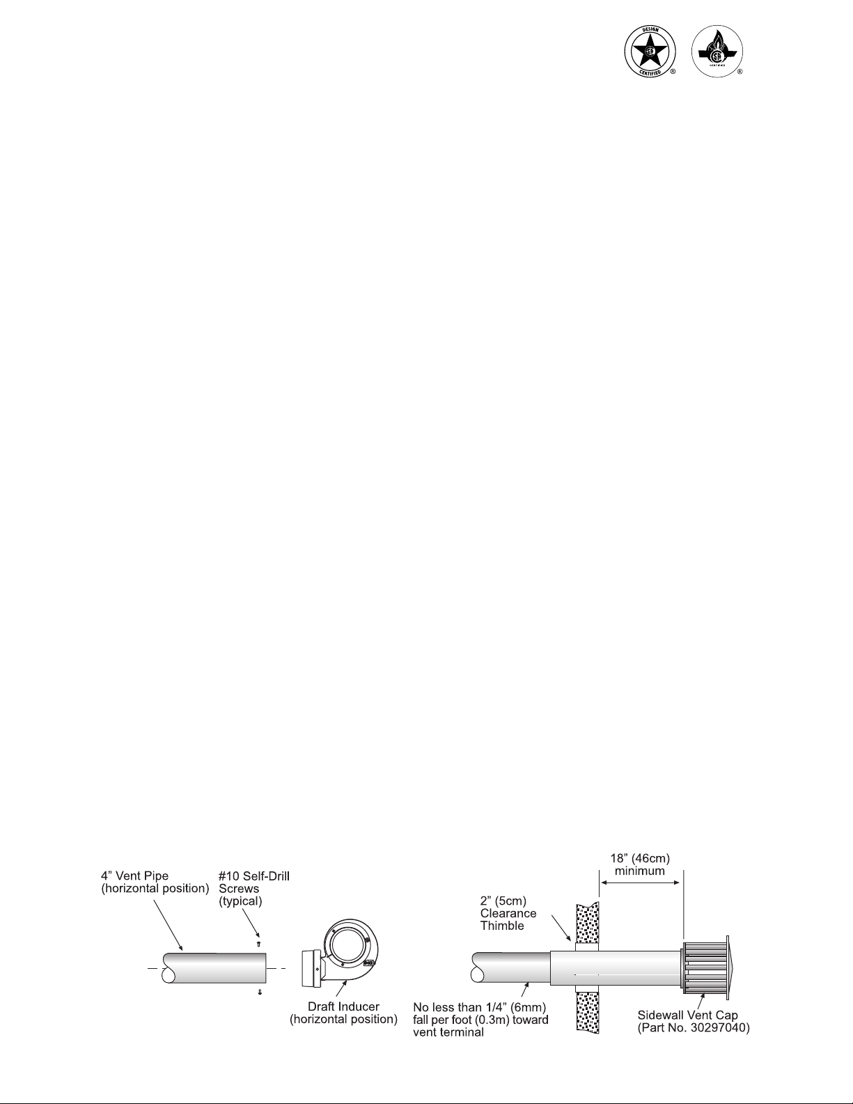
SINGLE HEATER VENTING
(HORIZONTAL THROUGH SIDEWALL)
This heater, when horizontally vented, must be installed
with the approved venting system. When venting the
heater horizontally through a combustible outside
sidewall, the same requirements listed previously
for venting Vertical Through The Roof apply except
as follows:
1. For horizontal venting, the vent lengths may
be as follows:
• Minimum Equivalent Length = 5 ft. of pipe
• Maximum Equivalent Length = 75 ft. of pipe
Use the following correction factors to obtain the
equivalent length:
• Subtract 15 ft. if the run is horizontal.
• Subtract 10 ft. for an approved vent cap.
• Subtract 10 ft. for each elbow beyond 15 ft.
from the heater.
• Subtract 15 ft. for each elbow within 15 ft.
of the heater.
NOTE: To minimize problems associated with
condensation in long horizontal runs, vent pipe
can be insulated.
2. The horizontal venting system approved with this
heater consists of the following components: one
4" Vent Cap (Part #30297040, one 4" x 36" ‘B’ Vent
Section (Part #30496360), and one 4" Wall Thimble
(Part #30500040). Please specify the appropriate
number of 24-inch sections of single-wall vent
pipe and elbows when ordering: Vent Pipe (Part
#30497240), 90° Elbows (Part #30498040), and
45° Elbows (Part #30499040).
3. Avoid locating elbows in the rst 5 feet of vent
pipe whenever possible. Limit the quantity of 90°
elbows to two (2). When vent pipe is in a horizontal
run, it must be pitched downward 1/4 inch per foot
towards the vent terminal. The heater must be
installed level.
4. A minimum clearance of 18 inches must be
maintained between the outside wall and vent
cap (18" clearance will provide stability under
high wind conditions).
5. The horizontal venting system shall not terminate:
• Less than 4 ft. (1.2m) below, 4 ft. (1.2m)
horizontally from or 1 ft. (30cm) above any
door, operable window or gravity air inlet into
any building. The bottom of the vent terminal
shall be located at least 7 ft. (2.1m) above grade
or above snow accumulation level as determined
by local codes.
• Less than 3 ft. (0.9m) from a combustion air inlet.
• Less than 3 ft. (0.9m) from any other building
opening or any gas service regulator.
• Less than 7 ft. (2.1m) above public walkways.
• Directly over areas where condensate or vapor
could create a nuisance or hazard or be harmful
to the operation of gas utility meters, regulators,
relief valves, or other equipment. Building
materials should be protected from ue gases
and condensate.
• Less than 12 inches (0.30m) when directly below
a combustible overhang.
6. In regions of the country where prevailing winds
are consistently higher than 40 mph, it may be
necessary to terminate the vent system above
the roof level.
STERLING “RSG” SERIES
INFRARED RADIANT TUBE HEATER
15
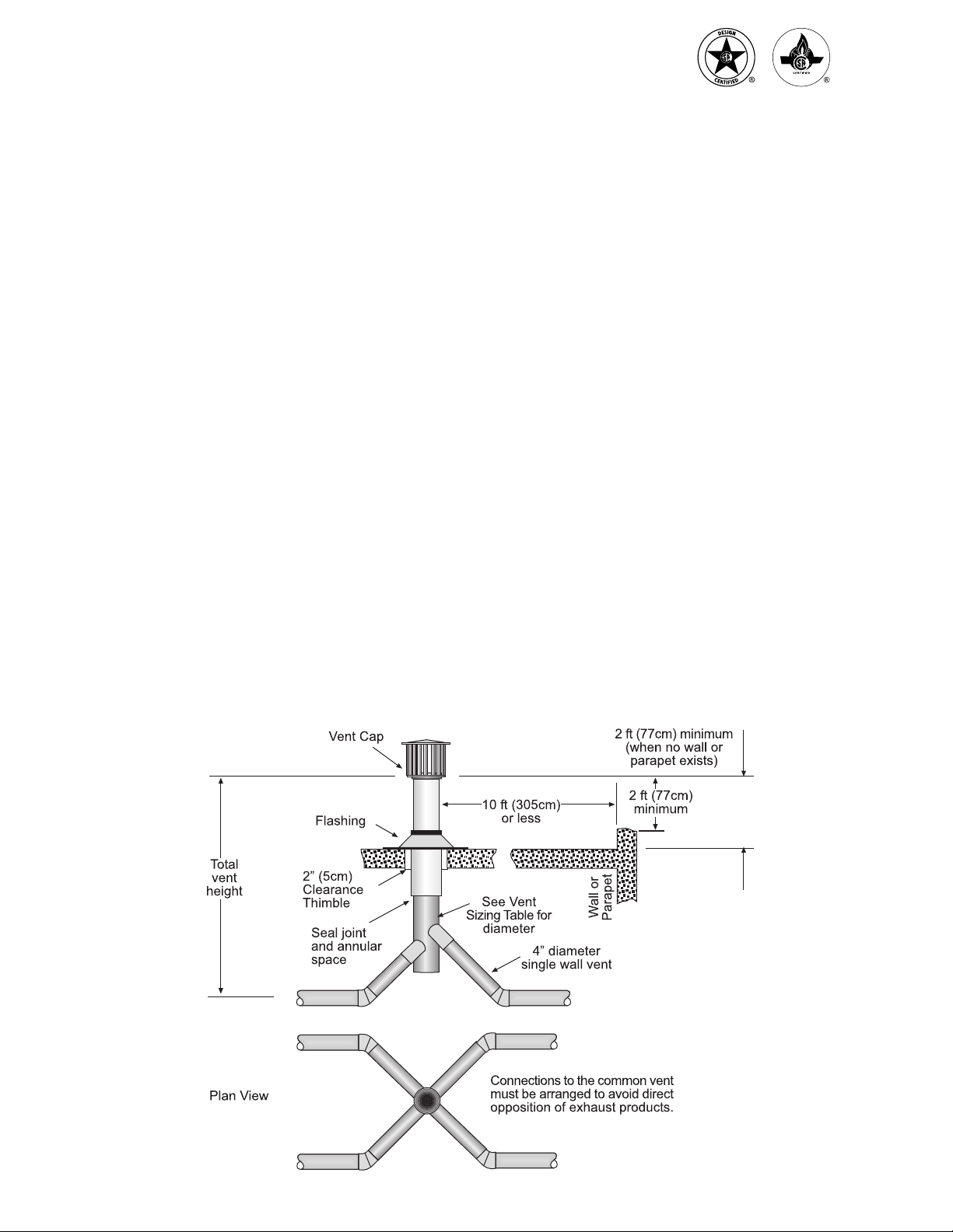
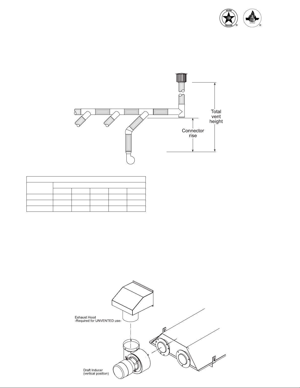
MULTIPLE HEATER VENTING (CONNECTIONS
INTO A COMMON VENT OR MANIFOLD)
Requirements for venting of multiple heaters are the
same as described for “SINGLE HEATER VENTING”
except as follows:
1. The common vent size and total vent height is
normally determined by the number of heaters per
common vent, length of horizontal connector runs,
and connector rise. Connector lengths should be
as short as possible and have a minimum 1/4 inch
per foot rise. Without regard to connector rise and
total vent height due to many possible venting
congurations, the following should be observed:
a) Common vent pipe & vent connector diameter
should be no less than that shown in the
following Vent Sizing Table.
b) The connector length should be no more than
75% of the vertical portion of vent above the
connector.
c) Where possible, use a Y-connector to the
common vent.
2. Material for connectors should be constructed
of galvanized sheet metal or other approved
noncombustible corrosion resistant material as
allowed by state or local codes. All common vent
pipe should be insulated ue pipe or double-wall,
Type B vent.
3. Avoid unnecessary bends. Limit to two (2)
90° elbows.
4. The entire length of vent connector shall be
readily accessible for inspection, cleaning and
replacement.
5. Groups of heaters with a common vent must be
controlled by a common thermostat.
Multiple Heater Vertical Venting Arrangement
STERLING “RSG” SERIES
INFRARED RADIANT TUBE HEATER
16
Multiple Heater Venting (Connections into a Manifold)
VENT SIZING TABLE — Multiple Heater Venting
Number of Heaters
12345
RSG 25 4" 4" 4" 5" 5"
RSG 35 4" 4" 5" 5" 6"
RSG 45 4" 4" 5" 5" 6"
Common Vent Diameter (If a size is not available use the next larger size.)
B. INDIRECT VENTING (UNVENTED HEATERS) —
COMMERCIAL AND INDUSTRIAL INSTALLATIONS
ONLY — This heater requires ventilation in the building
to dilute the products of combustion and provide fresh
air for efcient combustion. Where unvented heaters
are used, gravity or mechanical means shall be
provided to supply and exhaust at least 4 CFM per
1,000 Btu/hr input of installed heaters. Exhaust vents
must be located at the highest point above and in the
vicinity of the heaters, and the inlet vents must be
located below the level of the heaters. An exhaust
hood (Part #42924000) must be placed on the outlet
collar of the draft inducer or on the existing 4" starting
collar when used unvented and must be mounted only
in an upright position and directed towards the reector
body as shown.
The above illustrations and Table of Vent Sizes
for Common Venting of Multiple Heaters are in
accordance with the National Fuel Gas Code
ANSI Z223.1-latest edition, NFPA 54-latest edition,
Equipment Volume of 1988ASHRAE handbook,
current CAN/CGA-B149.1/2-M86 Installation
Code, and AGA publication no. 10M5.85 2.5-2
on Fundamentals of Gas Appliance Venting and
Ventilation-revised but are not a part of the CSA
certication.
STERLING “RSG” SERIES
INFRARED RADIANT TUBE HEATER
17
11)AIR FOR COMBUSTION
If indoor combustion air is to be supplied for a tightly
enclosed area, one square inch of free area opening
shall be provided below the heater for each 1,000 Btu/hr
per hour of heater input. When outside air is used, the
opening below the heater shall be one square inch of
free area for each 4,000 Btu/hr of heater input.
In contaminated atmospheres or high humidity areas,
optional outside air for combustion is recommended.
Adequate clearances around the perforated fresh air
plate must be maintained at all times. In larger open
areas of buildings, inltration normally is adequate to
provide air for combustion.
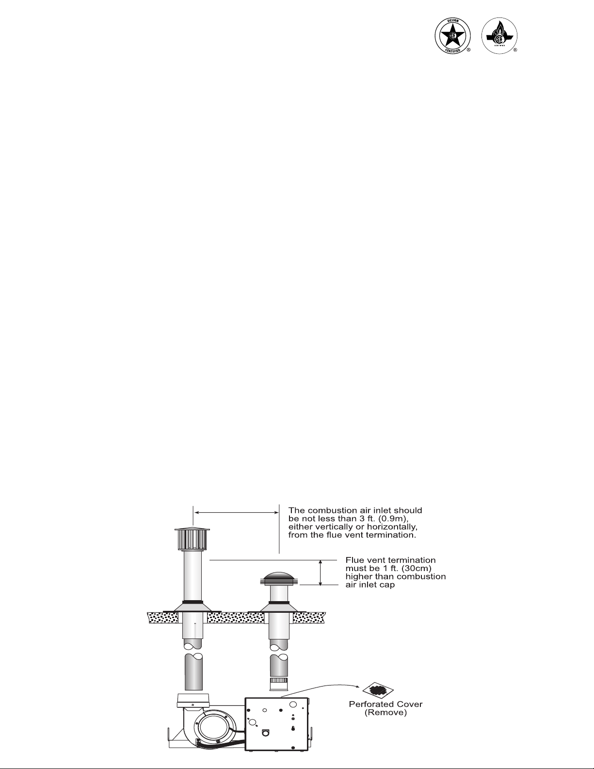
12)DIRECT OUTSIDE AIR FOR COMBUSTION
Outside combustion air should be supplied directly to
the heater when the building is subject to negative
pressure, or when contaminants or high humidity are
present in the building air. These contaminants include
paints, solvents, corrosive vapors or any other foreign
particles that may cause damage to the heater or result
in poor combustion.
Outside combustion air can be brought directly to the
heater by a 4" diameter duct less than 50 ft. long or
equivalent (see table in Section 10 based on selected
model and heat exchanger lengths). This is attached
to the 4" diameter starting collar. The starting collar is
tted to the top of the control box cabinet after rst
removing and discarding the perforated cover. An
approved vent cap must be placed directly on the
end of the outside combustion air inlet pipe.
The combustion air inlet should be not less than
3 ft. (0.9m), either vertically or horizontally, from
the ue vent termination. The air intake terminal
must be located not less than 1 ft. (30cm) above
grade. It is good installation practice to supply
combustion air from the same pressure zone as
the vent outlet. Avoid bringing combustion air to
the heater from an attic space. There is no guarantee
that adequate combustion air will be supplied.
In colder climates, where necessary, insulate the
outside combustion air duct. Avoid locating the outside
combustion air duct directly above the control box.
Provide a capped cleanout T as necessary. In high
humidity applications, the control box should be sealed
with silicone sealer.
In multiple heater applications, the combustion air
intake may be ducted individually or common ducted in
the same conguration as shown for venting in Section
10. For combustion air intake duct sizing, please refer to
the Vent Sizing Table and use the diameter indicated,
based on the number of heaters per duct.
STERLING “RSG” SERIES
INFRARED RADIANT TUBE HEATER

18
STERLING “RSG” SERIES
INFRARED RADIANT TUBE HEATER

19
13)SEQUENCE OF OPERATION
The chart below shows the sequence of operation for the normal operating cycle.
If the ame is not sensed during sequence T3 then the burner will automatically begin ignition sequence T2.
If the ame is not re-established the heater will go to lockout.
STERLING “RSG” SERIES
INFRARED RADIANT TUBE HEATER

Warranty
INFRARED HEATER
260 North Elm St., Westeld, MA 01085
(413) 564-5540 Fax: (413) 562-5311
www.sterlinghvac.com
Sterling (“the Manufacturer”) warrants to the original owner at the original installation site that the Sterling Model
Infrared Heater will be free from defects in material and workmanship for one (1) year from the date of shipment
from the factory. If upon examination by the Manufacturer the Product is shown to have a defect in material or
workmanship during the warranty period, the Manufacturer will repair or replace, at its option, that part of the
product which is shown to be defective.
Extended warranty:
In addition to the warranty stated above the following models will have:
• RSG – Tubes shall be free from defects in material and workmanship for ve (5) years from the date of
shipment from the factory. Burner Head shall be free from defects in material and workmanship for ten (10)
years from the date of shipment from the factory.
This limited warranty does not apply:
a) If the Product has been subjected to misuse or neglect, has been accidentally or intentionally damaged, has not
been installed, maintained or operated in accordance with the furnished written instructions, or has been altered
or modied in any way by an unauthorized person.
b) To any expenses, including labor or material, incurred during removal or reinstallation of the Product.
c) To any damage due to corrosion by chemicals, including halogenated hydrocarbons, precipitated in the air.
d) To any workmanship of the installer of the Product.
This limited warranty is conditional upon:
a) Advising the installing contractor, who will in turn notify the distributor or manufacturer.
b) Shipment to the Manufacturer of that part of the Product thought to be defective. Goods can only be returned
with prior written approval of the Manufacturer. All returns must be freight prepaid.
c) Determination in the reasonable opinion of the Manufacturer that there exists a defect in material or workmanship.
Repair or replacement of any part under this Limited Warranty shall not extend the duration of the warranty with
respect to such repaired or replaced part beyond the stated warranty period.
THIS LIMITED WARRANTY IS IN LIEU OF ALL OTHER WARRANTIES, EITHER EXPRESS OR IMPLIED,
AND ALL SUCH OTHER WARRANTIES, INCLUDING WITHOUT LIMITATION IMPLIED WARRANTIES OF
MERCHANTABILITY OR FITNESS FOR A PARTICULAR PURPOSE, ARE HEREBY DISCLAIMED AND
EXCLUDED FROM THIS LIMITED WARRANTY. IN NO EVENT SHALL THE MANUFACTURER BE LIABLE
IN ANY WAY FOR ANY CONSEQUENTIAL, SPECIAL, OR INCIDENTAL DAMAGES OF ANY NATURE
WHATSOEVER, OR FOR ANY AMOUNTS IN EXCESS OF THE SELLING PRICE OF THE PRODUCT OR ANY
PARTS THEREOF FOUND TO DE DEFECTIVE. THIS LIMITED WARRANTY GIVES THE ORIGINAL OWNER
OF THE PRODUCT SPECIFIC LEGAL RIGHTS. YOU MAY ALSO HAVE OTHER RIGHTS WHICH MAY VARY
BY EACH JURISDICTION.
This manual suits for next models
3
Table of contents
Other Sterling Heater manuals


Popular Heater manuals by other brands


EUROM
EUROM ALUTHERM BASEBOARD Wi-Fi instruction manual

Heatilator
Heatilator GBI25 Series Installation & operating instructions

GILMAN
GILMAN Gemini GCH18B manual

EDM Product
EDM Product 07181 instruction manual

Prem-I-Air
Prem-I-Air N10T24 instruction manual

Soleus Air
Soleus Air HC1-15-12 operating instructions


