11
INSTALLATION - VENTING
COMBUSTION AIR VENTING AND PIPING
Never operate unit heaters without
combustion air and flue gas piping in place or
severe personal injury or death may occur!
CARBON MONOXIDE!
Your venting system must not be blocked by any
snow, snow drifts, or any foreign matter. Inspect
your venting system to ensure adequate ventilation
exists at all times! Failure to heed these warnings
could result in Carbon Monoxide Poisoning
(symptoms include grogginess, lethargy,
inappropriate tiredness, or flu-like symptoms).
1. The combustion air system installation must be in
accordance with the current edition of the National
Fuel Gas Code-NFPA 54 or ANSI Z223.1 National
Fuel Gas Code. In Canada, installation must be in
accordance with CAN/CGA-B149.1 “Installation Code
for Natural Gas Burning Appliances and Equipment”
and CAN/CGA-B149.2 “Installation Code for Propane
Burning Appliances and Equipment”.
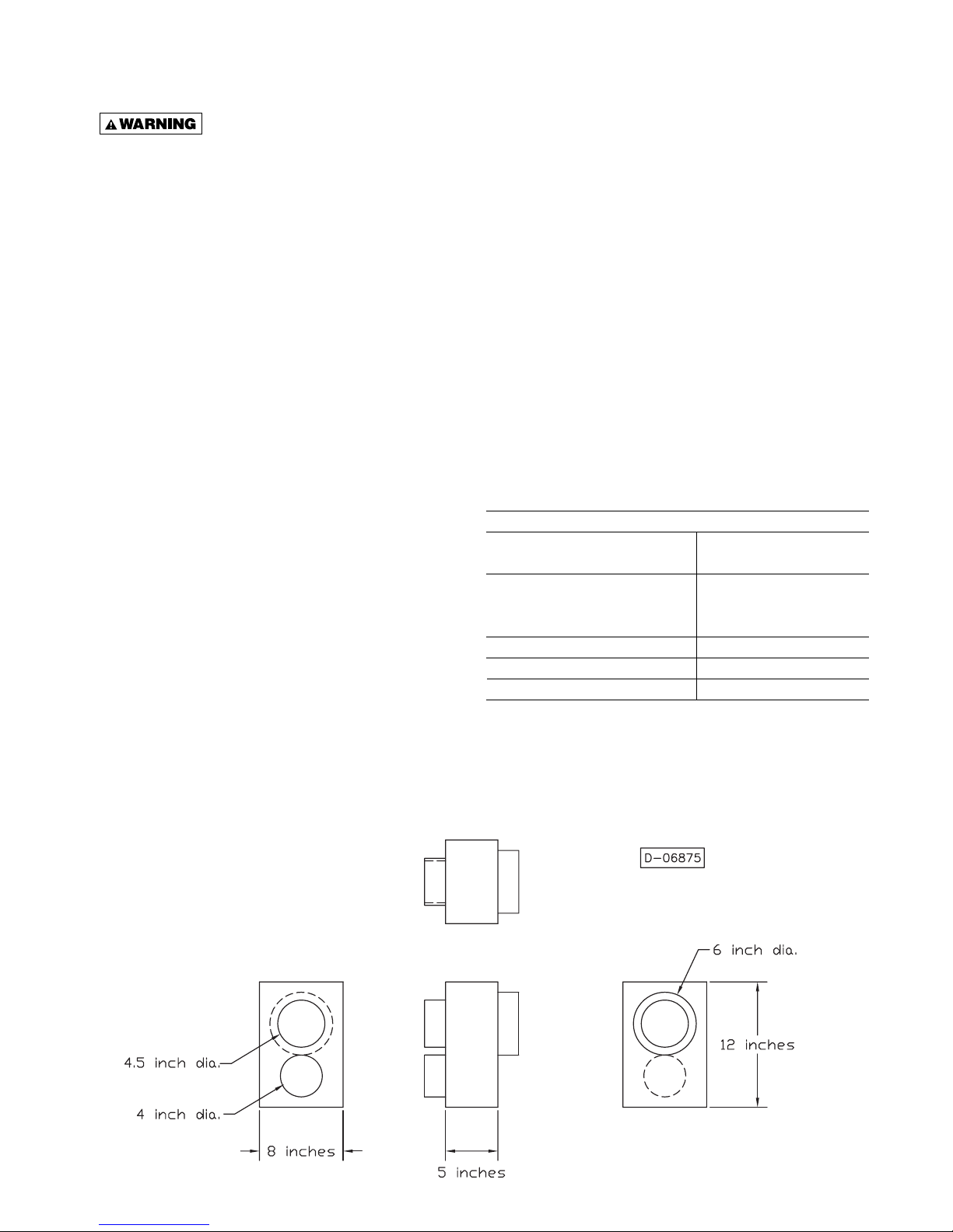
2. The concentric vent box, inlet air screen, deflector
disk, and vent terminal provided with the unit heater
must be installed at the termination point of the
combustion air/vent system. See Figures 6, 7, 8,
and 9 and Table 3.
3. Each unit heater MUST have its own combustion
air system. It MUST NOT be connected to other air
intake systems.
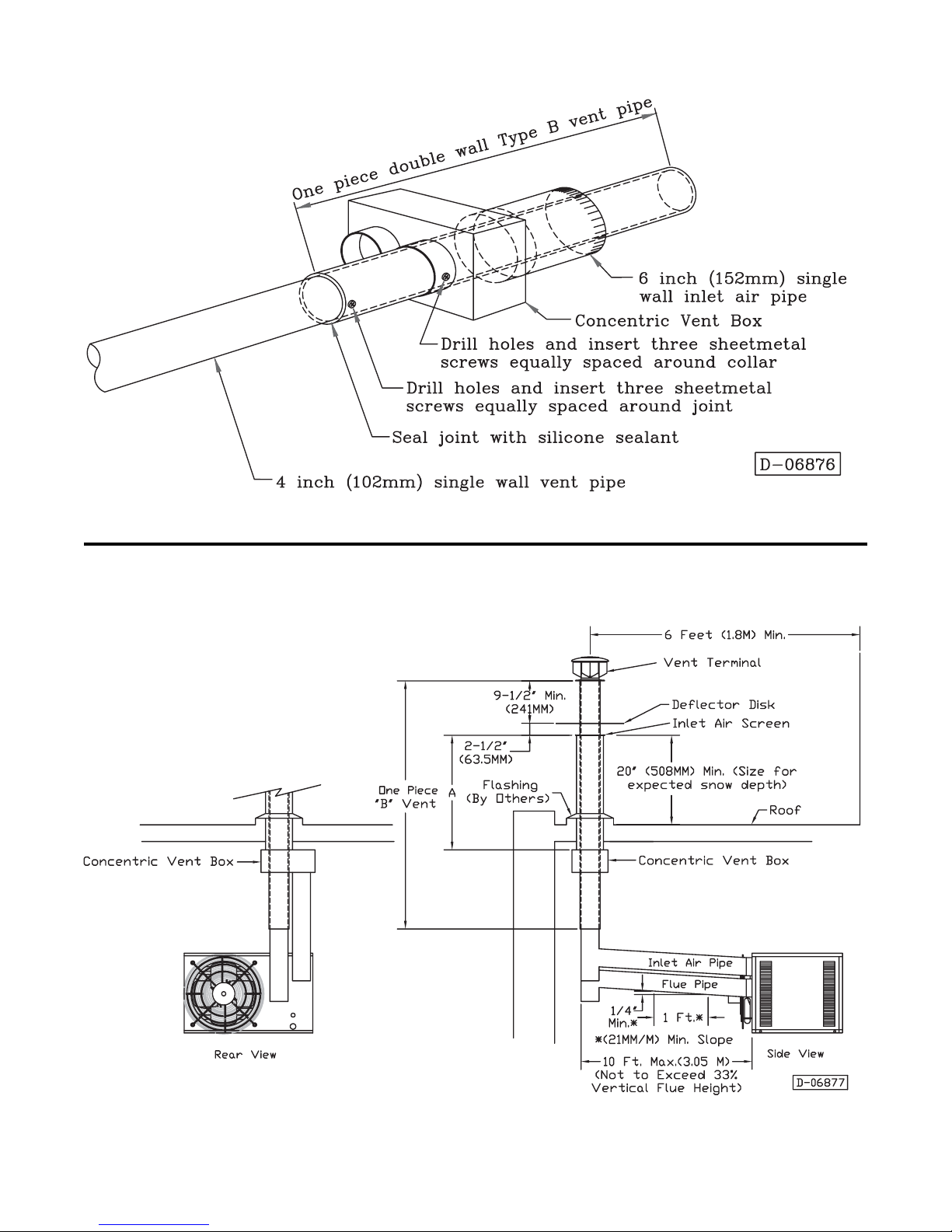
4. Use single wall pipe constructed of 26 GA
galvanized steel or a material of equivalent durability
and corrosion resistance for the vent system. For
installations in Canada, use pipe constructed from
.025 inch thick aluminum or .018 inch thickness
stainless steel. For residential installations in the
United States, vent pipe approved for Category III
appliances must be used between the appliance and
the concentric vent box unless 33% of the vent run is
vertical, then single wall galvanized vent pipe or
double wall Type B vent pipe may be used between
the appliance and the concentric vent box. A single
length of double wall Type B vent pipe must be used
to go through the concentric vent box and outside
wall to the vent terminal.
Never use pipe other than 4 inch
diameter. Never use PVC, ABS or any other non-
metallic pipe for venting! To do so may result
in serious damage to the unit and or severe
personal injury or death!
5. Long runs of single wall combustion air piping
passing through an unheated space may require
insulating if condensation becomes noticeable.
6. The combustion air system must be installed to
prevent collection of condensate. Pitch horizontal
pipes downward 1/4 inch per foot toward the inlet
cap to facilitate drainage. Vertical combustion air
pipes should be piped as depicted in Figure 7.
7. The equivalent length of the combustion air system
must not be less than 5 feet (1.5m) and must not
exceed 40 feet (12m). Equivalent length equals the
total length of straight pipe plus 5 feet (1.5m) for each
90° elbow and 2.5 feet (0.76m) for each 45° elbow.
NOTICE: For optimum performance keep the
combustion air system as straight as possible.
8. Each slip joint must be secured with at least three
corrosion resistant screws. Two full turns of 3M #425
Aluminum Foil Tape or its equivalent must then be
used to seal each joint. General Electric RTV-108,
Dow-Corning RTV-732 or an equivalent silicone
sealant with a temperature rating of 500°F may be
used instead of the tape.
9. For horizontal combustion air systems longer than 5
feet (1.5m), the system must be supported from
overhead building structures at 4 foot (1.2m) intervals
in the U.S. and at 3 foot (0.91m) intervals in Canada.
EXHAUST VENTING
NOTICE: Every unit to be installed MUST use the
Factory supplied Concentric Vent Kit. A Concentric
Vent Kit is shipped with every unit. If you do not
have this kit, contact the manufacturer ASAP to
obtain one prior to installation.
Never operate unit heaters with-
out combustion air and flue gas piping in place or
severe personal injury or death may occur!
1.
Vent system installation must be in accordance with
the current National Fuel Gas Code-NFPA 54 or ANSI
Z223.1 National Fuel Gas Code. In Canada installation
must be in accordance with CAN/CGA-B149.1
“Installation Code for Natural Gas Burning Appliances
and Equipment” and CAN/CGA-B149.2. “Installation
Code for Propane Burning Appliances and Equipment”.
2. The Concentric Vent Kit (which includes a
concentric vent box, air inlet screen, deflector
collar and vent terminal) provided with the heater
by the manufacturer MUST be installed at the
termination point of the combustion air/
vent
system. See Figures 6, 7, 8, and 9 and Table 3.
3. Each unit heater MUST have it’s own vent system.
It MUST NOT be connected to other vent systems
or to a chimney.
4.
Use single wall pipe constructed of 26 GA galvanized
steel or a material of equivalent durability and corrosion
resistance for the vent system. For installations in
Canada, use pipe constructed from .025 inch thick
aluminum or .018 inch thick stainless steel. For
residential installations in the United States, vent pipe
approved for Category III appliances must be used
between the appliance and the concentric vent box
unless 33% of the vent run is vertical, then single wall
galvanized vent pipe or double wall Type B vent pipe
may be used between the appliance and the concentric
vent box. A single length of double wall Type B vent
pipe must be used to go through the concentric vent
box and outside wall to the vent terminal.