Sterling SHR150 User manual
ZP-MEC3-BX-01A
SHR 150/200 Manual
RD: MAY, 2004
RL:1
KH
Owner’s Manual
●INSTALLATION GUIDE
●OPERATION
●MAINTENANCE
●REPLACEMENT PARTS
●WARRANTY
GAS-FIRED INFRA-RED
HEATER
MODELS:
SHR150/200
Caution: Read all instructions before use.
Retain them for future reference. All appli-
ances should be installed by a professional
gas heating equipment service person.
WARNING
Improper installation, adjustment, altera-
tion, service or maintenance can cause
property damage, injury or death. Read
the instructions thoroughly before install-
ing or servicing this equipment.
FOR YOUR SAFETY
DO NOT store or use gasoline or other flam-
mable vapors and liquids in the vicinity of
this or any other heating equipment.
WHAT TO DO IF YOU SMELL GAS:
●DO NOT try to light any gas appliance.
●DO NOT touch any electrical switch: DO
NOT use any phone in your building.
●Immediately call your gas supplier from a
neighbor’s phone. Follow the gas supplier’s
instructions.
●If you cannot reach your gas supplier, call
the fire department.

ZP-MEC3-BX-01A
SHR 150/200 Manual
RD: MAY, 2004
RL:1
KH
TABLE OF CONTENTS
Warnings 1
Ratings 2
Unpacking 2
Heater Installation 3
Choosing Heater Location 4
Minimum Clearance 4
General Mounting Instruction 6
Angle Mounting 7
Ventilation Requirements 7
Piping 7
Testing for Leaks 8
Manifold Pressure Checking 8
Spark Ignition System 9
Service Person’s Trouble Shooting Guide 10
Replacement Parts
Diagram 11
List 12
Main Burner Orifice 13
Procedure for Service warranty Claim 14
Customer’s record 14
Warranty Back Cover
WARNING
DO NOT Install or service this heater yourself. Call a
Professional gas heater equipment service person.
●DO NOT place flammable material on or
near the heater.
●When used with a thermostat, heater may
start at any time.
●Use only in well ventilated areas. DO NOT
install in an area where the heater could be
isolated.
●DO NOT obstruct the flow of combustion
and ventilation air.
●The installation must conform with local
codes or, in the absence of local codes, with
the National Fuel Gas Code, ANSI Z221.1*
in U.S.A. or in Canada CAN 1.2.16M81.
●DO NOT hang the heater with chains in
applications where repetitive swinging
motion of the heater may fatique the gas
connections to the heater or damage the
heater. Failure to do so could cause
property damage, bodily injury or death.
Rigid mounting should be used in the above
application.
●DO NOT hang heater on gas lines, water
lines conduit, etc. Hang only on structural
member (s) which could sufficiently support
the heater without impairing or endangering
other functions of the structural member (s).
●If heater is installed at altitudes 2,000 feet
or more above sea level the orifice must be
changed according to the chart on page 13.
●DO NOT use this heater if any part has
been under water. Immediately call a
professional gas heating equipment service
person to inspect the heater and to replace
any part which has been under water.
●Any changes to this heater or its controls
can be dangerous. Any additions, changes
or conversions required in order for this
heater to satisfactory meet the application
needs must be made by a profesiional gas
heating equipment service person using
factory specified and approved parts.
●Any safety screen, guard or part removed
for installation or service must be replaced
prior to operating the heater to avoid
property damage, bodily injury or death.
*ANSI Z223.1 (latest edition) is available from American Gas
Association, 8501 East Pleasant Valley Rd., Cleveland OH
44131 (216-524-4990), and all NFPA codes are available
from National Fire Prevention Association, Batterymarch Park
Quincy, MA 02269 (617-770-3000) or check your local library.
1
Model Type
Designation
Rate
Designation
Gas
Designation
SHR 150,000 – BTUH
200,000 – BTUH
N – Natural
L – Liquid
Petroleum/
Propane
ALTITUDE ORIFICE CHANGES
When the heater is installed at altitudes exceed-
ing 2,000 feel above sea level, the input must be
reduced by 4 percent for each 1,000 feet above
sea level.
Example: SHR150 installed at 4,000 feet
altitude;
Normal Input Rate 150,000 BTUH
Less 16% for 4,000 feet
above sea level 24,000 BTUH
Reduced input for 4,000
feet altitude 126,000 BTUH
For correct size orifice, refer to altitude orifice
conversion chart on page 13. Please call your
local heating parts supplier and/or gas company
for orifices in your area.
IMPORTANT
WARNING
Do Not alter the installed orifice in any manner.
Improper alteration could result in Carbon
Monoxide poisoning and possible death. If the
orifice must be changed or cleaned contact a
professional gas heating equipment service
person.
CHECKING FOR DAMAGE OR SHORTAGES
1. Unpack the heater from its carton and
examine the contents for damage or missing
parts.
2. If any parts are damaged at the time of deliv-
ery, notification should be made on the Bill of
Lading from the transportation
company.
3. Concealed damage must be filed within
fifteen (15) days with the carrier.
4. Claims for shortage must be filed with the
distributor within five (5) days.
2
RATINGS

ZP-MEC3-BX-01A
SHR 150/200 Manual
RD: MAY, 2004
RL:1
KH
VALVE ASSEMBLY
FIGURE 1
1. Remove valve and heater from carton.
Remove the three screws from each venturi
collector bell located on one end of the
heater.
2. Slide valve onto collector bells and insert
two vertical screws. Then install remaining
four screws.
3. To avoid possible damage to wiring connec-
tion, it may be advantageous to hang heater
before connecting wires. Connect two gray
wires to the flame sensors located by the
electrodes. Connect the two spark-plug
type high tension leads to the Electronic
Ignition Control. If a thermostat is used,
separate the two red wires that are twisted
together and connect the thermostat
between them. If a thermostat is not used,
connect the red wires to the positive side
of the power source and the single blue
wire to the negative via a switch.
HEATER INSTALLATION
Installation of Sterling Gas Fired Infra-Red
Heaters should conform to all Sterling Heating
Installation Design Procedures including ventila-
tion. All local and national codes requirements,
or in the absence of local codes, the National
Electrical Code (NFPA No. 70) and the National
Fuel Gas Code (ANSI A223.1 – latest edition)
in the U.S.A. or in Canada CSA B149.1-00 shall
be followed. ANSI Z223.1, is available from
the International Gas Association 8501 East
Pleasant Valley Road, Cleveland OH 44131,
and all NFPA codes are available from National
Fire Prevention Association, Batterymarch Park,
Quincy, NA 02269.
3
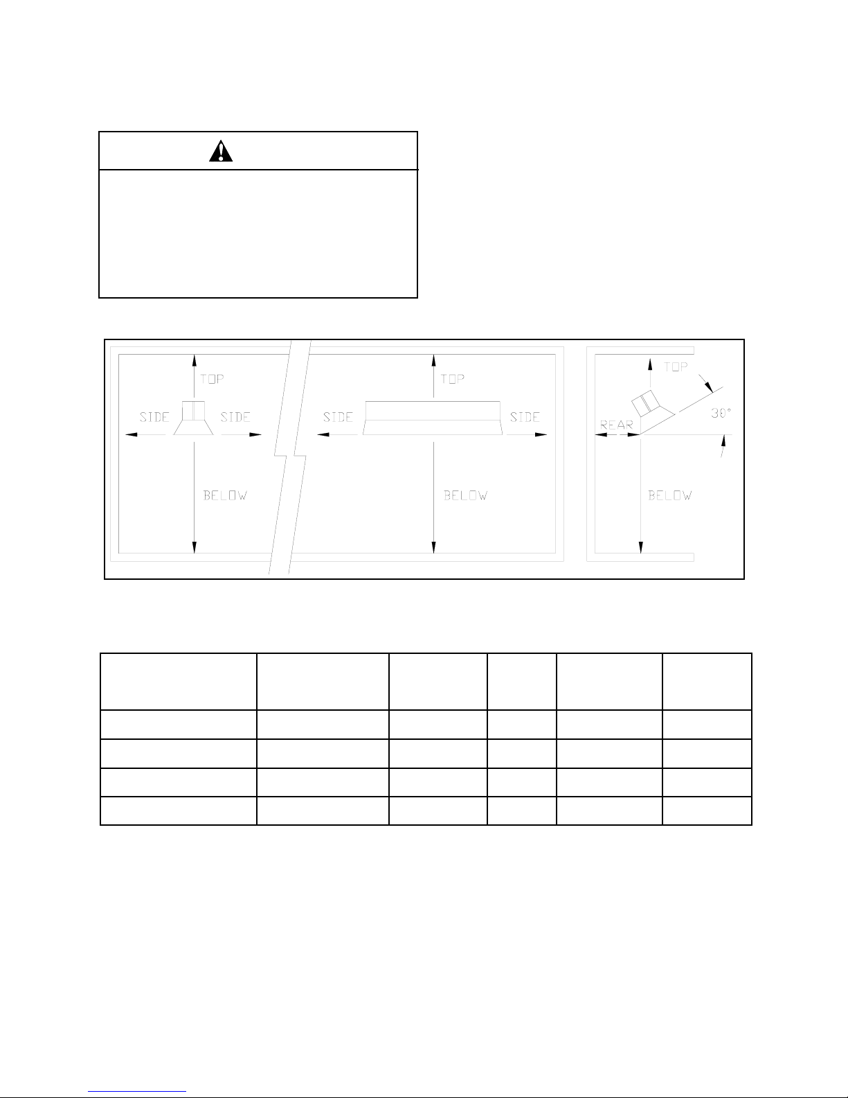
CHOOSING HEATER LOCATION
This model heater must be mounted with mini-
mum clearances between the heater and sur-
rounding combustible surfaces a shown in Table
A, below.
It should also be located with respect to building
construction and equipment in a manner which
provides sufficient clearance and accessibility for
servicing and cleaning of the burner and controls.
WARNING
Be aware of good safety practices by wearing
personal protective equipment such as gloves
and safety glasses to avoid being injured by
sharp metal edges in or around the heater and
while cutting or drilling holes. Failure to follow
these warnings could cause bodily injury or
death.
MINIMUM CLEARANCE TO COMBUSTIBLE MATERIAL
FIGURE 2
CLEARANCE TO COMBUSTIBLES CHART
MODEL NO. MOUNTING
ANGLE
FRONT SIDE
(Shade
to wall)
REAR
(Shade
to wall)
TOP
(Bottom of shade
to ceiling)
BELOW
(Tile to Floor)
SHR150L/N Horizontal ° Angle 55 55 52 121
SHR150L/N 30° Angle 80 36 52 121
SHR200L/N Horizontal ° Angle 55 55 52 121
SHR200L/N 30° Angle 80 36 52 121
4
TABLE A

ZP-MEC3-BX-01A
SHR 150/200 Manual
RD: MAY, 2004
RL:1
KH
5
IMPORTANT: In certain installations, clearances
in Table A & Figure 1 may not be adequate to
keep temperatures below 160°F. In these instal-
lations, it is the installer’s responsibility to insure
that single or multi-heater placement be such that
continuous operation of the heater or heaters will
not cause combustible materials or materials in
storage to attain a temperature of excess of 160°
F.
NOTE: When heaters are installed in proximity to
temperature-sensitive material (for example, vinyl
faced insulation), it is the installer’s responsibility
to insure that the surface temperature does not
exceed the allowable temperature of that mate-
rial. In these installations, minimum clearances
noted in Table A on page 4 are to be increased
by the necessary amount.
Under no circumstances should this heater be
installed in a combustible atmosphere or in a
location where the heater controls can be subject
to ambient temperatures in excess of 150°F.
INSTALLATION IN AIRCRAFT HANGARS
This heater is suitable for use in aircraft hangars
when installed in accordance with the following
standard: NFPA No. 409 (latest edition).
1. A clearance of 10 feet must be maintained
from the bottom of the heater to the highest
surface of the largest aircraft to be housed
in the hangar.
2. A minimum clearance of 8 feet must be
maintained from the bottom of the heater in
other sections of the aircraft hangars, such
as offices and shops.
3. The heater must be located so that it will be
protected from damage by aircraft and other
objects, such as cranes and movable scaf
folding.
4. The heater must be installed where it will be
accessible for serving and adjustment.
INSTALLATION IN COMMERCIAL GARAGES
This heater is suitable for use in commercial
garages when installed in accordance with ANSI/
NFPA No. 88B 1985 (latest edition), which states
clearances to combustible construction or
material in storage, from heater and vent, must
conform to standard NFPA No. 54 (ANSI Z223.1
latest edition), in U.S.A. and in Canada CSA
B149.1-00.
American National Standard Institute (ANSI)
Z223.1 (latest edition) states “overhead heaters
shall be installed at least (8) feet above the floor.”
In addition, they shall be located high enough to
maintain the minimum distance to combustibles,
as shown on the heater rating plate, between the
heater and any vehicles parked below the heater.
INSTALLATION OTHER THAN SPACE HEATING
Use for processing applications voids the
warranty and C.S.A. certification. Any additional
changes, or conversions required in order for the
heater to satisfactorily meet the heater needs
must be made by a Sterling distributor, or other
qualified agency, using factory specified and ap-
proved parts.
HEATER INSTALLATION CON’T

6
GENERAL MOUNTING INSTRUCTIONS
The following instructions are a guide to general
installation only. The procedure for installing the
infra-red system is based on structural members
of the building and how they can be used to
support the heating system. Before proceeding
with the installation of the system, we suggest
that you consult your Sterling Distributor for the
proper procedure for your particular job.
Since most installations will differ in many
details, these instructions are general. Sound
judgment must be exercised and careful supervi-
sion is essential to assure the installation will be
made in the best manner possible for trouble-free
operation and at minimal cost.
All systems must be done in accordance with
acceptable practices, local codes, and applicable
standards.
This heater is suitable for reflector mounting
angles up to 30 degrees along the short axis.
Improper angle mounting can result in overheat-
ing of controls and combustible materials.
The hangers support the infra-red heater and the
reflectors.
Chain, with a working load of at least 200 lbs., is
recommended for hanging the heater by connect-
ing the hanger(s) to a beam or other support.
If rigid means such as rods are used in place of
chains, swing joints or other means of sufficient
length must be provided to compensate for
expansion.
IMPORTANT: For either horizontal or angle
mounting, the long axis of the heater must be
level. Use only non-combustible mounting
hardware.
NOTE: It is the responsibility of the installer to
insure that the chosen suspension system will
support at least 200 lbs.
MODEL
AVERAGE MOUNT-
ING HEIGHT (IN
FEET)
DISTANCE FROM WALL
TO REAR OF HEATER
(LONG AXIS
PARALLEL TO WALL)
DISTANCE
BETWEEN
HEATERS
(SHORT
AXIS ) FT.
30°
ANGLE
HORI-
ZONTAL
30°
ANGLE
HORI-
ZONTAL
SHR150L 26 32
SERVICE
CLEAR-
ANCE
32 22-40 130
SHR150N 26 32 32 22-40 130
SHR200L 28 34 34 22-40 130
SHR200N 28 34 34 22-40 130
MAX. DISTANCE
BETWEEN ROWS
OR MAX. BUILD-
ING WIDTH (FT.)
FIGURE 2

ZP-MEC3-BX-01A
SHR 150/200 Manual
RD: MAY, 2004
RL:1
KH
ANGLE MOUNTING
This heater is suitable for mounting angles with the short
axis rotated in either direction as shown in Figure 3.
Improper angle mounting can result in damage to the
heater or unsafe operation.
IMPORTANT: For either horizontal or angle mounting,
the long axis of the heater must be level. Use only non-
combustible mounting hardware. In general, mounting
angles above 25° are only used for special application of
spot and area heating.
7
VENTILATION REQUIREMENTS
Natural or mechanical means shall be provided to
exhaust at least 4 CFM per 1,000 BTU per hour
input on installed heaters on Natural gas, 4.5
CFM per 1,000 BTU per hour input on installed
heaters on LP gas. Exhaust openings for remov
ing flue products shall be above the level of the
heaters.
When buildings are so tight that normal
infiltration does not provide the necessary air for
combustion, outside air must be introduced.
IMPORTANT: PIPING PRACTICES
1. Installation of ground pipe joint union is
required at the gas inlet connection to the
control valve on the heater. All components
upstream of the control valve are field sup
plied by the installer. See Figure 4.
2. If permitted by code, an approved 18” or 24”
flexible connection between the heater and
piping is recommended.
3. Installation of a 6” gas line trap “Drip-Leg” is
required at the inlet connection to the
heater. Failure to provide a drip leg could
result in condensation and foreign matter in
the valve which could cause damage.
4. On propane-fired heaters, a main line filter
is recommended.
5. Installation of a manual shut off valve is
required. Provide a 1/8 inch N.P.T. plugged
tap, accessible for test gauge connection,
immediately upstream of the gas supply
connection to the heater. It may be part of
the shut off valve as shown in Figure 4.
6. Piping joint compounds must be resistant to
the action of liquefied petroleum gases.
7. All piping must be installed according to
local codes.
8. To insure proper performance and full input
capacity, the gas supply line leading to the
heater from the main supply should be of an
adequate size. Check your local plumbing
codes for correct sizing for your installation.
FIGURE 3
FIGURE 4

TESTING FOR LEAKS
WARNING
All gas piping and connections must be tested for
leaks after the installation is completed.
DO NOT use a match or open flame of any kind to
test for leaks. Never operate the heater with leaky
connections.
Failure to follow these warnings could result in prop-
erty damage, bodily injury or death.
1. Disconnect the heater and the manual shut off
valve from the gas supply piping system during
any pressure testing .
2. Isolate the heater from the gas supply piping
system by closing the manual shut off valve
during any pressures equal to or less than 1.2
psig.
3. For Steps 4 and 5, apply a soap solution
to all connections and joints. If bubbles
appear, leaks have been detected and
should be corrected.
4. The supply system should be checked
first with the heater gas valve turned
OFF.
5. After the supply is checked, turn the
heater gas valve ON and check the
heater piping and controls while unit is in
operation.
6. The opening between the pipe and the
wall, or floor, through which the gas
piping is inserted should be sealed by
caulking.
MANIFOLD PRESSURE CHECKING
Be sure to check the manifold pressure with a
water manometer to verify proper operation of the
heater.
A pressure regulator is an integral part of the
automatic valve on all models for both Natural
and LP Gas. This pressure regulator will com-
pensate for minor fluctuations in input pressure,
but is NOT a suitable substitute for the line pres-
sure regulator on a Natural or LP gas line.
1. The manifold pressure can be meas-
ured at the 1/8 inch pipe tap on the
control valve. Pressure measurements
should be taken with a water mano-
meter. (Gauges which measure in
ounces per square inch or pounds per
square inch are not accurate enough to
properly measure or set the pressure).
MANIFOLD PRESSURE
(Inches Water Column)
Natural 5.0
Propane/LP 10.0
2. The line pressure can be measured at
the 1/8 inch pipe tap in the main gas
line. Pressure measurements should
be taken with a water manometer.
LINE PRESSURE
(Inches Water Column)
Min. Max.
Natural 6.0 14.0
Propane/LP 11.0 14.0
Input rate should never exceed that shown on the
rating plate. Orifice changes must be made by a
professional gas heating equipment service per-
son.
Natural Gas models are orificed for 1000 BTU/
CU FT gas. Propane/LP Gas models are orificed
for 2500 BTU/CU FT gas. When the actual heat-
ing value differs, an orifice change may be re-
quired.
IMPORTANT
IMPORTANT
CAUTION
CAUTION
8
ZP-MEC3-BX-01A
SHR 150/200 Manual
RD: MAY, 2004
RL:1
KH
9
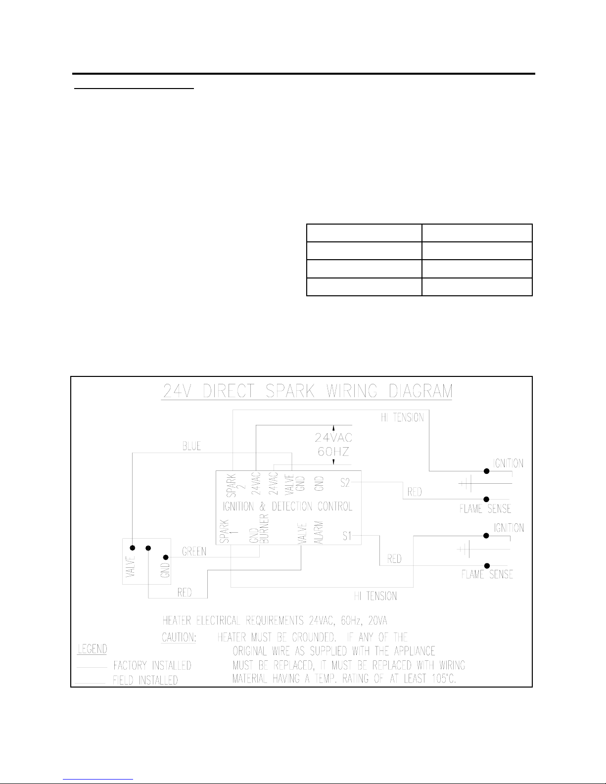
SPARK IGNITION SYSTEM INFORMATION
Sequence of Operation:
1. Supplies power to the electronic pulse-
generator circuit for the spark igniter.
2. Allows up to 21.6 seconds (maximum) for ig-
nition and 1 try before system safety lockout
occurs.
3. Senses burners flame for safe lighting.
4. Shuts off spark after burners are lit.
The control is powered by a 24 VAC transformer
and activated when the temperature control
requests for heat.
When the control is activated by the temperature
control’s request for heat, control performs a
safe-start check that determines proper operation
of the control before beginning the normal se-
quence of operation. Once the Safe Start Check
operation passes, the control turns on the spark
circuit and at the same time, the control opens
the gas control’s main valves, which allows gas to
flow to the main burners.
LED STATUS
OFF IDLE
BLINKING NORMAL
STEADY ON LOCKOUT
WIRING DIAGRAM

10
TROUBLE SHOOTING GUIDE
SERVICE HINTS AND MAINTENANCE CAUSE AND CORRECTIONS
TURN THERMOSTAT TO CALL FOR HEAT
24 VOLTS AT CONTROL TRANSFORMER
24 VOLT AT CONTROL
24 VOLTS OUT CONTROL
24 VOLTS AT GAS CONTROL
SPARK ACROSS IGNITER
OR IGNITER/SENSOR GAP
MAKE SURE THE MANUAL
LEVER ON THE VALVES
ARE OPEN AND THAT
THERE IS GAS GOING TO
THE VALVES.
MAIN BURNERS LIGHT
SPARKS STOPS
WHEN BURNERS
ARE LIT.
SYSTEM RUNS UNTIL
CALL FOR HEAT ENDS
CHECK FOR LINE VOLTAGE POWER SUPPLY
CHECK 24V WIRING FROM IGNITION CON-
TROL TO GAS VALVE
PULL IGNITION LEAD AND CHECK SPARK AT
IGNITION STUD.
CAUTION: HIGH VOLTAGE
SPARK OKAY??
CHECK 24V WIRING FROM TRANSFORMER
TO IGNITION CONTROL
REPLACE CONTROL
REPLACE TRANSFORMER
CHECK IGNITION CABLE, GROUND WIRE, CERAMIC INSULA-
TOR AND CAP, AND CORRECT. CHECK BOOT OF THE IGNI-
TION CABLE FOR SIGNS OF MELTING OR BUCKLING. TAKE
PROTECTIVE ACTION TO SHIELD CABLE & BOOT FROM EX-
CESSIVE TEMPERATURES.
CHECK FOR 24 VAC ACROSS VALVES AND VALVES TERMI-
NALS ON CONTROL IF NO VOLTAGE, REPLACE CONTROL.
SPARK IGNITERS MAY BE OUT OF POSITION. CHECK ELEC-
TRICAL CONNECTIONS BETWEEN CONTROL & GAS VALVES IF
OKAY, REPLACE GAS VALVES OPERATOR.
YES NO
YES
NO
YES
YES
YES
YES
NO
YES
NO
NO
NO
NO
NOTE: IF CONTROL GOES INTO LOCKOUT, RESET SYSTEM BY
INTERRUPTING POWER SOURCE.
CHECK CONTINUITY OR SENSOR CABLE AND GROUND WIRE.
CHECK THAT BURNER FLAME COVERS ALL ELECTRODES.
CHECK GROUND CONTINUITY. IF CHECKS ARE OKAY, RE-
PLACE CONTROL MODULE.
NOTE: IF CONTROL GOES INTO LOCKOUT, RESET SYSTEM BY
INTERRUPTING POWER SOURCE.
CHECK CONTINUITY OR SENSOR CABLE AND GROUND WIRE.
NOTE: IF GROUND IS POOR OR ERRATIC, SHUTDOWN MAY
OCCUR OCCASIONALLY EVEN THOUGH OPERATIONS IS NOR-
MAL AT THE TIME OF CHECKOUT.
IF CHECKS ARE OKAY, REPLACE CONTROL MODULE.
YES
YES
NO
YES
NO
CHECK FOR PROPER TEMPERATURE CONTROLLER OPERA-
TION. REMOVE VALVE LEAD AT CONTROL IF VALVE CLOSES,
RECHECK TEMPERATURE CONTROLLER AND WIRING; IF NOT,
REPLACE GAS VALVE OPERATOR.
CALL FOR HEAT ENDS;
SYSTEM SHUTS OFF
YES
TROUBLE SHOOTING ENDS
YES
NO
REPEAT PROCEDURE UNTIL TROUBLE FREE OPERATIONS IS OBTAINED.
ZP-MEC3-BX-01A
SHR 150/200 Manual
RD: MAY, 2004
RL:1
KH
11
MAINTENANCE
The efficiency of the heater can be impaired if it
gets dirty. If the heaters are installed in areas
where considerable dust is present in the air,
periodic burner cleaning may be necessary. Dust
may be entrained in the primary air supply and
deposited on the back side of the ceramic. This
can be very easily removed by dusting the
ceramic face and the air inlet with a blast of low
pressure air, a maximum of 20 psi. Occasionally
pilots or the burners refuse to function properly
after a summer shutdown. The burner passage-
ways can be cleaned out by using a flexible brush
(bottle brush) It is common for spider webs or
cocoons to be found present in these areas.)
Preventative maintenance is the best policy.
Heaters should be cleaned once a heating
season
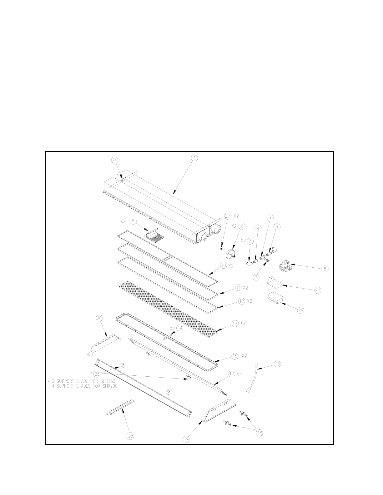
REPLACEMENT PARTS DIAGRAM– Reference next page
REPLACEMENT PARTS LIST Series Reference Page 11
ITEM
NO.
PART NAME
SHR150L
SHR150N
SHR200L
SHR200N
1 Burner Assy. 53573-1 53573-1 53576-1 53576-1
2 Orifice Support 49950-2 49950-2 49950-2 49950-2
3 Street Elbow 13503-G2 13503-G2 13503-G2 13503-G2
4 Nipple 2” 13504-G3 13504-G3 13504-G3 13504-G3
5 Tee 52629-1 52629-1 52629-1 52619-1
6 Nipple 3” 13504-63 13504-63 13504-63 13504-63
7 Nipple 1 1/2” 13504-G2 13504-G2 13504-G2 13504-G2
8 Valve 52387-2 52387-2 52387-2 52387-2
9 Baffle Assy. 49975-G1-1 49975-G1-1 49982-G1-1 49982-G1-1
10 Gasket (Fiberfraux) 51178-G1 51178-G1 51178-G1 51178-G1
11 Gasket (Fiberfraux) 49448-G1 49448-G1 49448-G1 49448-G1
12 Gasket (Fiberfraux) 49929-G1 49929-G1 49229-G1 49229-G1
13 Ceramic Tile 52138-G2 52138-G2 52138-G2 52138-G2
14 Central Tile Divider 51878-G1 51878-G1 51878-G1 51878-G1
15 Tile Retainer 51295-G2 51295-G2 51295-G2 51295-G2
16 High Tension Lead 51045-6 51045-6 51045-6 51045-6
17 Side Shade 51931-G1 51931-G1 51932-G1 51932-G1
18 Electrode 51487-G1 51487-G1 51487-G1 51487-G1
19 End Shade (Electrode) 51879-3 51879-3 51879-3 51879-3
20 End Shade 51927-2 51927-2 51927-2 51927-2
21 Valve & Control Bracket 53266-1 53266-1 53266-1 53266-1
22 Ignition Control 52960-1 52960-1 52960-1 52960-1
23 Support Shade 50576-G2 50576-G2 50576-G2 50576-G2
24 Connector Bracket 53295-1 53295-1 53295-1 53295-1
25 Shade Brace - - 52625-1 52625-1
26 Cap & Spring Convert 51270-G4 - 51270-G4 -
27 Main Burner Orifice See page 13 for replacement part numbers.
12

ZP-MEC3-BX-01A
SHR 150/200 Manual
RD: MAY, 2004
RL:1
KH
13
ACCESSORY GUIDE
MODEL NO DESCRIPTION ECOSCHWANK36 ECOSCHWANK52
JA276 Transformer X X
ORIFICE REPLACEMENT
MODEL NO NATURAL (N) PROPANE/LIQUID PETROLEUM (LP)
SHR150 46655-G18 (2) (DMS #27) 49955-G5 (2) (DMS #38)
SHR200 49955-40 (2) (DMS #18) 49955-G6 (2) (DMS #32
ALTITUDE ORFICE CONVERSION CHART
MODEL
NO
STAN-
DARD
ORIFICE
(DMS)
FOR USE AT ALTITUDES ABOVE (FEET)
2000 3000 4000 5000 6000 7000 8000
SHR150L #27 #28 #28 #29 #29 #29 #30 #30
PART NO 49955-G18 49955-42 49955-42 49955-G11 49955-G11 49955-G11 49955-G1 49955-G1
SHR150N #38 #39 #40 #41 #41 #42 #42 #43
PART NO 49955-G5 49955-43 49955-44 49955-45 49955-45 49955-G17 49955-G17 49955-G4
SHR200L #18 #19 #19 #20 #21 #22 #23 #24
PART NO 49955-40 49955-G12 49955-G12 49955-G25 49955-46 49955-47 49955-G2 49955-48
SHR200N #32 #33 #34 #35 #35 #36 #36 #37
PART NO 49955-G6 49955-G21 49955-38 49955-49 49955-49 49955-G8 49955-G8 49955-41

14
PROCEDURE FOR SERVICE OR WARRANTY CLAIM
1. Contact the distributor from whom you
purchased the product or a professional gas
heating equipment service person to deter
mine the problem.
2. The Distributor or professional gas heating
equipment service person may replace or
repair the defective part or require that the
part be removed and shipped to the
manufacturer for repair or replacement.
3. All service charges and shipping costs are
the responsibility of the owner.
4. Note to distributors and professional gas
heating equipment service personnel: all
returned parts must be accompanied by a
completed Return Material Tag which is
provided to all distributor.
5. All service and warranty claims must have
the product model and serial number on
the Returned Material Tag.
Under no circumstances should anyone ex-
cept a professional gas heating equipment
service person attempt to remove, repair, or
replace
CUSTOMER’S RECORD
Keep for your records. Record the information concerning your New Sterling Gas-Fired Infra-Red
Heater. The Model Number and Serial Number will be found on the rating plate.
Date of Purchase_______________ Sterling Model No. _________________Serial No.___________
Distributors Name____________________________________________________________________
Address___________________________________________State____________Zip______________
Comments__________________________________________________________________________
__________________________________________________________________________________
ZP-MEC3-BX-01A
SHR 150/200 Manual
RD: MAY, 2004
RL:1
KH
WHAT IS COVERED
Sterling warrants that this product is free from
defects in material or workmanship under normal
use and service subject to the terms of this docu-
ment.
ONE YEAR WARRANTY
Sterling’s sole obligation under this warranty shall
be limited to furnishing replacement parts, for 12
months from date of initial installation of the
heater, but not to exceed 18 months from the
date of shipment by Sterling of the heater, for any
parts which Sterling’s examination shall disclose
to its satisfaction to be defective. Defective parts
are to be returned to Sterling, with transportation
charges prepaid.
ADDITIONAL LIMITED WARRANTY
In addition to the above mentioned First-year
Warranty, Sterling warrants to the original pur-
chaser of a C.S.A. Certified Infra-Red Heater the
following. That at any time during the nine (9)
year period following the expiration of the first-
year Warranty, at the discretion of Sterling will
repair or replace to original or equivalent design,
the Effect-Tile Burner exclusive of control, which
proves to be inoperable due to defects in material
or factory workmanship to the satisfaction of
Sterling. Sterling’s sole obligation under this Ad-
ditional Limited Warranty shall be limited to fur-
nishing Effect Tile Burners only.
WHAT IS NOT COVERED
Sterling will not be responsible for labor charges
for analysis or a defective condition in the heater
or for installation of replacement part. The War-
ranties provided herein will not apply if the input
of the heater exceeds the rated input, as indi-
cated on the name plate, by more than 5%, or if
the heater in the judgment of Sterling has been
subjected to misuse, negligence, accident, con-
taminated and/or corrosive atmospheres, condi
tions which create a contaminated and/or corro
sive atmosphere in the presence of high tem-
perature or open flame, excessive thermal shock,
physical damage, impact, or abrasion, alterna-
tions by unauthorized service, operation contrary
to Sterling’s instructions or if the serial number
has been altered, defaced, or removed. Sterling
shall not be liable for any default or delay in per-
formance by it of these warranties caused by any
contingency beyond its control, including war,
government restrictions or restraints, strikes, fire,
flood, or short or reduced supply of raw material,
or parts. Written permission is required for the
return of any parts of equipment and such return
must be made on the basis of transportation
charges prepaid. Shipments may be refused
unless prior permission is obtained, and returned
prepaid. This Warranty applies only within the 50
United States of America.
LIMITATIONS AND EXCLUSIONS
This document contains all warranties made by
Sterling and may not be varied, altered or ex-
tended by any person. There are no promises,
or agreements extending from Sterling other than
the statements contained herein. THIS WAR-
RANTY IS IN LIEU OF ALL WARRANTIES EX-
PRESS OR IMPLIED, TO THE EXTENT AU-
THORIZED BY THE LAWS OF THE STATE OF
SALE, INCLUDING SPECIFICALLY THE WAR-
RANTIES OF MERCHANTIBILITY OR FITNESS
FOR A PARTICULAR PURPOSE.
It is understood and agreed that Sterling’s
obligation hereunder is limited to repairing or re-
placing parts determined to be defective as
stated above.
In no event shall Sterling be responsible for
any alleged personal injuries or other special inci-
dental or consequential damages.
GAS-FIRED INFRA-RED HEATER LIMITED WARRANTY
Some states do not allow certain warranty exclu-
sions or limitations on how long a warranty lasts
or the exclusions or limitations of incidental or
consequential damages. In such states, the
above limitations or exclusions may not apply to
you and are not intended to do so where prohib-
ited by law. This warranty gives you specific legal
rights. You may also have other rights which vary
from state to state.
STERLING HVAC EQUIPMENT
260 NORTH ELM STREET
WESTFIELD, MA 01085
This manual suits for next models
1
Table of contents
Other Sterling Heater manuals


Popular Heater manuals by other brands


ORIGO
ORIGO FH9401 instruction manual

Caloritech
Caloritech CX Series Installation, operation & maintenance instructions

Modine Manufacturing
Modine Manufacturing HEX5 Series Installation, Parts, Service, and Maintenance Manual

Space-Ray
Space-Ray SSJ30-N2B Installation and operation instructions

Econo Heat
Econo Heat OMNI OWH-500 Installation, operation and service instructions

Zibro
Zibro Kamin R 102 C Operation manual