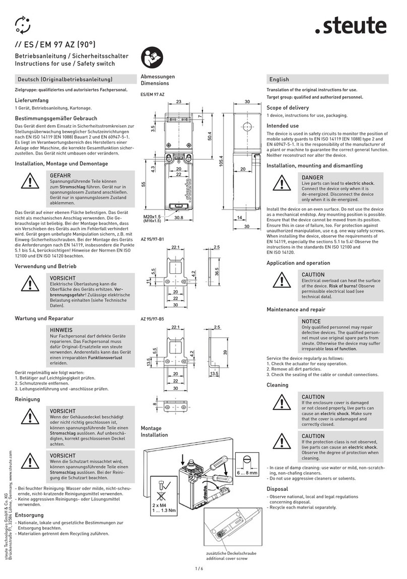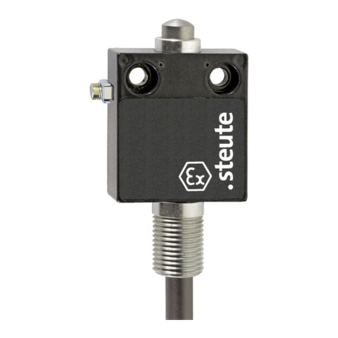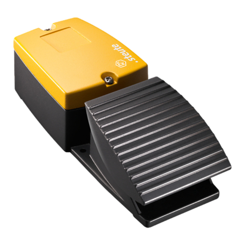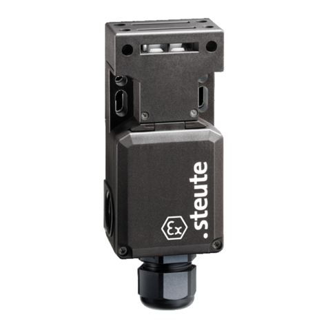
Ex ZS 71 (VD)
steute Technologies GmbH & Co. KG,
Brückenstraße 91, 32584 Löhne, Germany, www.steute.com
3 / 20
Montage- und Anschlussanleitung / Seilzug(-Not)schalter
Mounting and wiring instructions / (Emergency) pull-wire switch
Instructions de montage et de câblage / Arrêt (d’urgence) à câble
Istruzioni di montaggio e collegamento / Interruttore (di emergenza) a fune
Instruções de montagem e instalação / Chave (de emergência) acionada por cabo
Application and operation
- Use device only within the permitted electrical load limits (see
technical data).
- For short-circuit protection, use fuse size 6 A (gG/gN).
- Use device only within the permitted ambient temperature range
(see product label and technical data).
- Include the device in the equipotential bonding (earthing) via the
mounting or bracket or the external earthing connection.
Cleaning
- Use a damp cloth to clean devices in hazardous areas. This prevents
electrostatic charge.
- In case of damp cleaning: Use water or mild, non-scratching,
non-chafing cleaners.
- Do not use aggressive cleaners or solvents.
Service, maintenance, repair
=
DANGER
Live parts. Explosive atmosphere. Electric shock
hazard! Explosion hazard! Risk of burns! Do not
repair defective or damaged devices. Replace them.
Do not rebuild or modify the device in any way.
With careful mounting as described above, only minor maintenance is
necessary. We recommend a routine maintenance as follows:
1. Check pull-wire function.
2. Remove dirt.
3. Check sealing of the cable or conduit connections.
Disposal
- Observe national, local and legal regulations concerning disposal.
- Recycle each material separately.
N.B.
Any mounting position is possible. Furthermore, EN 60079-14 has to
be applied for the installation of electrical equipment in hazardous
areas. Moreover, the ATEX test certificate and the enclosed special
conditions have to be observed. The device has been developed in
order to assume safety functions as a part of an entire plant or ma-
chine. A complete safety system normally covers sensors, monitoring
modules, indicator switches and concepts for safe disconnection. For
the integration of the device in the entire system: strictly observe and
respect the control category determined in the risk assessment.
Therefore, a validation according to EN ISO 13849-2 or EN 62061 is
necessary. Furthermore, the Performance Level according to EN ISO
13849-1 and SIL CL Level according to EN 62061 can be lower than
the single level because of the combination of several safety compo-
nents and other safety-related devices, e.g. by serial connection of
sensors. It is the responsibility of the manufacturer of a plant or ma-
chine to guarantee the correct general function. Subject to technical
modifications.
English
The device complies with the European standards for explosion protec-
tion EN IEC 60079-0, EN 60079-1 and EN 60079-31. It is intended for
use in hazardous areas of zones 1 and 2 as well as zones 21 and 22 ac-
cording to EN 60079-14. Comply with the requirements of EN 60079-
14, e.g. with regard to dust deposits and temperature limits. The de-
vice is used on machines and plants where a command may be given
anywhere along the pull-wire. Emergency pull-wire switches (VD) trig-
ger an emergency-stop command. Pulling or breaking the preten-
sioned wire triggers perform the switching function. In the case of
emergency pull-wire switches (VD), this also causes the contacts to
latch. The reset can only be carried out manually by unlocking with the
push-button. Observe country-specific standards and directives.
Mounting and wiring
Mount the (emergency) pull-wire switches for one-side actuation
Ex ZS 71 … according to the instructions and pretense the wire accord-
ingly (see »Mounting without compensation spring«, »Mounting with
compensation spring«, »Configuration of switch cam«).
To detect correct mounting:
1. Remove enclosure cover.
2. Tense the wire so that the switch cam is in middle position
(position B).
Special conditions and »X« marking
- The device's connection cables must have a fixed installation and be
set up in a manner that protects them from mechanical damages.
- If the connection is carried out within a hazardous area, connect the
cable inside an enclosure which meets the requirements of an ap-
proved ignition protection type to EN IEC 60079-0, Section 1.
Installation, mounting, dismantling
=
DANGER
Live parts and explosive atmosphere. Electric
shock hazard! Explosion hazard! Before commis-
sioning, check device for correct installation. Com-
ply with national regulations.
=
DANGER
Live parts. Explosive atmosphere. Electric shock
hazard! Risk of burns! Connecting and disconnect-
ing only to be performed by qualified and author-
ised personnel. Connecting and disconnecting only
in non-explosive environment.
Before mounting the pull-wire, remove the red PVC sheath from the
pull-wire in the clamping range of the pull-wire (see »Mounting notes
wire thimbles«)! After fitting the wire, pull strongly on it several times,
as the pull-wire and the wire thimble will deform. Subsequently, re-
tense the wire using the DUPLEX wire clamp, eye-bolt or tensioner.
Mount the wire supports every 3 m. Install the wire supports in one
line in order to avoid stronger friction and to secure a proper function
of the tension springs.


