manuals.online logo
Brands
  1. Home
  2. •
  3. Brands
  4. •
  5. Stevens Aero Model
  6. •
  7. Toy
  8. •
  9. Stevens Aero Model QuickOats 250 Manual

Stevens Aero Model QuickOats 250 Manual

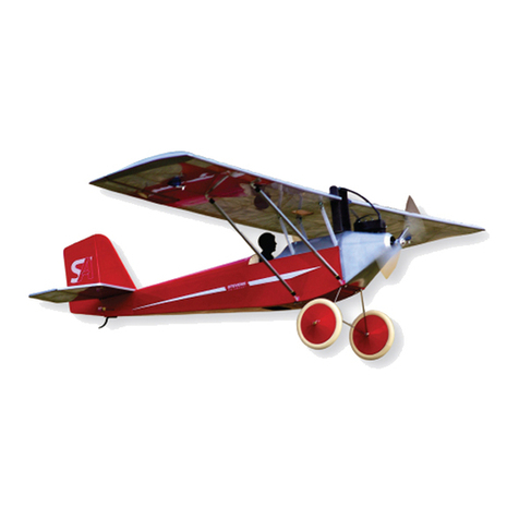
QuickOats 250
Wing Span: 29 inches | Wing Area: 180 inches2| Flying Weight: 5.0-6.0 ounces
Version 1.0
Build Instructions September 13, 2011!
(c) 2011 Stevens AeroModel all rights reserved.!Page 1
WARRANTY
Stevens AeroModel guarantees this kit to be free from defects in both material and workmanship at the
date of purchase. This warranty does not cover any component parts damaged by use or modification.
In no case shall Stevens AeroModel’s liability exceed the original cost of the purchased kit. Further,
Stevens AeroModel reserves the right to change or modify this warranty without notice.
LIABILITY RELEASE
In that Stevens AeroModel has no control over the final assembly or material used for final assembly,
no liability shall be assumed nor accepted for any damage resulting from the use by the user of the
final user-assembled product. By the act of using the user-assembled product, the user accepts all
resulting liability.
If the buyer is not prepared to accept the liability associated with the use of this product, the buyer is
advised to return this kit immediately in new and unused condition to the place of purchase.
THIS PRODUCT IS NOT INTENDED FOR CHILDREN 12 YEARS OF AGE OR YOUNGER
WARNING: This product may contain chemicals known to the State of California to cause cancer and
or birth defects or other reproductive harm.
PRODUCT SUPPORT
This product has been engineered to function properly and perform as advertised with the suggested
power system and supporting electronics as outlined within this product manual. Product support
cannot be provided nor can Stevens AeroModel assist in determining the suitability or use of
electronics, hardware, or power systems not explicitly recommended by Stevens AeroModel.
For product assembly support, replacement parts, hardware, and electronics to complete this model
please contact Stevens AeroModel on-line at www.stevensaero.com.
Stevens AeroModel
PO Box 15347 - Colorado Springs, CO 80935 - USA
719-387-4187 - www.stevensaero.com
Build Instructions September 13, 2011!
(c) 2011 Stevens AeroModel all rights reserved.!Page 2
Project Checklist
Kit Contents
☐Laser Cut Wood (8 Sheets)
☐Build Instructions
☐Computer Drawn Detail Page
☐Pre-Cut Acetate Windscreen
Taped to back of wood brick:
☐1 - 0.045 in. x 12 in. wire [1004]
☐1 - 0.032 in. I.D. x 12 in. length nylon tubing (pushrod housing) [2022]
☐2 - 0.020 in. x 18 in. wire (pushrods) [*]
☐Hardware Bag
1 - Package #64 rubber bands (GW/AP012)
1 - Basswood Laser Cut Elevator Joiner “E5” [*]
1 - 1/8 x 4 in. Dowel [1020]
1 - 1-1/2 in. length 1/16 in. dia. Heat Shrink Tube [2020]
2 - 3/16 in. diameter x 1/16 in. thick Neo-Magnets [4014]
2 - #4 Nylon Washers [3018]
4 - #2 x 1/4 in. screw [3011]
Suggested Electronics and Other Equipment(Available at StevensAero.com)
☐Transmitter with at least 3 channels
☐Micro Receiver with at least 3 channels (4-6g)
☐2 HS-35HB (4.5g ea.) or HS-55 (8.0g ea.) Ultra-Micro Servos
☐SA Sport BL250 2200KV motor (SUPA1510-15)
☐SA Sport 10A ESC (SUP10AESC)
☐GWS 6x3 Propellor (GW/EP6030)
☐Prop adaptor for 2mm shaft (EFLM1920)
☐1 Pair 1-1/2 in. Mini Light Wheels (DUB150MW)
Required Building Supplies and Tools
☐1/4 oz. Thin CA Glue (PAAPT10)
☐1/4 oz. Medium CA Glue (PAAPT04)
☐CA glue applicator tips (PAAPT21)
☐Hobby Knife with ample supply of #11 blades
☐Sanding block with 400 and 600 grit paper
☐Heat Gun and Covering Iron
☐Small Needle Nose Pliers
☐1/2 in. wide clear hinge tape (DUB916)
☐3/4 in. wide self-adhesive Velcro (DUB348)
☐Soldering Iron
Optional Building Supplies and Tools
☐Balsa filler (HCAR3401)
☐CA glue accelerator (PAAPT15)
☐CA glue de-bonder (PAAPT16)
☐CA Glue Thick (PAAPT20)
☐Long sanding bar
☐Masking Tape (Low tack blue painters tape)
☐Modeling Clay for Ballast
Build Instructions September 13, 2011!
(c) 2011 Stevens AeroModel all rights reserved.!Page 3
General Assembly Instructions
Thank you, for purchasing this Stevens QuickOats™(250), inspired by the venerable 1937 Quaker free
flight model line, with a touch of “toon” style. This product has been developed and manufactured using
state of the art CAD/CAM systems and features a unique interlocking construction process that, when
compared to traditional methods found in other model aircraft kits, save countless hours of measuring,
cutting, sanding, and fitting. We are certain that you’ll find our kit to offer a truly exceptional build
experience. As this kit is recommended for the novice model builder and pilot; we invite beginners who
have purchased this kit to seek the help of a seasoned builder and pilot. At any time should one run
across a term or technique that is foreign please don’t hesitate to contact our staff with your questions.
READ THIS!
Please READ and RE-READ these instructions along with any other included documentation prior to
starting your build and/or contacting our staff for builder support.
Pre-sanding
Do not skip this step. Prior to removing any parts from the laser cut sheet wood use a sanding block
loaded with 250-400 grit paper and lightly sand the back side of each sheet of wood. This step removes
any residue produced as a result of the laser cutting process and, as we have found that most stock wood
sizes run several thousandths of an inch over sized, slightly reduces the thickness of each sheet.
Leave your pre-sanded parts in the sheet until required in the assembly process.
Protecting your worktable
Use the poly tube that this kit was shipped in as a non-stick barrier between your worktable and the
product assembly. Promptly clean up any epoxy spills with rubbing alcohol and a disposable towel.
Bonding the assembly
As this product tabs, notches, and otherwise interlocks like a 3D puzzle we suggest that when fitting parts
you dry fit (use no glue) the parts together first. It’s advised to work 1-2 steps ahead in the instructions
using this dry-fit technique which allows ample opportunity to inspect the fit and location of assembled
components and realizes a benefit as each successive part contributes to pulling the entire assembly
square. Once you arrive at the end of a major assembly sequence square your work on top of a flat
building table and revisit the dry fit joints with glue. Using the dry-fit process you’ll be able to recover from
a minor build mistake and will ultimately end up with a more square and true assembly.
Unless otherwise noted in the instructions we find it easier to tack glue part (temporarily bonding parts in
assembly using a small dot of glue) using medium CA glue applied with a fine-tip CA glue applicator tip.
Tight fitting joints should be bonded using thin CA glue applied, sparingly, with a CA glue applicator tip.
Never force the fit!
Remember this is a precision cut kit our machines cut to within 5 thousandth of an inch in accuracy. Yet
the wood stock supplied by the mill may vary in thickness by up to 20 thousandths. This variance in the
wood stock can cause some tabs/notches to fit very tight. With this in mind, consider lightly sanding, or
lightly pinching, a tight fitting tab rather than crushing and forcing your parts together. You’ll break fewer
parts in assembly and will end up with a more square and true airframe.
Manual Updates
Please check our web-site for updates to these instructions prior to commencing the build.
To obtain downloads and updates relative to this model aircraft kit, please visit the corresponding product
page at StevensAero.com
Build Instructions September 13, 2011!
(c) 2011 Stevens AeroModel all rights reserved.!Page 4
Builders Notes
Build Instructions September 13, 2011!
(c) 2011 Stevens AeroModel all rights reserved.!Page 5
Fuselage
Fuselage parts are designated with a “F” followed by a numeric. Parts have been
numbered so that the fuselage assembly and required parts follows in numeric order
from F1 to F20 (F20 used in final assembly step 82).
The fuselage is of traditional sheet side with central crutch assembly. Many of the
formers will need to be installed in a FORWARD and TOP orientation. Unless
otherwise specified by an etched “TOP” or “BOTTOM” designation, formers should be
installed etched part number right side up and facing the FRONT of the assembly.
You will dry fit the majority of this fuselage assembly together only gluing at the final
instructional steps. When parts cannot easily be retained with friction, use a single tiny
drop of medium CA glue applied sparingly through a CA glue applicator tip to “tack glue”
the part in place. Should you commit an error in assembly it will be easier to recover
from the mistake and remove or correct the part fit in error if you do not slather the
assembly in glue after each step! Further, this method of assembly will allow our
interlocking design to do it’s job as each successive part installed within the fuselage
will help pull the entire structure square and true.
1. Fit the balsa instrument panel F2 to the ply central crutch F1, with the
etching facing the REAR of F1 - see picture #1.
2. Fit and tack glue former F3 to the REAR of F1. Ensure that the end marked
“TOP” is positioned up.
3. Assemble the fuselage side F4. Fit and bond F4b to F4a, then fit and bond
the uprights F4c and F4d in place. F4c and F4d have half round tabs that
ensure they can be inserted correctly.
4. Fit the central crutch assembly to the fuselage side F4. Ensure that all tabs
are seated fully, and that all mating surfaces are flush against each other.
Tack glue the assembly if necessary, but do not thoroughly bond.
5. Fit the ply motor mount F5 to the FRONT of F1 and to F4. Ensure that the
end marked “TOP” is up.
6. Fit the landing gear brace F6 to the BOTTOM of F1 and the FORWARD
edge of the slot within fuselage side F4.
7. Coat one side of the ply windscreen frame F7a with thick CA. Carefully
position balsa F7b over F7a, matching INSIDE and OUTSIDE edges, to
create “F7” windscreen frame.
Build Instructions September 13, 2011!
(c) 2011 Stevens AeroModel all rights reserved.!Page 6
☐
☐
☐
☐☐
☐
☐
☐
Build Instructions September 13, 2011!
(c) 2011 Stevens AeroModel all rights reserved.!Page 7
Step 1
F1
F2
F3
F4a
F4b
F1
Step 2
Step 3
Step 3 cont.
Step 4
Step 5
Step 6
Step 7
F4c
F4d
FRONT
REAR
TOP
F4
F5
TOP
F6
F7b
F7a
REAR F4
F1
F1
F4
FRONT
Fuselage Continued
8. Fit the windscreen frame assembly F7 to the fuselage side F4, immediately
above the instrument panel F2.
9. Repeat step #3 to assemble the remaining fuselage side “F8” from parts
F8a, F8b, and F8c.
10. Fit the fuselage side F8 to the fuselage assembly. Ensure all tabs are
seated fully, and that all mating surfaces are flush with each other. Bond all
mating surfaces within the fuselage assembly with CA.
11. Fit and bond nose sheeting F9 to the TOP of the ply motor mount F5, the
fuselage sides, and the windscreen F7.
12. Fit and bond the cabin TOP F10 to the fuselage sides, windscreen, and
former F3.
13. Fit the ply landing gear bracket F11 to the slots in F1 and the fuselage sides.
14. Fit the landing gear brace F12 behind F11, engaging the slots in F1 and the
fuselage sides. Bond the landing gear pocket assembly by wicking thin CA
in and around the assembly. Ensure that you do not fill the pocket with
glue!
15. Fit and bond the lower nose sheeting F13 to the fuselage sides and the
motor mount F5.
Build Instructions September 13, 2011!
(c) 2011 Stevens AeroModel all rights reserved.!Page 8
☐
☐
☐
☐
☐
☐
☐
☐
Build Instructions September 13, 2011!
(c) 2011 Stevens AeroModel all rights reserved.!Page 9
Step 8
F7
F8b
F8
F8a
Step 9
Step 10
Step 11
Step 12
Step 13
Step 14
Step 15
F8c
F8d
F9
F10
F11
F12
F13
Bottom View
Bottom View
Bottom View
F4
F3
F9
F5
F1
F1
Fuselage Continued
16. Fit and bond the BOTTOM sheeting F14 to the fuselage sides immediately
behind the landing gear pocket.
17. Fit and bond the BOTTOM sheeting F15 to the fuselage sides immediately
in FRONT of former F3. Ensure the notches in one end of F15 point
FORWARD. These notches will receive the hatch catch at a later step.
18. Fit and bond the BOTTOM sheeting F16 to the REAR of the fuselage sides
and former F3.
19. Fit and bond the TOP sheeting to the upper REAR portion of the fuselage
sides, and former F3.
20. Fit and bond the stabilizer support F18 to the fuselage side immediately
behind F17.
Hatch Catch
21. Fit ply parts C1 and C2 together.
22. Fit ply part C3, engaging the slots in C2, and receiving the small tab in C1.
Bond the assembly with medium CA
23. Press one of the 3/16 in. diameter x 1/16 in. thick Neo-Magnets into the hole
in C3. Ensure that it is seated fully, and bond with a few small drops of
medium CA on the back side of the magnet.
Build Instructions September 13, 2011!
(c) 2011 Stevens AeroModel all rights reserved.!Page 10
☐
☐
☐
☐
☐
☐
☐
☐
Build Instructions September 13, 2011!
(c) 2011 Stevens AeroModel all rights reserved.!Page 11
Step 16
F14
F13
C1
F17
F16
F15
Step 17
Step 18
Step 19
Step 20
Step 21
Step 22
Step 23
Bottom View
Bottom View
Bottom View
Top View
Slot
F18
F17
C2
C3
Neo-Magnet
F3
F3
Fuselage Continued
Hatch Catch Continued
24. Position the hatch catch WITHIN the radio compartment, tabbing into the
slots in F15. Bond with thin CA.
Pushrod Housing
25. Cut the 12 in. length of yellow nylon tubing into two equal 6 in. lengths.
26. Slip the pushrod housings through the slots in the REAR of the fuselage
sides.
27. The housings will cross each other behind former F3, then pass through the
holes in F3 - for example, the RIGHT pushrod housing will cross over to the
LEFT hole in former F3. The housings will extend beyond F3 and into the
radio compartment by about 1/8 in.
28. Trim the housings at the exit slots, flush with the fuselage sides.
Hatch
29. Lay the hatch sheeting H1 on the work table, etched side up. Fit the largest
tab in hatch rail H2 to the largest slot along one side of H1. Tack glue with
medium CA.
30. Fit the other hatch rail H3 to the other side of H1 in the same way. Tack
glue.
31. Turn the hatch over. While holding the hatch on a flat surface, fit the
sheeting H1 over the smaller tabs in the hatch rails. Bond rails to H1 with
CA glue.
Build Instructions September 13, 2011!
(c) 2011 Stevens AeroModel all rights reserved.!Page 12
☐
☐
☐
☐
☐
☐
☐
☐
Build Instructions September 13, 2011!
(c) 2011 Stevens AeroModel all rights reserved.!Page 13
Step 24
F15
F4a
Step 25
Step 26
Step 27
Step 28
Step 29
Step 30
Step 31
H1
H2
Bottom View
H1
H2
H3
TRIM / SAND FLUSH
Fuselage Continued
Hatch Continued
32. Fit part H4 to the end of the hatch nearest the cooling vent hole, fitting it
under the ends of the hatch rails. Bond with thin CA.
33. Check and re-check the polarity of the magnet in the previously
installed “Hatch Catch”. Orient the remaining magnet so that when
installed in the hatch, it will attract the magnet in the catch. Press the
magnet in the hole in H4 and bond by wicking a small drop of thin CA
around the edges of the magnet.
34. Fit H5 to the other end of the hatch, slipping it under the ends of the hatch
rails. H5 will extend beyond the hatch slightly, creating a “lip” that will
engage the FORWARD edge of the hatch opening in the fuselage. Bond
with thin CA. Now test fit of hatch to fuselage.
With hatch installed within fuselage, lightly sand the entire assembly,
removing any excess glue on the surface, and generally smoothing the
exterior in preparation for covering.
Set the completed fuselage aside until the Final Assembly.
Tail Surfaces
35. Build the horizontal stabilizer by fitting and bonding parts H1 through H5
over the detail sheet. Lightly sand the stabilizer, rounding the leading edge
and leaving the trailing edge square.
36. Build the elevator halves by fitting and bonding parts E1 through E4 over the
plan on the detail sheet.
37. Join the elevator halves with the hardwood part E5. Line up the assemblies
and E5 against a straight edge, over the plan, and bond. Lightly sand the
assembly, leaving all edges square.
38. Build the vertical stabilizer by fitting and bonding parts V1 through V4 over
the plan on the detail sheet. Lightly sand the stabilizer, rounding the leading
edge and leaving the trailing edge square.
39. Build the rudder by fitting and bonding parts R1 through R5 over the plan on
the detail sheet. Lightly sand the rudder, leaving all edges square.
Build Instructions September 13, 2011!
(c) 2011 Stevens AeroModel all rights reserved.!Page 14
☐
☐
☐
☐
☐
☐
☐
☐
Build Instructions September 13, 2011!
(c) 2011 Stevens AeroModel all rights reserved.!Page 15
Step 32
H4
H5
Step 33
Step 34
Step 35
Step 36
Step 37
Step 38
Step 39
H4
Neo-Magnet
Straight edge
E5
Tail Surfaces Continued
40. Follow the Tape Hinge diagram on the detail sheet to bevel the leading edge
of the rudder and the elevator at a 45 degree angle. This is best done by
aligning the leading edge of the control surfaces along the edge of a table.
Sand the bevel, using the edge of the table as a “stop” so that you will not
sand too much off.
Set the completed tail surfaces aside until Final Assembly.
Wing
Wing parts are designated with a “W” followed by a numeric. Parts have been
numbered so that the wing assembly and required parts follows in numeric order from
W1 to W22.
The wing is of traditional spar and rib construction, with sheet wingtips and diagonal
braces within the wing. You will begin by building the LEFT half of the wing first, the the
RIGHT half, and finally the CENTER section and details.
You will dry fit the majority of this wing assembly together only gluing at the final
instructional steps. When parts cannot easily be retained with friction, use a single tiny
drop of medium CA glue applied sparingly through a CA glue applicator tip to “tack glue”
the part in place. Should you commit an error in assembly it will be easier to recover
from the mistake and remove or correct the part fit in error if you do not slather the
assembly in glue after each step! Further, this method of assembly will allow our
interlocking design to do it’s job as each successive part installed within the wing will
help pull the entire structure square and true.
41. Fit and bond “W1” main spar parts W1a and W1b together.
42. Fit and bond “W2” REAR spar parts W2a and W2b together.
43. Fit one rib W3 to the LEFT slot of the two CENTER slots in the spars.
44. Fit rib W4 to the next set of full-depth slots out from rib W3.
45. Fit rib W5 to the next set of full-depth slots out from rib W4.
46. Fit the tailing edge W6a to the REAR of all three ribs.
47. Fit trailing edge gusset W6b to W6a and rib W3. Now tack glue W6a
trailing edge and W6b trailing edge gusset to assembly.
Build Instructions September 13, 2011!
(c) 2011 Stevens AeroModel all rights reserved.!Page 16
☐
☐☐
☐
☐
☐☐
☐☐
☐☐
☐☐
Build Instructions September 13, 2011!
(c) 2011 Stevens AeroModel all rights reserved.!Page 17
Step 40
W1a
Step 41
Step 42
Step 43
Step 44
Step 45
Step 46
Step 47
W1b
W2a
W2b
W1
W2
RIGHT SLOT
W3
W4
W4
W5
W6a
W6a
W6b
W3
45°
CENTER
Leading Edge
Wing Continued
48. Fit and tack glue the leading edge web W7 to the FRONT of each rib. Note:
Arrow on W7 should point towards wing CENTER.
49. Fit sub-rib W8 to the notches in the main spar W1 and leading edge web
W7, between rib W3 and W4. In the same manner, fit sub-rib W9 between
ribs W4 and W5.
50. Fit rib W10 to the notches at the end of the main spar and leading edge
web. tack glue at the leading edge web only. The aft end of the rib will butt
up against the REAR spar.
51. Fit and tack glue the leading edge W11 to the tabs on the leading edge web
and the FRONT of all ribs. Note: Arrow on W11 should point towards wing
CENTER.
52. Assemble the LEFT wing tip sheeting “W12L” by fitting and bonding W12a
(L) and W12b(L) together.
53. Fit W12 to the FORWARD tab on rib W10, with the leading edge of W12
flush with the leading edge W11. Tack glue along the leading edge only.
54. Carefully bend the sheeting over the spars and ribs W5 and W10. Ensure
that all the tabs are seated fully, and that all mating surfaces are flush with
each other. Bond all mating surfaces.
Tip: Moisten the TOP of the sheeting with glass cleaner, and allow to soak
in for a few minutes - this will make the sheeting easier to bend. Tape part
in place and allow to dry completely. Only bond to assembly once part has
completely dried.
55. Dry fit diagonal brace W13a between rib W3 and sub-rib W8, with the wide
end fitting in the corner of rib W3 and the main spar. The smaller end will fit
in the notch within the leading edge web W7 near the tip of rib W8.
Build Instructions September 13, 2011!
(c) 2011 Stevens AeroModel all rights reserved.!Page 18
☐☐
☐☐
☐☐
☐☐
☐☐
☐☐
☐☐
☐☐
Build Instructions September 13, 2011!
(c) 2011 Stevens AeroModel all rights reserved.!Page 19
Step 48
W7
W9
W10
W8
Step 49
Step 50
Step 51
Step 52
Step 53
Step 54
Step 55
W11
W12a(L)
W12b(L)
W12
W12
W8
W3
W13a
W4
W5
Wing Continued
56. Now, fit the three diagonal braces W13b between ribs W8, W4, W9, and W5.
Hold the wing down on a flat surface and tack glue the diagonals to the ribs,
main spar, and the leading edge. With wing held flat to your building surface
thoroughly bond wing panel parts by wicking medium CA along all mating
surfaces.
Complete the RIGHT wing panel. Repeat steps 43 through 56 marked ☐☐
to build the RIGHT half of the wing.
57. Fit the CENTER section trailing edge part W14 between the REAR portions
of ribs W3 and tack glue in place.
58. Fit and tack glue the CENTER section leading edge web W15 to the FRONT
of ribs W3. Note: Arrows on W15 should point towards wing leading edge.
59. Fit and tack glue the CENTER section leading edge W16 to W15. Hold the
CENTER section down on a flat surface, and thoroughly bond the CENTER
section parts by wicking medium CA along all mating surfaces.
60. Fit and bond the ply trailing edge brace W17 to the recess in the trailing
edge, spanning both W6’s and W14.
61. Assemble the spar cap by fitting and bonding parts W18a and W18b
together.
62. CENTER the spar cap over the main spar W1, fitting it into the notches
along the tops of each rib and at the wing tip sheeting. Bond to the main
spar W1 and the rib with thin CA.
63. Fit two sets of turbulator spars W19 and W20 to both RIGHT and LEFT wing
panels within the remaining notches along the top the wing ribs. W19 will
install to the notches nearest to the main spar, and W20 in the notches
nearest the leading edge. Both spars will key in the notches in the wing tip
sheeting, and end CENTERED within the slots in ribs W3. These slots
should not be completely filled by the spars, as there must be room for the
CENTER section spars to fit in these slots as well. Do not bond.
Build Instructions September 13, 2011!
(c) 2011 Stevens AeroModel all rights reserved.!Page 20
☐☐
☐
☐
☐
☐
☐
☐
☐

Other Stevens Aero Model Toy manuals

Stevens Aero Model Pober Pixie 360 Manual

Stevens Aero Model

Stevens Aero Model Pober Pixie 360 Manual

Stevens Aero Model LiddleGee 2.4 Owner's manual

Stevens Aero Model

Stevens Aero Model LiddleGee 2.4 Owner's manual

Stevens Aero Model Swift 100 Manual

Stevens Aero Model

Stevens Aero Model Swift 100 Manual

Stevens Aero Model BuzzBomb 100 Manual

Stevens Aero Model

Stevens Aero Model BuzzBomb 100 Manual

Stevens Aero Model Hummingbird (100) Owner's manual

Stevens Aero Model

Stevens Aero Model Hummingbird (100) Owner's manual

Stevens Aero Model rockette 100 Manual

Stevens Aero Model

Stevens Aero Model rockette 100 Manual

Stevens Aero Model Build It! PuddleBug UM Manual

Stevens Aero Model

Stevens Aero Model Build It! PuddleBug UM Manual

Stevens Aero Model Build It! FullHouse 500 Manual

Stevens Aero Model

Stevens Aero Model Build It! FullHouse 500 Manual

Stevens Aero Model eHopper User manual

Stevens Aero Model

Stevens Aero Model eHopper User manual

Stevens Aero Model FREDe 1.5X User manual

Stevens Aero Model

Stevens Aero Model FREDe 1.5X User manual

Stevens Aero Model Fly Baby Bipe Manual

Stevens Aero Model

Stevens Aero Model Fly Baby Bipe Manual

Stevens Aero Model Farman Carte Postale Post Card Owner's manual

Stevens Aero Model

Stevens Aero Model Farman Carte Postale Post Card Owner's manual

Stevens Aero Model Swift 100 Owner's manual

Stevens Aero Model

Stevens Aero Model Swift 100 Owner's manual

Stevens Aero Model FreDe 2X Manual

Stevens Aero Model

Stevens Aero Model FreDe 2X Manual

Stevens Aero Model Stinson 105 UM Manual

Stevens Aero Model

Stevens Aero Model Stinson 105 UM Manual

Stevens Aero Model Avro 558 Manual

Stevens Aero Model

Stevens Aero Model Avro 558 Manual

Stevens Aero Model microHawk User manual

Stevens Aero Model

Stevens Aero Model microHawk User manual

Stevens Aero Model SkyBuggy 100 Manual

Stevens Aero Model

Stevens Aero Model SkyBuggy 100 Manual

Stevens Aero Model S-Pou! 300 Manual

Stevens Aero Model

Stevens Aero Model S-Pou! 300 Manual

Stevens Aero Model WaterBoard PondFlyer User manual

Stevens Aero Model

Stevens Aero Model WaterBoard PondFlyer User manual

Stevens Aero Model SQuiRT-700 User manual

Stevens Aero Model

Stevens Aero Model SQuiRT-700 User manual

Stevens Aero Model Build It! RingRat 250 User manual

Stevens Aero Model

Stevens Aero Model Build It! RingRat 250 User manual

Stevens Aero Model RC-050 Manual

Stevens Aero Model

Stevens Aero Model RC-050 Manual

Stevens Aero Model GYM-E User manual

Stevens Aero Model

Stevens Aero Model GYM-E User manual

Popular Toy manuals by other brands

Mattel my PASSWORD JOURNAL instruction manual

Mattel

Mattel my PASSWORD JOURNAL instruction manual

BP Hobbies Firefox Assembly instructions

BP Hobbies

BP Hobbies Firefox Assembly instructions

RTS 2T12 LIQUI MOLY CAMERA NEST Assembly instructions

RTS

RTS 2T12 LIQUI MOLY CAMERA NEST Assembly instructions

Lionel SD40T-2 owner's manual

Lionel

Lionel SD40T-2 owner's manual

Fisher-Price W9862 manual

Fisher-Price

Fisher-Price W9862 manual

Jamara Mc Fizz Water Gun with Tank Backpack 2,5L Instruction

Jamara

Jamara Mc Fizz Water Gun with Tank Backpack 2,5L Instruction

Accucraft FLYING SCOTSMAN operating instructions

Accucraft

Accucraft FLYING SCOTSMAN operating instructions

Mattel Fisher-Price LittlePeople DXB23 instructions

Mattel

Mattel Fisher-Price LittlePeople DXB23 instructions

LRP DEEP BLUE 420 RACE user guide

LRP

LRP DEEP BLUE 420 RACE user guide

Uctronics K0066 user guide

Uctronics

Uctronics K0066 user guide

Horizon Hobby E-flite UMX WACO instruction manual

Horizon Hobby

Horizon Hobby E-flite UMX WACO instruction manual

IncrediBuilds 18" R2-D2 Building instructions

IncrediBuilds

IncrediBuilds 18" R2-D2 Building instructions

Extron electronics BRISTOL SCOUT Construction Instructions

Extron electronics

Extron electronics BRISTOL SCOUT Construction Instructions

Bengtson Company Pfalz E1 36" instructions

Bengtson Company

Bengtson Company Pfalz E1 36" instructions

WARCRADLE SCENICS New Kyoto - Pagoda Assembly guide

WARCRADLE SCENICS

WARCRADLE SCENICS New Kyoto - Pagoda Assembly guide

GREAT PLANES Super Stearman instruction manual

GREAT PLANES

GREAT PLANES Super Stearman instruction manual

Hobby Holidays MASTER CHASSIS instructions

Hobby Holidays

Hobby Holidays MASTER CHASSIS instructions

Kavan TARA instruction manual

Kavan

Kavan TARA instruction manual

manuals.online logo
manuals.online logoBrands
  • About & Mission
  • Contact us
  • Privacy Policy
  • Terms and Conditions

Copyright 2025 Manuals.Online. All Rights Reserved.