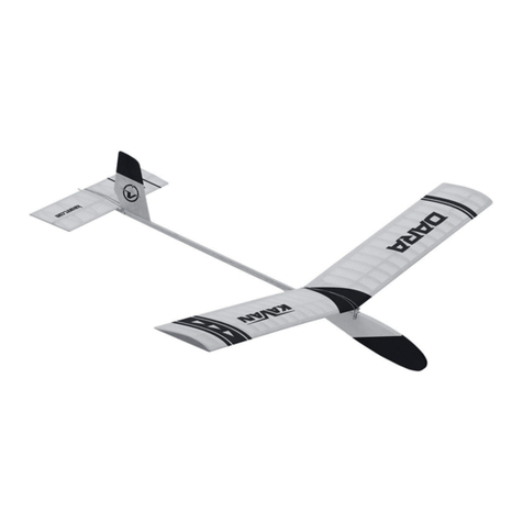
Kavan TARA User manual

Instruction Manual/Návod ke stavbě/Bauanleitung
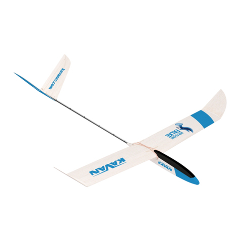
TARA
F1H Glider
Větroň F1H (A1)
F1H (A1) Segler
|

2
NOTICE!
The model you build and y is not a toy! Although it may seem light and slow in ight, it is capable of causing injury or other damage if mistreated. It
is up to you and it is up to you whether you build the model properly, y properly and continue to y in accordance with common practice and rules
(and common sense). If you are just getting started with aircraft models, ask for advice from your model shop or an experienced modeller at your local
modelling club to nd a good instructor.
Before construction: Build the model exactly as instructed. Do not change or modify the model, because if you do, you risk that the model may be
unsafe or unable to y. Take the time to build, build everything rmly and reliably. Use appropriate tools, accessories and other equipment that is in
top condition; correctly install all parts of the model and check the model before the rst and every subsequent ight.
Note: We, as a kit manufacturer, can guarantee you a premium quality kit with detailed instructions, but ight characteristics and performance
depend entirely on how you complete the model. Since we have no control over how you complete and operate the model, we cannot (and cannot be
assumed) assume any responsibility for any damage caused or related to the operation of your completed model.
UPOZORNĚNÍ!
Model, který budete stavět a létat, není hračka! Ačkoliv Vám může připadat lehký a pomalý v letu, je schopen při nesprávném zacházení způsobit
zranění nebo jiné škody.
Je na Vás a jen na Vás, zda model postavíte správně, řádně zalétáte a dále budete létat v souladu s běžnými zvyklostmi a pravidly (a také selským rozu-
mem). Pokud s modely letadel právě začínáte, požádejte o radu ve Vašem modelářském obchodu nebo zkušeného modeláře v místním modelářském
klubu tak, abyste našli dobrého instruktora.
Před stavbou: Model stavte přesně podle návodu. Neměňte nebo neupravujte model, protože pokud tak učiníte, riskujete, že model může být nebez-
pečný nebo neschopný letu. Najděte si čas pro stavbu, stavějte vše pevně a spolehlivě. Použijte odpovídající nářadí, příslušenství a další vybavení, které
je v prvotřídním stavu; správně instalujte všechny části modelu a model kontrolujte před prvním a každým dalším letem.
Poznámka: My, jako výrobce stavebnice Vám můžeme zaručit stavebnici prvotřídní kvality s podrobným návodem, ale letové vlastnosti a výkony
závisí výhradně na tom, jak model dokončíte Vy. Protože nemáme žádnou kontrolu nad tím, jak model dokončíte a provozujete, nemůžeme převzít
(a nemůže být ani předpokládána) jakoukoliv odpovědnost za případné škody způsobené nebo související s provozem Vámi dokončeného modelu.
ACHTUNG!
Das Modell, das Sie bauen und mit dem Sie iegen werden, ist kein Spielzeug! Auch wenn es Ihnen beim Fliegen leicht und langsam vorkommen kann,
ist es fähig, bei falscher Benutzung eine ernsthafte Verletzung oder einen Vermögensschaden zu verursachen.
Es liegt nur an Ihnen, ob Sie das Modell richtig bauen, einiegen und weiter im Einklang mit üblichen Regeln (und auch mit menschlichem Verstand)
iegen werden. Wenn Sie gerade mit Modellen beginnen, bitten Sie um Rat in Ihrem Modellbaugeschäft oder einen erfahrenen Modellbauer im
lokalen Modellbauklub, damit Sie einen guten Instruktor nden.
Vor dem Bau: Bauen Sie das Modell genau nach der Anleitung. Ändern Sie oder passen Sie das Modell auf keine Weise an. Sonst riskieren Sie, dass
das Modell gefährlich oder ugunfähig sein kann. Finden Sie Zeit für den Bau, bauen Sie alles fest und zuverlässig. Verwenden Sie ein entsprechendes
Werkzeug, Zubehör und andere Ausstattung, die im perfekten Zustand ist; installieren Sie alle Teile des Modells richtig und überprüfen Sie das Modell
vor dem ersten und vor jedem nächsten Flug.
Bemerkung: Wir, als Hersteller des Baukastens, können Ihnen den Baukasten erstklassiger Qualität mit einer detaillierten Anleitung gewährleisten,
aber Flugeigenschaften und Leistungen sind ausschließlich davon abhängig, wie Sie das Modell fertig stellen. Da wir keine Kontrolle darüber haben,
wie Sie das Modell fertig stellen und betreiben, können wir keine Verantwortung für etwaige Schäden übernehmen, die mit der In-Betrieb-Setzung
des von Ihnen fertiggestellten Modells verursacht werden.

3
TARA
INTRODUCTION
The F1H glider TARA is a great entry level kit for any modeller who has
already gained some skills in the classic balsa bashing and dope&tissue
covering. You will need some basic modeller‘s tools, glues and dopes –
you will nd these handy with any of your future projects as well. Please
make yourself familiar with the building plans and this manual BEFORE
you actually start the assembly.
SPECIFICATION
Wingspan 1100 mm
Length 828 mm
All-up Weight 225 g (min. 220 g)
BEFORE YOU START
Glue: You can use acetone based modeller‘s glue (UHU® Hart etc.), water
resistant white glue (KAV9960 KAVAN White Glue, BISON® Super Wood
etc.) or medium cyano (Power CA, KAV9952 KAVAN Medium CA etc.).
Dope: KAVAN Classic line Adhesive dope (KAV9987), Shrinking dope
(KAV9986), Top gloss dope (KAV9989) and Thinner (KAV9990) are the
must for the dope and tissue covering, indeed.
Tools and Accessories: You will need a perfectly at building board
(at least 300x700 mm), modeller‘s knife (Excel K1 w. No.11 blades etc.),
jigsaw, sanding blocks with 180 and 360-400 grit sandpaper, model hob-
by pins, scissors, sharp model hobby knife, at and round ne le, soft
at (1/4“-3/8”) brush, thin clear plastic lm to protect the building plan (a
large PE bag cut in half will work).
ASSEMBLY
• Lay the wing building plan on the building board and put a sheet of a thin
clear plastic lm to protect the building plan. If you have got just a small
building board, you can carefully cut the building plan into sections –
wing section, horizontal tailplane section etc.
• Before you apply the glue, please, always double check the correct size, shape
and alignmentoftheparticularpart.
• Balsa and spruce sticks are intentionally supplied oversized in the kit. Pin
the stick to the plan overlapping at both ends – you will cut/sand them
to the correct length/shape once the assembly of the particular part has
been nished.
Wing
There are the wing centre section and both two wing outer panels drawn on
the building plan – so you can assembly them simultaneously, if you wish.
Pin the left half of the tapered balsa trailing edge 3a to the building plan
carefully matching the pre-cut notches with the ribs drawn on the plan.
Attach the other half of the trailing edge 3b to the 3aandcheck whether the
notches are matching. If yes glue the 3b to the 3a and pin down to the plan.
If the notches do not match, trim the trailing edge 3b as necessary to t.
Lightly sand the CNC milled balsa ribs 1(Det. G-G) to remove any imper-
fections.
Pin down the pre-shaped balsa leading edge 2. Glue the balsa ribs 1in pla-
ce. Fit, cut to size and glue the bottom1.5 mm balsasheeting 4betweenthe
leading and trailing edge. Glue two ribs 6inset about 2 mm along the outer
edge of the central sheeting and another one in the centre of the sheeting.
Glue the balsa end rib 5in place – the bevelled side outwards (in similar
manner to Det. F-F).
Glue the wing main spar 7(3x8 mm spruce stick) into the notches in the
upper side of ribs (trim the bottom edges slightly to slip easier in). Glue only
the bottom ofthemain spar to ribs 5;insert partly thewing joiners42 along
the sides of the main spar in order to get the correct alignment in the wide
notches (DO NOT glue the joiners yet!). Fit and glue the upper central
sheeting8and 9(Det.B-B) in place. Apply some additional glue to all joints
if necessary and let cure.
Once the glue has cured thoroughly remove the wing centre section from
the building plan and sand the leading edge, trailing edge and main spar
ush with the edge of the bevelled outer ribs 5. Sand the leading edge to
the shape (Det. D-D).
Thewingpanels areto bebuilt in thesimilarmannertothewing centresec-
tion. Pin the tapered balsa trailing edges 40 to the building plan carefully
matching the pre-cut notches with the ribs drawn on the plan.
Lightly sand the CNC milled balsa ribs 41-46 to remove any imperfections.
Pin down the pre-shaped balsa leading edges 48. Glue the balsa ribs 41-
46 in place; bevel the front edge of the ribs in order to match the leading
edge 48 perfectly. In similar manner lightly sand the bevelled root ribs 47
to match the leading and trailing edges and glue them in place (Det. F-F).
Glue the wing panel main spars 49 (3x8 mm spruce stick) into the notches
in the upper side of ribs. Glue only the bottom of the main spar to ribs 47;
insert partly the wing joiners 42 along the sides of the main spar in order to
getthe correctalignmentin thewide notches(DONOTglue thejoiners yet!).
Trim the gussets 51 as necessary and glue in place. Apply some additional
glue to all joints if necessary and let cure.
Once the glue has cured thoroughly remove the wing panels from the buil-
ding plan and sand the leading edge, trailing edge and main spar ush with
the edge of the bevelled outer ribs 47. Glue the wing tips 50 in place; once
cured, sand them to the shape. Sand the leading edge to the shape (Det.
D-D).
Trial t the wing centre section and wing panels – if attached together the
wing panel dihedral must be 100 mm (Det. E). Once satised, glue the
plywood wingjoiners42 to the wingcentresection mainspar 7. Applya ge-
nerous amount of glue to wing centre section end ribs, wing panel root ribs
and wing joiners 42 and attach the wing panels to the wing centre section.
Lay the wing centre section down on the building board; secure it with a
couple of magazines wrapped in a plastic bag serving as a weight. Align the
wing panels so their tips were 100 mm above the building board (you can
use a couple of books or a wooden block). Let the glue cure thoroughly. Once
cured, carefully sand the joints and the entire wing using sanding blocks
with a coarse and then ne sandpaper to smooth any rough areas.
Once the dope has cured, sand the entire wing frame with ne sandpaper.
The wing is ready to covering now.

4
Horizontal Tailplane
The horizontal tailplane is to be built directly on the plan protected with
a clear plastic lm in similar manner as the wing. Pin down the spruce
trailing edge (3x5x405 mm) 11 overlapping on both two ends. Glue the
balsa centre plate (3mm– 30x80 mm)13 tothe trailing edge 11.Glue the
spruce leading edges (3x5x197 mm) 10 to the centre plate and pin them
down overlapping on both two ends. Cut to size and glue in place the dia-
gonal ribs 12 made of 3x5 mm balsa stick. Start with the outer diagonal
ribs rst; then proceed towards the centre of the horizontal tailplane.
Glue the spruce main spar 14 (3x5x395 mm) to the top of the horizontal
tailplane framework. Fit and glue the front balsa upper plate 16 (3 mm
– 30x30 mm) and two rear plates (3 mm – 13.5x45 mm) 17. Align the
outer edges of the plates 17 to match the bottom plate 13 leaving about
2.5 mm slot between them to t the bamboo dowel 18 later. Sand the
gussets 15 to t and glue them in place.
Once the glue has cured thoroughly, remove the horizontal tailplane from
the building plan. With a sanding block, shape the tips and centre plates as
indicated on the plans (Det. A-A).Round the leading andtrailing edges and
the tips (Det. A-A). The horizontal tailplane has been nished for now; once
covered with the tissue, glue the bamboo dowel (Φ2.5x50 mm) 18 between
the plates 17 extending behind the trailing edge by 15 mm.
Fuselage and Fin
The fuselage consists of the tail boom made of spruce sticks and balsa
blocks and the front fuselage block made of Ceiba plywood with poplar
plywood side covers oering enough space for the ballast and timer (if
you decided to install one).
Start with the tail boom; glue it on the building board in order to make
the tail boom true and straight. Glue the front balsa block 20 to the
spruce stick (2x8x600 mm) 22 taking care the outer edges of the block
matched the edges of the stick. Note – the rear balsa block 21 will be
glued to the bevelled side of the front block later. Now apply glue to the
rear part of the spruce stick 22 and block 20; attach the rear balsa block
21 matching the edges of the stick. Glue the other 2x8 mm spruce stick
23 to the tail boom.
If you consider installing a timer (either mechanic or electronic) and
dethermalizer, now it is the time to trim the openings in the fuselage
block 24 as needed. Do not forget to cut appropriate opening in one of
the side covers (26 or 28) as well.
Insert the tail boom in the notch in the fuselage block 24. Trim the notch
if necessary. Remove the tail boom, apply a generous coat of glue into the
notch and insert the tail boom. Glue it on the building board in order to
make the fuselage true and straight.
Insert the two beech dowels 25 (Φ4x32 mm) into the fuselage – no glue
yet; the dowels will help with the correct alignment of the side covers.
Apply glue to the left side of the fuselage block; align and attach the side
cover 26. You can lay the fuselage down onto your building board and
weigh the cover down to cure. Insert and glue the main ballast 27 into
the nose opening. Glue the other side cover 28 in place.
Glue the reinforcement plate 30 into the n 29. Make the front horizontal
tailplane seat: Glue the spruce stick (3x5x25 mm) 32 to the plywood plate
(1 mm - 25x15 mm) 31.
Mark the position of the tailplane seat to the fuselage according to the
building plan and glue it to the tail boom. Lay the horizontal tailplane
down on the seat in order to check the tailplane was square to the fusel-
age sides (when looking from the nose to the tail) and also square to the
longitudinal axis of the fuselage (when looking from above). Glue the rear
tailplane seat (balsa 1.5 mm – 8x10 mm) 33 to the fuselage. Glue the n
29 to the fuselage. Use the horizontal tailplane as a reference again; the
n has to be square to the horizontal tailplane and exactly in the longi-
tudinal axis of the fuselage. Round the leading and trailing edges of the
rudder 52; the brass rudder hinges 45 will be installed after dopind and
covering of the model.
Now glue the plywood wing seat plate 36. Keep it centred and square to
the side of the fuselage.
Glue the beech wing hold-down dowels 25 into the fuselage. Mark the
position of the holes for the horizontal tailplane hold-down dowels 34
and 35 (bamboo Φ2.5x25 mm) and glue them in place. Glue the balsa
bottom n 37 to the fuselage.
Doping and Tissue Covering
Lightly sand the entire airframe with the ne sand paper. Before the
frames are covered, all EXTERNAL surfaces MUST be primed with the ad-
hesive dope (diluted at least 1:1 with the thinner; the dope must have the
viscosity of water - never use the dope unthinned!). Use a soft at brush
to apply the dope and, when dry, lightly sand all doped surfaces with the
ne sandpaper. Apply the second coat, sand lightly again.
Sheets of the Vlies covering tissue are supplied in the kit. You can glue
it to the airframe using water thinned white glue or clear dope. Always
align the „grain“ of the tissue the long way - from tip to tip of the wing
or horizontal tailplane.
Horizontal Tailplane: If you are new to the dope and tissue business,
you should start with the horizontal tailplane in order to gain the skills on
smaller part of your model featuring no curves. Cut a piece of the tissue 10
mm oversized all around the outline of the horizontal tailplane. Apply the
thinned white glue or adhesive dope around the external edges of the lower
side of the tailplane and to the diagonal ribs and centre plate; IMMEDIATELY
set the tissue in position and smooth the edges with nger tips before it has
a chance to dry. Cut the tissue all around the outline of the tailplane leaving
it 4-5 mm over size. Bend and glue with thinned white glue or clear dope the
overlapping tissue around the entire tailplane.
Cover the upper side of the tailplane in the same manner – apply thinned
white glue/adhesive dope to the trailing and leading edges, main spar,
centre plates and tips. Do not apply the glue to the diagonal ribs!
Wing: Cut four or six pieces (a skilled builder could cover the entire bo-
ttom side of the wing using just one long strip of tissue; the upper side of
the wing centre section and wing panels are to be covered by separate
strips) of the tissue 10 mm oversized all around the outline (do not forget
the upper sheets have to be wider due to the airfoil camber). Again, start
with the bottom side of the wing – apply the glue/dope to the leading
and trailing edges and all ribs, attach the tissue and smooth the edges
with nger tips. Cut the tissue all around the outline of the wing leaving
it 4-5 mm over size. Bend and glue with thinned white glue or adhesive
dope the overlapping tissue around edges of the entire wing. You will
have to cut the tissue against the wing panels joints and in short 4-8 mm
portions around the wing tip in order to follow the curve of the tip.
Cover the upper side of the wing centre section in the same manner (the
tissue overlapping over the wing panel root ribs 47) – apply thinned
white glue/adhesive dope to the trailing and leading edges, main spar
and ribs.
Cover the wing panels with separate strips of tissue; attach the tissue to
the rib, using a pencil and steel ruler or a piece of exible plastic draw
the line marking the joint of 5and 47 ribs on the tissue. Trim the tissue
to the line and glue in place in the usual manner. You will have to cut the
tissue in short 4-8 mm portions around the wing tip in order to follow
the curve of the tip.

FLYING
Once again check the correct position of the centre of gravity, check for
any excessive warping of the wing, tailplane and fuselage. Choose a nice
calm day for the rst ight.
The model must be launched into the wind every time. Throw grass into
the air to observe the wind direction.
Hold your model with the wing and fuselage level. Launch your model
with a gentle push straight with the nose pointing slightly down. Do
not throw your model with nose up, or at greater angle than 10 degrees
down. The model must have a certain minimum speed from the very start
to stay airborne. It is not enough to just place your model in the air. It is
better to land in tall grass in order to prevent any damage to your model
during initial trimming.
If everything is OK (correct wing and tailplane alignment, correct CG po-
sition) TARA will y with the wings level in a nice glide with her nose po-
inting slightly down. If the model glides straight down to the earth a few
paces in front of you, check the CG position again. If OK, add a thin piece of
balsa or plywood under the trailing edge of the horizontal tailplane until
the model glides in a nice at and straight path.
Once satised, bend the rudder 52 slightly (about 2 mm) to the left (looking
from the tail to the nose). Now the model should glide in large left (counter
clockwise) turns; whilst under tow, the o-centre towhook would force your
TARA right - resulting in straight ight.
Once trimmed out you can try your rst hi-start with your TARA using 25-
50 m towline (a shing line). You can purchase a towline set in your local
model hobby shop or you can make your own from scratch. Get a towline
(any shing line strong enough to hold 5 kg sh is OK), tie a key ring to one
end (bowline knot is the best) and a ag (a piece of red cloth) 20-30 cm
from the end. Theagmakes thetowlinevisible intheairaswell as onthe
ground. Find a suitable spool to keep the towline on.
Hook the ring at the towhook and ask a friend to hold (and launch later)
your model. Unwind the towline walking into the wind keeping is slightly
stretched. The launch position of the model: wings level, nose very slight-
ly up, directly into the wind.
Give a signal to your friend holding your model; both of you will start
running into the wind, the assistant will launch the model after a few
paces. Continue running into the wind paying attention to the tension
of the towline and checking the model over your shoulder. Run as fast
as necessary to achieve steady climbing rate of your model – the model
should climb straight forward, at steady rate, in a nice arc. The stronger
the wind, the slower you might run. If the towline tension decreases, your
model climbs slowly (and yaws to a side) you should run faster. If the tow-
line tension increases and the model violently turns to a side, you have
to slow down and wait until the model returns to the original straight
path. Hi-start requires some skills; especially on a windy day running too
fast might even end in destruction of your model. Once the mode climbs
almost over your head, it should start turning slightly left – this is the
moment to stop. Let the model y in front of you and release the towline.
For the initial high start, set the towhook to the forward position. Based
on the TARA´s behaviour you can move it back/adjust later. If your model
hesitates to climb, move it back; if pitches the nose up and veers to side,
move it forward. Adjust the rudder to achieve large at left turns; tight
banked turns kill the altitude! Usually, just 2 mm left oset is OK. Contest
yers would want to install the dethermalizer with a timer that kicks the
horizontal tailplane up (about 45°) once the set time has elapsed; the mo-
del will land in large „hoops“ then.
Have a ball, enjoy your TARA!
KAVAN Team
5
You can cover the tail boom as well (apply 4 slightly overlapping strips
to the bottom both sides and nally to the top of the boom) to add some
extra strength; there is no need to cover the nose.
Now you can apply several coats of thinned shrinking dope in order to
shrink the tissue and protect it from moisture. Once the tissue is nice and
smooth without wrinkles (after 1-2 coats) you can apply the colour tissue
trim – and continue in applying the shrinking dope.
Onlyapply the dope ina dry and well ventilated area at room temperature
(over 20°C; low temperature/high humidity may cause „fogging“ of some
dopes turning them milky white instead of clear – if that happens you can
usually cure it by taking the model to a dry and warm place and applying
just the fresh thinner with a brush to the „fogged“ part). Apply 3 to 5
coats of thinned dope to the entire model (use the top gloss dope for the
fuselage and the last coat for the wing and horizontal tailplane). Lightly
sand all doped surfaces with ne sandpaper between each coat.
Apply the colour tissue trim to the fuselage before the last coat of dope
(use the top gloss dope for the nal coat). The stickers are to be
applied only after the nal coat!
Let the model dry thoroughly after each coat (2-3 days). Check for any
warping of the wing or horizontal tailplane. If that happens, you have to
lay the wing and/or tailplane down to a at surface protected with a plas-
tic lm and weigh it down (a couple of magazines in a plastic bag to the
rescue again) after each coat. Let it dry thoroughly.
Final Assembly, Centre of Gravity (CG)
Secure the side towhook 39 to the left side of the fuselage using two
screws 38 – refer to the building plan. The towhook is adjustable – you
can move it forward on a windy day or backward on a calm day in order to
achieve nice and steady climbing during the hi-start.
Use the tip of a pointy modeller’s knife to cut slots for the brass tin rudder
hinges 53 into the n 29 and rudder 52. Cyano the hinges into the rudder
and then into the n leaving a slight gap between the n and rudder.
Tie the wing and horizontal tailplane to the dowels on the fuselage using
several loops of the supplied rubber thread. Please note – one loop is
never enough!
Drill 5 mm access hole into the additional ballast compartment in the
fuselage (refer to the building plan). Support the wing of the model with
your ngertips in the centre of gravity position (the point marked by an
arrow on the fuselage plan). The fuselage should be level - if the nose
pitches up put in as much of additional ballast (not supplied in the kit) as
necessary (you can use pellets, small screws etc.) Once satised, cover the
hole with a strip of clear sticky tape.
The correct balancing is essential; incorrectly balanced model will be di-
cult to set up or unable to y at all!

6
THE KIT CONTENTS
Part Building Plan No. Qty.
Fuselage Block – 8 mm Ceiba plywood (24) 1
Side Cover – 3 mm poplar plywood (26, 28) 2
Vlies Tissue Sheet (1230x330 mm) 1
Vlies Tissue Sheet (200x410 mm) 1
Colour Tissue Trim Sheet 2
Sand Paper 1
Building Plan 1
Instruction Manual 1
Stick Bundle A
Fuselage stick - spruce 2x8x595 mm (22, 23) 2
Wing Leading Edge - balsa 8x8x645 mm (2) 1
Wing Main Spar - spruce 3x8x645 mm (7) 1
Stick Bundle B
Wing Leading Edge - balsa 8x8x260 mm (48) 2
Wing Trailing Edge - balsa 14x4,7x330 mm (3a, 3b) 2
Wing Trailing Edge - balsa 14x4,7x260 mm (40) 2
Spruce Stick 3x5x405 mm (11) 1
Spruce Stick 3x5x395 mm (14) 1
Spruce Stick 3x5x197 mm (10) 2
Spruce Stick 3x8x245 mm (49) 2
Balsa Fuselage Block – thick (20) 1
Balsa Fuselage Block – thin (21) 1
Balsa Stick 3x5x300 mm (12) 6
Rib Set Bag A
Main Wing Rib (1) 14
Support Rib (6) 3
Wing End Rib (bevelled) (5) 2
Rib Set Bag B
Wing Panel Root Rib (bevelled) (47) 2
Wing Tip (50) 2
Wing Panel Rib (41-46) 12
Bag C
Fin (29) 1
Bottom Fin (37) 1
Wing Seat Plate – plywood 1.5 mm (36) 1
Wing Centre Sheeting - balsa 1.5 mm (4, 8, 9) 6
Small Parts Bag D
Balsa Plate – balsa 3 mm – 30x80 mm (13) 1
Balsa Plate – balsa 3 mm – 30x30 mm (16) 1
Balsa Plate – balsa 3 mm – 13,5x45 mm (17) 2
Wing Joiner „V“ (42) 4
Gusset (10, 15, 51) 18
Small Parts Bag E
Rudder (52) 1
Fin Reinforcement Plate (30) 1
Rear Hor. Tailplane Seat – balsa 1.5 mm –
8x10 mm (33) 1
Towhook (39) 1
Rubber Thread Φ1x600 mm 1
Part Building Plan No. Qty.
Hor. Tailplane Seat - plywood 1 mm -
25x15 mm (31) 1
Spruce Stick - 3x5x25 mm (32) 1
Bamboo Dowel Φ2,5x25 mm (34, 35) 2
Bamboo Dowel Φ2,5x50 mm (18) 1
Beech Dowel Φ4x32 mm (25) 2
Screw 2x8 mm (38) 2
Ballast Φ26x8mm (27) 1
Rudder Hinge (brass tin) (53) 2

7
TARA
ÚVOD
Větroň kategorie F1H (A1) TARA je určen začínajícím modelářům, kteří
již mají zkušenosti se stavbou jednoduchých házedel a menších modelů
potahovaných papírem. Budete potřebovat základní modelářské nářadí,
lepidla a laky, které v budoucnu využijete i při stavbě dalších modelů.
Před zahájením stavby, prosím, důkladně prostudujte návod ke stavbě a
stavební výkres.
TECHNICKÉ ÚDAJE
Rozpětí 1100 mm
Délka 828 mm
Hmotnost 225 g (min. 220 g)
NEŽ ZAČNETE
Lepidla: Můžete použít acetonová modelářská lepidla (UHU® Hart, Ka-
nagom apod.), voděodolná disperzní lepidla (KAV9960 KAVAN Disperzní
lepidlo, BISON® Super Wood apod.) nebo střední vteřinové lepidlo (Power
CA, KAV9952 KAVAN CA střední apod.).
Laky: Lepící (KAV9987), napínací (KAV9986) a lesklý (KAV9989) lak a ře-
didlo pro ně (KAV9990) z řady KAVAN Classic.
Nářadí a další potřeby: Dokonale rovná pracovní deska, do níž je mož-
no zapichovat špendlíky (např. laťovka nebo spárovka aspoň 300x700
mm), modelářský nůž s výměnnými čepelemi (např. Excel K1 s čepelemi č.
11), lupenková pilka s jemnými listy, brousítka s brusným papírem č. 180
a 360-400, modelářské špendlíky, nůžky, plochý a kulatý jehlový pilník,
měkký plochý vlasový štětec, tenkou čirou plastovou fólii na zakrývání
stavebního plánu (např. rozříznutý velký polyetylénový sáček, zakrývací
fólie pro malíře pokojů apod.).
STAVBA MODELU
• Stavební výkres položte na rovnou pracovní desku a překryjte jej tenkou
čirou plastovou fólií, která jej bude chránit před přilepením kostry modelu.
Máte-li jen malou pracovní desku, plánek můžete opatrně rozstřihnout na
menší části – např. s křídlem, vodorovnou ocasní plochou atd.
• Než díly přilepíte na místo, vždy předem na sucho, bez lepení vyzkoušejte,
zda správně lícují.
• Balsové a smrkové nosníky a lišty jsou ve stavebnici o něco delší, než je
třeba. Při lepení ponechejte přesah na obě strany, na přesnou délku se
oříznou/zabrousí až po dokončení příslušné části modelu.
Křídlo
Křídlo má na stavebním výkresu nakreslenou střední část i obě uši,
takže je můžete stavět současně, pokud chcete. Levou polovinu balsové
(lichoběžníkové) odtokové lišty 3a přišpendlete (aspoň 3 špendlíky) na
pracovní desku s plánkem tak, aby se drážky v odtokové liště kryly s žebry
nakreslenými na plánku. Druhou polovinu odtokové lišty 3b přiložte na
plánek k odtokové liště 3a a zkontrolujte, zda se drážky v odtokové liště
se kryjí s žebry nakreslenými na plánku. Pokud ano, odtokovou lištu 3b
přilepte k liště 3a a zajistěte špendlíky. Pokud je odtoková lišta 3b delší,
před slepením ji zkraťte, aby drážky v liště odpovídaly poloze žeber.
Hotová balsová žebra 1(Det. G-G) začistěte jemným brusným papírem.
Na plánek lehce přišpendlete tenkými špendlíky lichoběžníkovou náběž-
nou lištu 2. Mezi náběžnou a odtokovou lištu křídla vlepte balsová žebra
1. Dále pak mezi náběžnou a odtokovou lištu křídla vlepte (po seříznutí na
správnou šířku) spodní střední balsový potah 4ze dvou 1,5 mm balsových
prkének. Na tento potah nalepte asi 2 mm od jeho okrajů a do středu kří-
dla tři snížená žebra 6. Na konce střední části křídla přilepte balsová žebra
5– se zbroušeným úkosem směrem ven (podobně jako Det. F-F).
Shora do zářezů v žebrech vlepte hlavní nosník křídla 7ze smrkové lišty
3x8 mm (pro snadnější zasouvání zaoblete spodní hrany nosníku). Nosník
přilepte ke koncovým žebrům 5pouze na jeho spodní straně; správnou
polohu v zářezu získáte částečným nasunutím spojek křídla 42 po obou
stranách hlavního nosníku (pozor, aby se nepřilepily). Na žebra 6nale-
pená na spodním balsovém potahu přilepte i přední a zadní díl horního
balsového potahu křídla 8a 9(Det. B-B). K náběžné a odtokové liště (do
rohů) nalepte výkližky 10. Spoje žeber s náběžnou i odtokovou lištou a
nosníkem znovu ve všech místech spojení přetřete lepidlem a nechejte
řádně zaschnout.
Po zaschnutí lepidla střední část křídla sejměte s plánku a zabruste hlavní
nosník, náběžnou a odtokovou lištu na obou koncích střední části křídla
do roviny se zkosenými koncovými žebry 5. Náběžnou hranu zabruste do
tvaru prolu (Det. D-D).
Vnější části křídla – uši – se staví podobným způsobem jako střední část
křídla. Balsové (lichoběžníkové) odtokové lišty 40 přišpendlete na pra-
covní desku s plánkem tak, aby se drážky v odtokové liště kryly s žebry
nakreslenými na plánku.
Hotová balsová žebra 41-46 začistěte jemným brusným papírem.
Na plánek lehce přišpendlete tenkými špendlíky lichoběžníkové náběžné
lišty 48. Mezi náběžnou a odtokovou lištu křídla vlepte balsová žebra 41-
46; jejich přední hranu opatrně zabruste do úkosu, aby žebra dosedala
celou plochou na náběžnou lištu 48. Kořenová žebra uší 47 předem za-
bruste tak, aby řádně lícovala s náběžnou a odtokovou lištou a vlepte je
na místo.
Shora do zářezů v žebrech vlepte hlavní nosníky uší 49 ze smrkové lišty
3x8 mm. Nosník přilepte ke koncovým žebrům 47 pouze na jeho spodní
straně; správnou polohu v zářezu získáte částečným nasunutím spojek
křídla 42 po obou stranách hlavního nosníku (pozor, aby se nepřilepily).
K náběžné a odtokové liště (do rohů) nalepte výkližky 51, které předem
zabrousíte do správného tvaru. Spoje žeber s náběžnou i odtokovou lištou
a nosníkem znovu ve všech místech spojení přetřete lepidlem a nechejte
řádně zaschnout.
Po zaschnutí lepidla obě uši sejměte s plánku a zabruste hlavní nosník,
náběžnou a odtokovou lištu na obou koncích střední části křídla do roviny
se zkosenými koncovými žebry 47. Na konce obou uší přilepte koncová
žebra 50, po zaschnutí lepidla zaoblete jejich hrany do tvaru dle plánku.
Náběžnou hranu zabruste do tvaru prolu (Det. D-D).
Znovu překontrolujte zbroušení koncových žeber střední části křídla a
kořenových žeber obou uší – po přiložení uší ke střední části křídla k sobě
musí být vzepětí obou uší shodně 100 mm (Det. E). K hlavnímu nosníku

8
7přilepte z obou stran překližkové spojky křídla 42. Styčné plochy zkose-
ných žeber a vyčnívající spojky 42 natřetedůkladnělepidlem apoté jedno
po druhém přilepte obě uši tak, že střední část křídla položíte na rovnou
pracovní plochu a zatížíte (např. opatrně položenými časopisy uloženými
v plastovém sáčku). Uši přitlačte ke střední části křídla na pracovní desce
a podložte je například dřevěným špalíkem nebo knihami tak vysoko, aby
konec ucha byl ve výšce 100 mm nad pracovní deskou. Lepidlo pak ne-
chejte důkladně vytvrdit. Poté spoje uší přebruste, následně i celé křídlo.
Vodorovná ocasní plocha
Vodorovná ocasní plocha (zkráceně VOP) se stejně jako křídlo staví přímo
na plánku chráněném čirou plastovou fólií. Smrkovou odtokovou lištu
(3x5x405 mm) 11 přišpendlete na výkres výškovky s přesahem na obě
strany. K odtokové liště 11 přilepte balsovou podložku (tl. 3mm) 13 a
následně k ní smrkové náběžné lišty (3x5x197 mm) Mezi náběžnou a od-
tokovou lištu vlepte šikmé balsové výztuhy 12, které si postupně nařežete
z balsových lišt 3x5mm. Výztuhy lepte postupně od vnějších konců VOP
směrem ke středu VOP.
Na horní část VOP nalepte smrkový nosník 14 (3x5x395 mm). Na balsovou
podložku 13 přilepte horní přední balsovou podložku (tl. 3mm – 30x30
mm) 16 a dále pak 2 ks zadních balsových podložek (tl. 3 mm – 13,5x45
mm) 17. Obě tyto zadní podložky se přilepí na podkladovou balsovou
podložku 13 tak, aby byly zároveň v rovině boční hrany podložek (horní i
spodní)amezi oběmahornímipodložkami17 byla mezera asi 2,5 mm pro
zalepení bambusového kolíku 18. Do vnějších rohů VOP vlepte výkližky
15, které předem zabrousíte do správného tvaru.
Po dokonalém zaschnutí lepidla VOP sejměte z plánku, zařízněte přesahy
náběžné a odtokové hrany a zaoblete je brusným papírem do tvaru prolu
(Det. A-A). Do tvaru prolu (Det. A-A) zabruste i střední horní balsové
podložky. Po potažení výškovky papírem mezi balsové podložky 17 vlepte
bambusový kolik (bambusová kulatina Φ2,5x50 mm) 18 tak, aby přesa-
hoval odtokovou hranu VOP o 15mm.
Trup a svislá ocasní plocha
Trup má tyčkový nosník ocasních ploch a vpředu hlavici potaženou to-
polovou překližkou s dostatkem místa pro zátěž a případnou instalaci
časovače. Začněte ocasním nosníkem: Na lištu (2x8x595 mm) 22 přilepte
na „tupo“ přední balsový hranol trupu 20 – okraje hranolu jsou v rovině
s okraji lišty – POZOR – na šikmou stranu hranolu později bude nalepen
zadní balsový hranol 21 – viz výkres. Nyní naneste lepidlo na zbylou část
lišty 22 i šikmou část balsového trupu 20 a následně přilepíte (v rovině
s okraji lišty) i zadní hranol trupu 21. Na druhou lištu trupu 2x8 mm 23
naneste lepidlo a na rovné podložce ji přilepte k již slepeným částem
ocasního nosníku.
Pokud hodláte používat časovač, je nyní vhodná doba, abyste pro něj dle po-
třeby upravili výřez v hlavici trupu 24 a vyřízli odpovídající otvor v jednom z
bočních krytů (26 nebo 28).
Slepený ocasní nosník vložte do drážky v hlavici trupu 24. Šířku drážky dle
potřeby upravte pilníkem. Poté ocasní nosník z hlavice vyjměte, naneste
na něj lepidlo a vložte zpět do hlavice trupu. Ocasní nosník s hlavicí lepte
na rovné desce, aby byl celý trup po slepení rovný.
Na sucho, bez lepení zasuňte 2bukové kolíky 25 (Φ4x32 mm) do hlavice
trupu. Tyto kolíky poslouží k přesnému umístění bočních krytů hlavice.
Na jednu stranu hlavice trupu naneste lepidlo a na bukové kolíky nasaď-
te boční kryt trupu 26 a přitiskněte jej k hlavici. Oba lepené díly můžete
položit na pracovní desku a zatížit je závažím. Do hlavice trupu vložte a
zalepte) zátěž 27. Obdobným způsobem přilepte i druhý boční kryt trupu
28.
Do svislé ocasní plochy (zkráceně SOP) 29 vlepte výztuhu 30. Dále slepte
lože vodorovné ocasní plochy. Na překližkovou podložku (tl. 1 mm - 25x15
mm) 31 přilepte smrkovou lištu (3x5x25 mm) 32. Ze stavebního výkresu
odměřte vzdálenost umístění lože VOP od konce trupu a lože VOP nalepte
na trup. Je nutno kontrolovat, aby lože VOP bylo přilepeno tak, aby při
pohledu zepředu byla VOP položená na lože kolmá na boky hlavice trupu
a při pohledu shora byla její náběžná hrana kolmá na podélnou osu trupu.
Na konec trupu přilepte balsovou podložku (tl. 1.5 mm – 8x10 mm) 33. Na
trup (kolmo na VOP) přilepte svislou ocasní plochu 29. Zaoblete náběžnou
a odtokovou hranu směrovky 52; směrovku a její závěsy 53 nainstalujete
až po potažení a nalakování modelu.
Nyní přilepte překližkové lože křídla 36 tak, aby jeho střed byl v podélné
ose trupu a lože bylo kolmé na oba boky trupu.
Do hlavice trupu zalepte oba poutací kolíky křídla 25. Dle stavebního vý-
kresu označte na zadní části trupu místo pro vyvrtání otvorů pro poutací
kolíky výškovky (bambusová kulatina Φ2,5x25 mm) 34 a 35. Ke spodní
části trupu přilepte balsovou ostruhu 37.
Lakování a potahování
Celý model opatrně přebruste jemným brusným papírem a 2x nalakujte
velmi řídkým lepícím lakem (zředěný ředidlem v poměru nejméně 1:1 –
lak musí téci jako voda; nikdy nepoužívejte neředěný lak). Po zaschnutí
každé vrstvy laku celý model znovu přebruste jemným brusným papírem.
Potah modelu je z papíru Vlies. Papír můžete ke kostře modelu přilepit
vodou naředěným disperzním lepidlem nebo jej můžeme rovnou přilako-
vat řídkým lepicím lakem. Papír orientujte vlákny ve směru rovnoběžném
s hlavním nosníkem křídla nebo vodorovné ocasní plochy, nikoliv napříč.
VOP: Nemáte-li ještě větší zkušenosti s potahováním, doporučujeme
začít s vodorovnou ocasní plochou, na které si potahování „nacvičíte“.
VOP potáhněte nejprve zdola jedním pruhem papíru uříznutým tak, aby
po obvodu byl všude přesah aspoň 10 mm – lepidlem natřete náběžnou
a odtokovou lištu a všechna žebra. Papír přiložte na kostru a opatrně při-
hlaďte (pokud používáte lepení lakem, po přiložení papíru na kostru jej
přilakujte po celé ploše řídkým lepícím lakem). Po zaschnutí lepidla (laku)
potahový papír po obvodu ořízněte tak, aby zůstal přesah 4-5 mm. Přesa-
hující papír ohněte dle hrany a přilepte (přilakujte) ke kostře.
Poté VOP potáhněte stejným způsobem jedním pruhem papíru shora –
lepidlem natřete náběžnou a odtokovou lištu, hlavní nosník, střední bal-
sovou výplň a koncová žebra. Šikmá balsová žebra nenatírejte!
Křídlo: Křídlo potáhněte 4-6 pruhy papíru (spodní stranu křídla zkuše-
nější stavitel potáhne jediným pruhem, shora je nutno potahovat zvlášť
střední část křídla a obě uši), které nastříháte s přesahem aspoň 10 mm
po celém obvodu (nezapomeňte, že pruhy pro horní stranu křídla musejí
být širší – horní strana křídla je klenutá). Potahovat začněte opět zespo-
du – lepidlo naneste na náběžnou a odtokovou lištu a všechna žebra,
přiložíte pruh papíru na spodní stranu křídla a papír přihlaďte prsty ke
kostře. Po zaschnutí lepidla (laku) potahový papír po obvodu ořízněte tak,
aby zůstal přesah 4-5 mm. Přesahující papír ohněte dle hrany a přilepte
(přilakujte) ke kostře. V místě lomení křídla je nutno přesahující papír
proříznout a na okrajích koncového oblouku nařezat na krátké (4-8 mm)
úseky a ty poté postupně přilakovat.
Poté obdobným způsobem potáhněte jedním pruhem papíru horní stra-
nu střední části křídla (s přesahem na kořenová žebra uší 47) – lepidlo
naneste na náběžnou a odtokovou lištu, hlavní nosník a všechna žebra.
Přesahující papír již známým postupem ořízněte, ohněte dle hrany a při-
lepte (přilakujte) ke kostře.
Poté potáhněte vždy jedním pruhem papíru obě uši; papír vždy nejprve
přiložte k uchu, tužkou podle ohebného ocelového pravítka na něj narý-
9
sujte čáru v místě lomení křídla (mezi žebry 47 a 5) a papír dle ní zastři-
hněte a nalepte již známým postupem. Na okrajích koncového oblouku
je nutno přesahující papír nařezat na krátké (4-8 mm) úseky a ty poté
postupně přilakovat.
Ocasní nosník můžete pro zvýšení pevnosti rovněž potáhnout papírem
(4 pruhy s malým přesahem postupně zespodu, z obou boků na konec
shora); hlavici trupu není potřeba potahovat. Potah křídla a VOP je poté
možno vypínat zředěnýmnapínacím lakem. Jakmileje potahrovnoměrně
napnutý (po 1-2 vrstvách laku), můžete přilakovat barevné papírové do-
plňky – a pokračovat v lakování.
Celý model nalakujte za sucha a teploty nad 20°C (některé druhy laků mají
tendenci při nižší teplotě a vysoké vlhkosti vzduchu bělat – pokud se tak
stane, zpravidla pomůže přemístění do suchého a teplého prostředí a
opatrné přetření modelu čerstvým ředidlem používaným pro ředění laku),
celkem 3-5 vrstev velmi řídkým lakem. Na trup po natření bezbarvým lakem
a následném přebroušení můžete přilakovat barevné papírové doplňky -
vyznačení kabiny apod. Mezi jednotlivými nátěry necháme lak několik dnů
schnout – sledujete také, zda se křídlo nebo VOP nekroutí. V případě, že
by došlo k většímu deformování, je nutno takový díl po každém lakování
položit na rovnou desku chráněnou plastovou fólií, zatížit (opět pomohou
časopisy vložené do plastového sáčku) a nechat důkladně zaschnout. Jako
poslední vrstvu můžete nanést řídký lesklý lak.
Samolepky nalepujte až nakonec na nalakovaný model.
Konečné sestavení modelu a vyvážení
Na levýbok hlavicetrupu upevněte bočním vlečný háček 39 pomocí 2vru-
tů 38 v poloze dle stavebního výkresu (vlečný háček je nastavitelný – při
silnějším větru se posunuje směrem dopředu, při slabém větru směrem
dozadu tak, aby model během vleku hladce stoupal v plynulém oblouku).
Špičkou hrotitého modelářského nože opatrně vyřízněte do kýlovky 29
a směrovky 52 drážky pro závěsy směrovky 53 z mosazného plechu.
Závěsy vlepte vteřinovým lepidlem do směrovky a poté do kýlovky tak,
aby mezi směrovkou a kýlovkou byla malá štěrbina umožňující směrovku
vychylovat.
Křídlo i vodorovnou ocasní plochu připoutejte gumou dodávanou ve
stavebnici. Na každém konci poutací gumy uvažte „očko“, které pak
navléknete na poutací kolík. Do hlavice modelu vyvrtejte (dle stavebního
výkresu) otvor do schránky pro dodatečnou zátěž (není součástí staveb-
nice) – při použití broků by měl mít průměr 5mm. Do schránky nasypte
takové množství zátěže, aby trup modelu podepřeného prsty ze spodu
pod křídlem v těžišti (na stavebním výkresu označeno šipkou) se ustálil ve
vodorovné poloze. Otvor v hlavici po vyvážení přelepte pruhem samole-
picí pásky, aby se zátěž nevysypala.
Přesné vyvážení modelu je nezbytně nutné pro správné zalétání mode-
lu - nesprávně vyvážený model bude obtížné seřídit nebo nebude vůbec
letuschopný.
ZALÉTÁNÍ MODELU
Znovu zkontrolujte správnou polohu těžiště a nemáte-li příliš zborcené
křídlo nebo vodorovnou ocasní plochu modelu. Model zalétávejte za klid-
ného, bezvětrného počasí - nejlépe navečer. Model uchopte pod křídlem
a s přídí lehce skloněnou k zemi jej s mírným švihem vypusťte. Sledujte
jeho let. Houpá-li model, přidejte ještě zátěž do hlavice. Sestupuje-li
příliš strmě dolů, zkontrolujte vyvážení. Je-li v pořádku, podkládejte VOP
vzadu pod poutacím kolíkem tenkými podložkami tak dlouho, až model
plynule klouže k zemi. Po zaklouzání klapku směrovky 52 vychylte asi 2
mm doleva (při pohledu od ocasu ve směru letu). Díky tomu by měl nyní
model po vypuštění létat ve velkých levých kruzích, zatímco při vleku by
jej tah působící na nesouměrně umístěný boční vlečný háček měl udržo-
vat v přímém letu.
Po zaklouzávání můžete TARU zkusit vlekat na silonovém vlečném lanku
(rybářském vlasci) dlouhém 25-50 m. Vlečné lanko je třeba nejprve při-
pravit: Ke konci lanka na „straně modelu“ přivažte kovový kroužek (dračí
smyčka je velmi dobrý druh uzlu pro tento účel) a praporek (kousek čer-
vené látky, který lanko zviditelňuje při vleku a pomáhá při vyhledávání
jeho konce v trávě). Kroužek zachyťte za vlečný háček, lanko rozviňte, a
zatímco pomocník drží model, s volným koncem postupuje proti větru,
dokud není lanko mírně napjaté – držte jej tak až do vypuštění modelu.
Model se vypouští prakticky vodorovně, s přídí jen velmi mírně vzhůru.
Dejte pomocníkovi znamení a oba se rozběhněte proti větru – pomocník
po několika krocích model vypustí. Vy svižným tempem běžte proti větru
a neustále sledujte model pohledem přes rameno. Rychlost běhu při-
způsobujte rychlosti stoupání modelu. Model musí lanko napínat stálou
silou a plynulým obloukem stoupat. Čím je vítr silnější, tím můžete běžet
pomaleji. Pokud tah v lanku povoluje a model stoupá jen zvolna (popř.
pomalu vybočuje do strany), je třeba běh zrychlit. Naopak, pokud tah v
lanku sílí a model má tendenci prudce vybočit na jednu stranu, je třeba
běh zpomalit a počkat, až se model srovná do přímého směru. Vlekat je
třeba s citem; zvláště za silnějšího větru by při příliš rychlém vleku mohlo
dojít k poškození modelu (mohla by vám „zatleskat křídla“). Jakmile se
vám dostane téměř nad hlavu, správně seřízený model by měl mírně uhý-
bat do levé zatáčky - v tom okamžiku se zastavte a model nechejte, aby
vás předlétl a uvolnil se z vlečného lanka.
Pro zálet posuňte vlečný háček co nejvíce dopředu. V průběhu zalétává-
ní modelu můžete háček postupně posouvat dozadu, podle toho, jak se
chová na vleku – pokud stoupá neochotně, je třeba jej posunout dozadu;
pokud se ve vleku vzpíná a ochotně vybočuje do stran, je třeba jej posu-
nout dopředu. Kruhy v kluzu seřizujte na velký průměr, aby model neletěl
ve velkém náklonu; seřízení provádějte opatrným přihýbáním směrovky.
Výchylka pro kroužení stačí velmi malá, okolo 2 mm. Pro soutěžní létání je
vhodné model upravit pro determalizátor s časovačem, který po uplynutí
nastaveného času vyklopí vodorovnou ocasní plochu nahoru (cca 45°), a
model ve velkých zhoupnutích sám přistane.
Pěkné létání s modelem TARA přeje KAVAN Team!

10
STAVEBNICE OBSAHUJE
Díl Číslo na výkresu ks
Hlavice trupu – ceiba tl. 8 mm (24) 1
Boční kryt trupu – topolová překližka 3 mm (26, 28) 2
Potahový papír Vlies (1230x330 mm) 1
Potahový papír Vlies (200x410 mm) 1
Barevný potahový papír na doplňky 2
Brusný papír 1
Stavební výkres 1
Stavební návod 1
Svazek lišt A
Lišty trupu 2x8x595 mm (22, 23) 2
Náběžná balsová lišta 8x8x645 mm (2) 1
Smrkový nosník křídla 3x8x645 mm (7) 1
Svazek lišt B
Náběžná balsová lišta 8x8x260 mm (48) 2
Odtoková balsová lišta 14x4,7x330 mm (3a, 3b) 2
Odtoková balsová lišta 14x4,7x260 mm (40) 2
Smrková lišta 3x5x405 mm (11) 1
Smrková lišta 3x5x395 mm (14) 1
Smrková lišta 3x5x197 mm (10) 2
Smrková lišta 3x8x245 mm (49) 2
Balsový hranol trupu – silnější (20) 1
Balsový hranol trupu – slabší (21) 1
Balsová lišta 3x5x300 mm (12) 6
Sáček se žebry A
Žebro střední části křídla (1) 14
Snížené žebro křídla (6) 3
Koncové žebro střední části křídla (zkosené) (5) 2
Sáček se žebry B
Kořenové žebro ucha (zkosené) (47) 2
Koncový oblouk křídla (50) 2
Žebro ucha (41-46) 12
Sáček C
Svislá ocasní plocha (SOP) (29) 1
Ostruha (37) 1
Lože křídla – překližka 1,5 mm (36) 1
Potah středu křídla - balsa 1,5 mm (4, 8, 9) 6
Sáček s drobnými díly D
Balsová podložka tl. 3 – 30x80 mm (13) 1
Balsová podložka tl. 3 – 30x30 mm (16) 1
Balsová podložka tl. 3 – 13,5x45 mm (17) 2
Spojka křídla „V“ (42) 4
Trojúhelníkové výkližky (10, 15, 51) 18
Sáček s drobnými díly E
Směrovka (52) 1
Výztuha SOP (30) 1
Balsová podložka - tl. 1.5 mm – 8x10 mm (33) 1
Vlečný háček (39) 1
Gumová nit Φ1x600 mm 1
Lože VOP - překližka 1 mm - 25x15 mm (31) 1
Díl Číslo na výkresu ks
Smrková lišta - 3x5x25 mm (32) 1
Bambusový kolík Φ2,5x25 mm (34, 35) 2
Bambusový kolík Φ2,5x50 mm (18) 1
Bukový kolík trupu Φ4x32 mm (25) 2
Vruty Φ2x8 mm (38) 2
Zátěž Φ26x8mm (27) 1
Závěs směrovky (mosazný plech) (53) 2

11
TARA
EINLEITUNG
Der Segler der Kategorie F1H (A1) TARA ist bestimmt für Modellbauneu-
linge, die bereits Erfahrungen mit Bau von einfachen Freiugmodellen
und kleineren papierbespannten Modellen haben. Sie brauchen die
grundlegenden Modellbauwerkzeuge, Klebstoe und Lackarten, die Sie
in Zukunft auch beim Bau von anderen Modellen verwenden. Vor dem
Baubeginn lesen Sie sorgfältig die Bauanleitung und Bauskizze durch.
TECHNISCHE ANGABEN
Spannweite 1100 mm
Länge 828 mm
Gewicht 225 g (min. 220 g)
BEVOR SIE BEGINNEN
Klebstoe: Sie können Aceton-Klebstoe (UHU® Hart u.ä.), wasser-
dichte Dispersions-Klebstoe (KAV9960 KAVAN Weißleim, BISON® Su-
per Wood u.ä.) oder einen mittelüssigen Sekundenkleber (Power CA,
KAV9952 KAVAN CA mittelüssig u.ä.) verwenden.
Lackarten: KAVAN Classic Porenfüller (KAV9987), Spannlack (KAV9986),
Hochglanzlack (KAV9989) und Verdünnung (KAV9990).
Werkzeuge und andere Notwendigkeiten: Perfekt ache Arbeit-
splatte (z.B. Stabsperrholz oder Leimholzplatte mindestens 300x700
mm), in die Stecknadeln eingesetzt werden können, Modellbaumesser
mit auswechselbaren Klingen (z.B. Excel K1 mit Klingen Nr. 11), Laubsäge
mit feinen Blättern, Schleifpapiere Nr. 180 und 360-400, Stecknadeln,
Scheren, ache und runde Nadelfeile, weicher acher Haar-Flachpinsel,
dünne klare Kunststofolie zum Abdecken des Bauplans (z. B. ein auf-
geschnittener großer Polyethylenbeutel, Abdeckfolien für Raummaler
u.ä.).
BAU DES MODELLS
• Legen Sie die Bauskizze auf eine gerade Arbeitsplatte und decken Sie sie
mit einer dünnen klaren Kunststofolie ab, die sie vor dem Kleben der
Modellkonstruktion schützen wird. Wenn Sie nur eine kleine Arbeitsplatte
haben, können Sie den Plan vorsichtig in kleinere Teile schneiden – z. B.
mit dem Flügel, Höhenleitwerk, usw.
• Vor dem Einkleben der Teile prüfen Sie immer trocken, ohne zu kleben, ob
sie richtig passen.
• Balsa- und Fichtenholme und Leisten sind im Baukasten etwas länger, als
esnötig ist.BeimKlebenlassenSieeine Überlappungaufbeiden Seiten, sie
werden erst nach Fertigstellung des entsprechenden Teils des Modells auf
die exakte Länge geschnitten/geschlien.
Flügel
Der Flügel mitMittelteil und beideOhrenist auf der Bauskizze gezeichnet,
so dass Sie sie gleichzeitig bauen können, wenn Sie möchten. Pinnen Sie
die linke Hälfte der trapezförmigen Balsa-Endleiste 3a (mit mindestens
3 Stecknadeln) auf die Arbeitsplatte auf dem Plan so an, dass die Rillen
in der Endleiste mit den auf der Bauskizze gezeichneten Rippen übere-
instimmen. Legen Sie die zweite Hälfte der Endleiste 3b auf den Plan zur
Endleiste 3a und überprüfen Sie, ob die Rillen in der Endleiste mit den auf
dem Plan gezeichneten Rippen übereinstimmen. Wenn ja, kleben Sie die
Endleiste 3b zur Endleiste 3a und sichern Sie wieder mit 3 Stecknadeln.
Wenn die Endleiste 3b länger ist, verkürzen Sie sie vor dem Kleben, damit
die Rillen in der Leiste der Position der Rippen entsprechen.
Reinigen Sie die fertigen Balsarippen 1(Det. G-G) mit einem feinen
Sandpapier.
Pinnen Sie leicht die trapezförmige Nasenleiste 2mit dünnen Steckna-
deln auf den Plan. Zwischen die Nasen- und Endleiste des Flügels kleben
Sie die Balsarippen 1. Weiter kleben Sie dann zwischen die Nasen- und
Endleiste des Flügels (nach dem Abschneiden auf die richtige Länge) die
untere mittlere Balsabeplankung 4aus zwei 1,5 mm Balsabrettern. Auf
diese Beplankung kleben Sie etwa 2 mm von ihren Rändern und in die
Mitte des Flügels drei abgesenkte Rippen 6. An die Enden des mittleren
Teils des Flügels kleben Sie die Balsarippen 5– mit dem abgeschrägten
Winkel in der Richtung nach außen (ähnlich wie Det. F-F).
Von oben kleben Sie in die Rillen der Rippen den Hauptügelholm 7aus
der Fichtenleiste 3x8 mm (runden Sie die unteren Kanten des Trägers ab,
um das Einstecken zu erleichtern). Kleben Sie den Holm an die Endrip-
pen 5nur auf der Unterseite. Die richtige Position in der Rille nden Sie,
indem Sie die Flügelverbinder 42 auf beiden Seiten des Holms teilweise
einstecken (passen Sie auf,dass sie sich nicht verkleben).Zu den Rippen 6,
die auf die untere Balsabeplankung geklebt sind, kleben Sie das vordere
und hintere Teil der oberen Balsabeplankung des Flügels 8und 9(Det.
B-B). Zur Nasen- und Endleiste (in die Ecken) kleben Sie die Keile 10. Die
Rippenverbindungen mit der Nasen- und Endleiste und dem Holm schmi-
eren Sie an allen Verbindungspunkten wieder mit dem Klebsto ein und
lassen Sie richtig trocknen.
Nachdem der Klebsto getrocknet ist, nehmen Sie das Flügel-Mittelteil
aus dem Plan heraus und schleifen Sie den Holm, die Nasen- und Endleiste
an beiden Enden des Flügel-Mittelteils in eine Ebene mit abgeschrägten
Endrippen 5. Schleifen Sie die Nasenleiste in die Prolform (Det. D-D).
Die Außenteile des Flügels – die Ohren – werden in ähnlicher Weise wie
das Flügel-Mittelteil gebaut. Die trapezförmigen Balsa-Endleisten 40
pinnen Sie auf die Arbeitsplatte auf den Plan so an, dass die Rillen in der
Endleiste mit den auf dem Plan gezeichneten Rippen übereinstimmen.
Reinigen Sie die fertigen Balsarippen 41-46 mit einem feinen Schleifpa-
pier.
Auf den Plan pinnen Sie leicht die trapezförmigen Nasenleisten 48 mit
dünnen Stecknadeln. Zwischen die Nasen- und Endleiste des Flügels kle-
ben Sie die Balsarippen 41-46. Ihre vordere Kante schleifen Sie vorsichtig
in einen Winkel, damit die Rippen mit der ganzen Fläche zur Nasenleiste
48passen. SchleifenSie dieWurzelrippen derOhren 47 imVoraus so, dass
sie perfekt mit der Nasen- und Endleiste passen und kleben Sie sie fest
(Det. F-F).
Kleben Sie in die Rillen in den Rippen von oben die Holme der Ohren 49

12
aus der Fichtenleiste 3x8 mm. Kleben Sie den Holm zu den Endrippen
47 nur auf seiner Unterseite. Die richtige Position in der Rille nden Sie,
indem Sie die Flügelverbinder 42 auf beiden Seiten des Holms teilweise
einstecken (passen Sie auf, dass sie sich nicht verkleben).
Zur Nasen- und Endleiste (in die Ecken) kleben Sie die Keile 51, die Sie
im Voraus in die richtige Form schleifen. Schmieren Sie die Rippenver-
bindungen mit der Nasen- und Endleiste und dem Träger wieder an allen
Stellen mit dem Klebsto ein und lassen Sie gründlich trocknen.
Nachdem der Klebsto getrocknet ist, nehmen Sie beide Ohren aus dem
Plan heraus und schleifen Sie den Holm, die Nasen- und Endleiste an
beiden Enden des Flügel-Mittelteils in eine Ebene mit den abgeschrägten
Endrippen 47. Kleben Sie die Endrippen 50 an die Enden beider Ohren.
Nachdem der Klebsto getrocknet ist, runden Sie ihre Kanten in die Form
nach dem Plan ab. Schleifen Sie die Nasenleiste in die Prolform (Det.
D-D).
Überprüfen Sie erneut das Abschleifen der Endrippen des Flügel-Mi-
ttelteils und der Wurzelrippen beider Ohren – nach dem Anlegen der
Ohren zum Flügel-Mittelteil muss der Winkel so sein, daß beide Ohren
außen 100 mm hoch stehen. (Det. E). Kleben Sie die Sperrholzverbin-
der des Flügels 42 zum Holm 7von beiden Seiten. Die Kontaktächen
der abgeschrägten Rippen und die Flächenverbinder 42 schmieren Sie
gründlich mit dem Klebsto ein und dann kleben Sie beide Ohren eins
nach dem anderen so, dass Sie das Flügel-Mittelteil direkt auf die Arbeit-
säche legen und beschweren (z.B. mit Zeitschriften in einem Plastikbe-
utel). Drücken Sie die Ohren zum Flügel-Mittelteil auf der Arbeitsplatte
und unterlegen Sie sie zum Beispiel mit einem Holzklotz oder Büchern so
hoch, dass das Ohrenende in der Höhe 100 mm über der Arbeitsplatte ist.
Lassen Sie dann den Klebsto gründlich aushärten. Dann schleifen Sie die
Ohrenverbindungen, nachfolgend den ganzen Flügel.
Höhenleitwerk
Das Höhenleitwerk wird wie der Flügel direkt auf dem mit einer klaren
Kunststofolie geschützten Plan gebaut. Pinnen Sie die Fichten-Endleis-
te (3x5 - 405 mm) 11 auf die Skizze des Höhenruders mit einer Überla-
ppung auf beiden Seiten an. An die Endleiste 11 kleben Sie die Balsa-
-Platte (3mm dick) 13, dazu die Fichten-Nasenleisten (3x5x197 mm) 10
mit einer Überlappung auf beiden Seiten und sichern Sie sie mit Steckna-
deln. (Det A-A). Zwischen die Nasen- und Endleiste kleben Sie schräge
Balsa-Verstärkungen 12, die Sie schrittweise aus Balsaleisten 3x5mm
schneiden. Kleben Sie die Verstärkungen allmählich von den äußeren
Enden des Höhenleitwerks in die Richtung zur Mitte des Höhenleitwerks.
Kleben Sie den Fichtenholm 14 (3x5x395 mm) auf den oberen Teil des
Höhenleitwerks. Auf die Balsa-Platte 13 kleben Sie die obere vordere
Balsa-Platte (3mm dick – 30x30 mm) 16 und dann 2 Stück hintere Bal-
sa-Platten (3mm dick – 13,5x45 mm) 17. Beide hinteren Platten kleben
Sie auf die Balsa-Grundplatte 13 so, dass sie zugleich in einer Ebene der
Seitenkante der Unterlagen (obere und untere) sind und zwischen beiden
oberen Unterlagen 17 eine Spalte ca. 2,5 mm für Kleben des Bambussti-
ftes 18 ist. Kleben Sie in die äußeren Ecken des Höhenleitwerks die Keile
15, die Sie vorher in die richtige Form schleifen.
Nach dem gründlichen Trocknen des Klebstos nehmen Sie das Höhen-
leitwerk aus dem Plan heraus, schneiden Sie die Überlappungen der Na-
sen- und Endleiste ab und runden Sie sie mit einem Schleifpapier in die
Form des Prols (Det. A-A) ab. In die Form des Prols (Det. A-A) schleifen
Sie auch die mittleren oberen Balsa-Platten. Nach der Papierbespannung
des Höhenruders kleben Sie zwischen die Balsa-Platten 17 einen Bam-
busstift (Bambus-Rundholz Φ2,5x50 mm) 18 so, dass er die Endleiste des
Höhenleitwerks um 15 mm überlappt.
Rumpf und Seitenleitwerk
Der Rumpf hat einen Stabträger der Leitwerke und vorne einen mit Pa-
ppel-Sperrholz bespannten Kopf mit genug Platz für Last und mögliche
Installation einer Zeitschaltuhr. Beginnen Sie mit dem Leitwerkträger:
Auf die Leiste (2x8x595 mm) 22 kleben Sie das vordere Balsa-Prisma des
Rumpfes 20 – Prismenkanten sind in einer Ebene mit den Leistenkanten
– ACHTUNG – an die schräge Seite des Prismas wird später das hintere
Balsa-Prisma21 geklebt – siehe Skizze. Nun schmieren Sie mit dem Kleb-
sto den Rest der Leiste 22 und den schrägen Teil des Balsarumpfes 20
ein. Dann kleben Sie (in einer Ebene mit Leistenkanten) auch das hintere
Prisma des Rumpfes 21. Die zweite Leiste des Rumpfes 2x8 mm 23 schmi-
eren Sie mit dem Klebsto ein und auf einer achen Unterlage kleben Sie
sie zu den schon zusammengeklebten Teilen des Leitwerkträgers.
Wenn Sie eine Zeitschaltuhr benutzen möchten, ist jetzt geeignete Zeit,
den Ausschnitt im Rumpfkopf 24 nach Bedarf zu modizieren und ein
entsprechendes Loch in einer der Seitenabdeckungen auszuschneiden
(26 oder 28).
Den verklebten Leitwerkträger legen Sie in die Rille im Rumpfkopf 24.
Die Breite der Rille ändern Sie nach Bedarf mit einer Feile. Dann nehmen
Sie den Leitwerkträger aus dem Kopf heraus, schmieren Sie ihn mit dem
Klebsto ein und legen Sie ihn zurück in den Rumpfkopf. Den Leitwerk-
träger mit dem Kopf kleben Sie auf einer geraden Platte, damit der ganze
Rumpf nach dem Verkleben gerade ist.
Trocken, ohne zu kleben, stecken Sie 2 Buchenstifte 25 (Φ4x32 mm) in
den Rumpfkopf. Diese Stifte dienen zur genauen Platzierung der Seitena-
bdeckungen des Kopfes. Schmieren Sie eine Seite des Rumpfkopfes mit
dem Klebsto ein und setzen Sie auf die Buchenstifte die Seitenabdec-
kung des Rumpfes 26 auf und drücken Sie sie zum Kopf. Beide geklebten
Teile können Sie auf die Arbeitsplatte legen und mit einem Gewicht be-
schweren. In den Rumpfkopf legen und kleben Sie Ballast 27. In ähnlicher
Weise kleben Sie auch die zweite Seitenabdeckung des Rumpfes 28.
In das Seitenleitwerk 29 kleben Sie die Verstärkung 30.
Weiter verkleben Sie die Befestigung des Höhenleitwerks. Auf die Sperr-
holz-Unterlage (1 mm dick - 25x15 mm) 31 kleben Sie die Fichtenleiste
(3x5x25 mm) 32.
Auf der Bauskizze messen Sie den Abstand zwischen der Befestigung
des Höhenleitwerks und dem Ende des Rumpfes und kleben Sie die
Befestigung des Höhenleitwerks an den Rumpf. Es ist notwendig zu
kontrollieren, dass die Befestigung des Höhenleitwerks so geklebt ist,
dass das Höhenleitwerk von vorne gesehen senkrecht zu den Seiten des
Rumpfkopfes auf die Befestigung gelegt ist und ihre Nasenkante von
oben gesehen senkrecht zur Längsachse des Rumpfes ist. An das Ende des
Rumpfes kleben Sie die Balsa-Platte (1.5 mm dick – 8x10 mm) 33. An den
Rumpf (senkrecht zum Höhenleitwerk) kleben Sie das Seitenleitwerk 29.
Runden Sie die Nasen- und Endleiste des Seitenruders 51. Montieren Sie
das Seitenruder und seine Messingträger 52 erst nach der Bespannung
und Lackierung des Modells.
Jetzt kleben Sie die Sperrholz-Befestigung des Flügels 36 so, dass ihre
Mitte in der Längsachse des Rumpfes ist und die Befestigung die gleiche
Überlappung über beide Seiten des Rumpfes aufweist.
In den Rumpfkopf kleben Sie beide Zurrstifte des Flügels 25. Nach der
Bauskizze markieren Sie an dem hinteren Teil des Rumpfes die Stelle für
das Bohren von Löchern für die Zurrstifte des Höhenruders (Bambus-
-Rundholz Φ2,5x25 mm) 34 und 35. An die untere Seite des Rumpfes
kleben Sie den Balsa-Sporn 37.
Lackieren und Bespannen
Schleifen Sie das ganze Modell vorsichtig mit einem feinen Schleifpapier

13
und lackieren Sie es zweimal mit einem dünnen Porenfüller (mit einem
VerdünnerimVerhältnisvon mindestens1:1verdünnt-derLackmuss wie
Wasser ießen; verwenden Sie niemals einen unverdünnten Lack). Nach
dem Trocknen jeder Lackschicht schleifen Sie das ganze Modell wieder
mit einem feinen Schleifpapier.
Die Bespannung des Modells ist aus Vliespapier. Sie können das Papier zur
Konstruktion des Modells mit einem wasserverdünnten Dispersionskleb-
sto kleben oder Sie können es mit einem dünnen Porenfüller direkt lac-
kieren. Orientieren Sie das Papier mit den Fasern in der Richtung parallel
zur Hauptügelträger des Flügels oder zum Höhenleitwerk, nicht quer.
Höhenleitwerk: Wenn Sie noch keine Erfahrung mit Bespannen haben,
empfehlen wir mit dem Höhenleitwerk zu beginnen, auf dem Sie das Be-
spannen „üben“. Bespannen Sie das Höhenleitwerk zuerst von unten mit
einem Streifen Papier, so dass eine Überlappung von mindestens 10 mm
um den Umfang entsteht. Schmieren Sie mit dem Klebsto die Nasen-
und Endleiste und alle Rippen ein. Legen Sie das Papier auf die Konstruk-
tion und glätten Sie es vorsichtig (wenn Sie es mit Lack kleben, lackieren
Sie die ganze Fläche mit einem dünnen Porenfüller nach dem Auegen
des Papiers auf die Konstruktion). Nach dem Trocknen des Klebstos
(Lacks) schneiden Sie das Bespannpapier um den Umfang so ab, dass da
eine Überlappung von 4-5 mm bleibt. Biegen Sie das überlappende Papi-
er um die Kante und kleben (lackieren) Sie es zur Konstruktion.
Dann bespannen Sie das Höhenleitwerk auf die gleiche Weise mit einem
Streifen Papier von oben – schmieren Sie die Nasen- und Endleiste, den
Hauptholm, die mittlere Balsafüllung und Endrippen mit dem Klebsto
ein. Schräge Balsarippen schmieren Sie nicht ein!
Flügel: Bespannen Sie den Flügel mit 4-6 Papierstreifen (die untere
Seite bespannt der erfahrene Modellbauer mit einem Streifen, von oben
müssen separat das Flügel-Mittelteil und beide Ohren bespannt werden),
die Sie mit einer Überlappung von mindestens 10 mm um den ganzen
Umfang schneiden (vergessen Sie nicht, dass die Streifen für die obere
Flügelseite breiter sein müssen – die obere Seite des Flügels ist gewölbt).
Beginnen Sie mit Bespannen wieder von unten – schmieren Sie die Na-
sen- und Endleiste und alle Rippen mit dem Klebsto ein, legen Sie einen
Streifen Papier auf die Unterseite des Flügels und glätten Sie das Papier
mit den Fingern zur Konstruktion. Auf die gleiche Weise bespannen Sie
von unten auch die zweite Flügelhälfte. Nach dem Trocknen des Kleb-
stos (Lacks) schneiden Sie das Bespannpapier um den Umfang so ab,
dass da eine Überlappung von 4-5 mm bleibt. Biegen Sie das überlappen-
de Papier um die Kante und kleben (lackieren) Sie es an die Konstruktion.
An den Rändern des Endbogens muß das Papier eingeschnitten (4-8 mm)
werden. Sie müssen dann nach und nach auackiert werden.
Dann bespannen Sie die obere Seite des Flügel-Mittelteils in ähnlicher
Weise mit einem Streifen Papier (mit der Überlappung für Wurzelrippen
der Ohren 47) – schmieren Sie mit dem Klebsto die Nasen- und Endleis-
te, den Holm und alle Rippen ein. Das überlappende Papier schneiden
Sie in schon bekannter Weise, biegen Sie es nach der Kante und kleben
(lackieren) Sie es an die Konstruktion.
Bespannen Sie dann beide Ohren immer mit einem Streifen Papier. Legen
Sie das Papier immer zuerst an das Ohr, mit einem Bleistift zeichnen Sie
eine Linie mit einem exiblen Stahllineal an der Stelle des Flügels (zwis-
chen den Rippen 47 und 5). Schneiden Sie das Papier nach der Linie und
kleben Sie es in schon bekannter Weise. An den Rändern des Endbogens
muss das überlappende Papier in kurze Abschnitte (4-8 mm) geschnitten
werden. Sie müssen dann nach und nach auackiert werden.
Den Leitwerksträger können Sie für die Steigerung der Festigkeit auch
mit Papier bespannen (4 Streifen mit einer kleinen Überlappung allmäh-
lich von unten, von beiden Seiten und am Ende von oben). Der Rumpfkopf
muss nicht bespannt werden. Die Flügelbespannung und das horizontale
Leitwerk kann man dann mit einem verdünnten Spannlack andrücken.
Sobald die Bespannung gleichmäßig gespannt ist (nach 1-2 Lackschich-
ten), können Sie farbiges Papier lackieren – und weiter lackieren.
Lackieren Sie das ganze Modell trocken bei der Temperatur höher als 20
Grad insgesamt 3-5 Schichten mit einem sehr dünnen Lack (einige Arten
von Lacken neigen dazu, bei niedrigeren Temperaturen und hoher Luft-
feuchtigkeit weiß zu werden – wenn es passiert, hilft normalerweise
Versetzen in eine trockene und warme Umgebung und vorsichtige Über-
lackierung des Modells mit einem frischen Verdünner, der für Lackverdü-
nnen verwendet wird). Sie können den Rumpf nach dem Lackieren mit
einem Klarlack und dem anschließenden Nachschleifen farbiges Papier
lackieren – Markierung der Kabine u.ä. Lassen Sie den Lack zwischen den
einzelnen Schichten einige Tage trocknen – achten Sie auch darauf, ob
sich der Flügel oder das horizontale Leitwerk nicht verdrehen. Im Fall ei-
nerstärkerenVerformung mussein solches Teilnachjeder Lackierung auf
eine ache mit einer Plastikfolie geschützte Platte gelegt und beschwert
werden (wieder helfen Zeitschriften). Dann muss es gründlich trocknen.
Aufkleber kleben Sie erst am Ende auf das lackierte Modell.
Endmontage und Auswiegen des Modells
Befestigen Sie den seitlichen Hochstarthaken 39 mit 2 Schrauben 38
an der linken Seite des Rumpfkopfs in der Position gemäß der Bauski-
zze (der Hochstarthaken ist einstellbar - bei stärkerem Wind bewegt er
sich vorwärts, bei schwachem Wind rückwärts, so dass das Modell beim
Schleppen in einem gleichmäßigen Bogen reibungslos ansteigt).
Mitder SpitzeeinesspitzenModellbaumessersschneiden Sievorsichtigin
dieSeitenruderosse29 und in das Seitenruder 52 SchlitzefürScharniere
des Seitenruders 53 aus Messingblech aus. Kleben Sie die Scharniere mit
einem Sekundenkleber in das Seitenruder und dann in die Seitenruder-
osse so, dass zwischen dem Seitenruder und der Seitenruderosse ein
kleiner Spalt entsteht, der die Bewegung des Seitenruders ermöglicht.
Befestigen Sie den Flügel und das Höhenleitwerk mit dem im Baukas-
ten gelieferten Gummi. Binden Sie an jedem Ende des Zurrgummis
eine „Öse“, die Sie dann auf den Zurrstift auädeln. Bohren Sie (gemäß
Bauskizze) ein Loch in das Abteil für den zusätzlichen Ballast (er ist kein
Bestandteil des Baukastens) - bei Verwendung von Schrotkugeln sollte
es einen Durchmesser von 5 mm haben. Schütten Sie so viel Last in das
Abteil, dass sich der Rumpf des Modells, der von den Fingern von unten
unter dem Flügel im Schwerpunkt gestützt wird (auf der Bauskizze durch
einen Pfeil markiert), in horizontaler Position stabilisiert. Überkleben Sie
das Loch im Kopf nach dem Auswiegen mit einem Streifen Klebeband,
damit der Ballast nicht ausgeschüttet wird.
Das genaue Auswiegen des Modells ist wichtig für das richtige Einiegen
des Modells.
EINFLIEGEN DES MODELLS
Kontrollieren Sie wieder, ob die Position des Schwerpunktes richtig ist.
Fliegen Sie das Modell bei ruhigem, windstillem Wetter ein – am besten
am Abend. Greifen Sie das Modell unter dem Flügel, werfen Sie es mit
einem leichten Wurf zum Boden geneigt und verfolgen Sie seinen Flug.
Wenn das Modell beim Flug steigt und sinkt, fügen Sie noch Ballast in
den Kopf zu. Wenn das Modell steil zu Boden iegt, kontrollieren Sie
den Schwerpunkt. Wenn es in Ordnung ist, unterlegen Sie das Höhen-
leitwerk hinten unter dem Zurrstift mit dünnen Unterlagen so lange, bis

14
das Modell zügig zu Boden gleitet. Nach dem Einiegen lenken Sie das
Seitenleitwerks 52 etwa 2 mm nach links (bei der Ansicht vom Heck in
Flugrichtung) an. Dank dessen sollte jetzt das Modell nach dem Auslassen
in großen linken Kreisen iegen. Beim Schleppen sollte es der Zug, der
auf den asymmetrisch platzierten seitlichen Hochstarthaken wirkt, im
direkten Flug halten.
Nach dem Einiegen können Sie versuchen, TARA an einem 25-50 m lan-
gen Nylon-Hochstartseil (Angelschnur) zu schleppen. Das Hochstartseil
müssen Sie zuerst vorbereiten: Binden Sie einen Metallring (Drachen-
schlaufe ist eine sehr gute Art von Knoten für diesen Zweck) und eine Fla-
gge (ein Stück roter Sto, der das Seil während des Schleppens sichtbar
macht und hilft, sein Ende im Gras zu nden) an das Ende des Seils an
der „Modellseite“. Fassen Sie den Ring am Hochstarthaken, wickeln Sie
das Seil ab, und während der Helfer das Modell hält, sich mit dem freien
Ende gegen den Wind bewegt, bis das Seil mäßig gespannt ist – halten
Sie ihn bis zum Start des Modells. Das Modell wird praktisch horizontal
losgelassen, wobei sich der Bug nur mäßig nach oben hebt.
Geben Sie dem Helfer ein Zeichen und laufen Sie beide gegen den Wind –
der Helfer lässt das Modell nach einigen Schritten los. Laufen Sie in einem
otten Tempo gegen den Wind und beobachten Sie das Modell ständig
mit einem Blick über die Schulter. Passen Sie die Laufgeschwindigkeit an
die Steiggeschwindigkeit des Modells an. Das Modell muss das Seil mit
einer konstanten Kraft spannen und in einem gleichmäßigen Bogen an-
steigen. Je stärker der Wind, desto langsamer können Sie laufen. Wenn
der Zug im Seil nachlässt und das Modell nur allmählich steigt, bzw. zur
Seite abbiegt, müssen Sie den Lauf beschleunigen. Umgekehrt, wenn der
Zug im Seil zunimmt und das Modell dazu neigt, stark zu einer Seite ab-
zubiegen, müssen Sie den Lauf verlangsamen und warten, bis das Modell
in einer geraden Linie ausgerichtet ist. Schleppen müssen Sie mit Gefühl;
besonders bei stärkerem Wind könnte das Modell bei einem zu schnellen
Zug beschädigt werden. Sobald das Modell fast über Ihrem Kopf ist, so-
llte das richtig eingestellte Modell leicht in die linke Kurve abbiegen – in
diesem Moment halten Sie an und lassen Sie das Modell über sich iegen
und lösen Sie es vom Hochstartseil.
Bewegen Sie zum Einiegen den Hochstarthaken so weit wie möglich
nach vorne. Während des Einiegens des Modells können Sie den Haken
allmählich nach hinten schieben, je nachdem, wie es sich im Schlepp
verhält – wenn es widerstrebend steigt, ist es nötig, ihn nach hinten zu
schieben;wenn esim Schleppsteigtund bereitwillig zuden Seitenabbie-
gt, muss er nach vorne geschoben werden.
Stellen Sie die Ringe im Gleitug auf einen großen Durchmesser ein, da-
mit das Modell nicht mit großer Neigung iegt; führen Sie die Einstellung
durch, indem Sie das Seitenleitwerk vorsichtig biegen.
Der Ausschlag zum Kreisen ist recht klein, ca. 2 mm. Für Wettkampüge
ist es ratsam, das Modell für eine Thermikbremse mit einer Zeitschaltuhr
zu modizieren, die nach der festgelegten Zeit das Höhenleitwerk nach
oben kippt (ca. 45 Grad) und das Modell landet in großen Schwüngen von
selbst.
Schönes Fliegen mit dem TARA Modell wünscht Ihr
KAVAN Team!

BAUKASTEN ENTHÄLT
Teil Nummer auf
der Skizze
An-
zahl
Kopf des Rumpfes – Ceibasperrholz 8 mm dick (24) 1
Seitenabdeckung des Rumpfes – Pappel-
sperrholz 3 mm (26, 28) 2
Bespannpapier Vlies – Blatt (1230x330 mm) 1
Bespannpapier Vlies – Blatt (200x410 mm) 1
Farbiges Bespannpapier für Zubehör 2
Schleifpapier 1
Bauskizze 1
Bauanleitung 1
Bündel Leisten A
Rumpeisten 2x8x595 mm (22, 23) 2
Balsa-Nasenleiste 8x8x645 mm (2) 1
Fichten-Flügelholme 3x8x645 mm (7) 1
Bündel Leisten B
Balsa-Nasenleiste 8x8x260 mm (48) 2
Balsa-Endleiste 14x4,7x330 mm (3a, 3b) 2
Balsa-Endleiste 14x4,7x260 mm (40) 2
Fichtenleiste 3x5x405 mm (11) 1
Fichtenleiste 3x5x395 mm (14) 1
Fichtenleiste 3x5x197 mm (10) 2
Fichtenleiste 3x8x245 mm (49) 2
Balsa-Prisma des Rumpfes – stärker (20) 1
Balsa-Prisma des Rumpfes – schwächer (21) 1
Balsaleiste 3x5x300 mm (12) 6
Beutel mit Rippen A
Basisrippe des Flügels (1) 14
Abgesenkte Rippe des Flügels (6) 3
Endrippe des Flügel-Mittelteils (abgeschrägt) (5) 2
Beutel mit Rippen B
Wurzelrippe des Ohres (abgeschrägt) (47) 2
Endrippe des Flügels (50) 2
Rippe des Ohres (41-46) 12
Beutel C
Seitenleitwerk (29) 1
Sporn (37) 1
Befestigung des Flügels – Sperrholz 1,5 mm (36) 1
Beplankung der Flügelmitte - Balsa 1,5 mm (4, 8, 9) 6
Beutel mit kleinen Teilen D
Balsa-Platte 3 mm dick – 30x80 mm (13) 1
Balsa-Platte 3 mm dick – 30x30 mm (16) 1
Balsa-Platte 3 mm dick – 13,5x45 mm (17) 2
Flügelverbinder „V“ (42) 4
Dreieckige Keile (10, 15, 51) 18
Beutel mit kleinen Teilen E
Seitenruder (52) 1
Strebe Seitenleitwerk (30) 1
Balsa-Platte - 1.5 mm dick – 8x10 mm (33) 1
Hochstarthaken (39) 1
Teil Nummer auf
der Skizze
An-
zahl
Gummifaden Φ1x600 mm 1
Befestigung Höhenleitwerk - Sperrholz 1 mm
- 25x15 mm (31) 1
Fichtenleiste - 3x5x25 mm (32) 1
Bambusstift Φ2,5x25 mm (34, 35) 2
Bambusstift Φ2,5x50 mm (18) 1
Buchenstift des Rumpfes Φ4x32 mm (25) 2
Schrauben 2x8 mm (38) 2
Gewicht Φ26x8mm (27) 1
Scharnier des Seitenruders (Messingblech) (53) 2
15

DE, CZ: +49 8374 259 2696
EN, CZ: +420 463 358 712
www.kavanrc.com
Made in the Czech Republic/Vyrobeno v České republice/Hergestellt in der Tschechischen Republik
This manual suits for next models
1
Table of contents
Languages:
Other Kavan Toy manuals

Kavan
Kavan DINGO User manual

Kavan
Kavan Pulse 2200 User manual

Kavan
Kavan BETA 1400 RTF User manual

Kavan
Kavan CUMUL DLG User manual

Kavan
Kavan ALPHA 1500 User manual

Kavan
Kavan Bell Jet Ranger User manual

Kavan
Kavan Bristell B23 User manual

Kavan
Kavan MIRAI V User manual

Kavan
Kavan F1H User manual

Kavan
Kavan BETA 1400 Kit User manual
Popular Toy manuals by other brands

roco
roco 70045 operating manual

Dynaflite
Dynaflite Bird of Time instruction manual

Carrera
Carrera Digital 143 Nascar Assembly and operating instructions

Fisher-Price
Fisher-Price X3887 instructions

Jamara
Jamara ASK 21 EP Instruction

Enabling Devices
Enabling Devices Plasma Star with Mounting Arm user guide