Stewart Warner 240 Series User manual

SERVICE
INSTRUCTIONS
240
SERIESELECTRICFUELPUMP
6V
& 12V
Coil
Kits
KITNO.
426947
(Fig.
2}
(A)
1-425617
Coil,
6
Volt
(B)
1-425651
Base
Gasket
(C)
1-425660Switch
Gasket
(large)
(D)
1-425655Switch
Gasket
(small)
(E)
2-425650
Switch
Sleeve
(F)
1-432975
Bowl
Gasket
KITNO.
426948
(Fig.
2)
(A)
1-425664
Coil,
12
Volt
(B)
1-425651
Base
Gasket
(C)
1-425660Switch
Gasket
(large)
(D)
1-425655SwitchGasket
(small)
(E)
2-425650SwitchSleeve
(F)
1-432975BowlGasket
1.
Insert
coilassembly
(A)
intopump
with
notch
In
contactplateoppositethat
of
switch
opening.
When
coil
is
properlyindexed
and
seated,
the
terminals
andtop
of
coil
will
be
clearlyvisible
through
the
switchopening.
2.
Replacetensionwasher
with
the
roundedpor-
tion
to
the
coll.
3.
Replacenewgasket(B)anduslngtool(T-281843)
screw
in
coll
base
until
it
seats
firmly
against
gasket.
4.
Place
"O"
ringaroundprotrudingportion
of
pistontube.
5.
Place
washer
ontopof"O"
ring.
TOPOF
COIL
FIGURE
1
6.
Installcontact
sleeves
(E)
onto
the
collter-
minals
(Figure
1).
7.
Trip
actuator
armof
switchupward
(Fig.
3).
8
Insert
piston.
9.
With
finger
pressure
holdpiston
toits
upper-
mostposition,then
release
piston
approxi
-
mately
1/8".
THE
PISTON
MUST
BEIN
THIS
POSITION
TO
INSTALL
SWITCH.
f—
/I
<MMM
*
FIGURE
2
10.
With
gaskets
(C)and(D)in
place,
press
switch
Into
pump
body
making
certain
the
switch
contactsengagewith
the
contact
sleeves.
Dueto
alignment
slot
on
switch,
it
can
only
be
installed
one
way.
11.
Replace
switch
cover
and
secure.
Note:vent
hole
in
covermustfacedownward.
FIGURE
3
12.
Insert
powerspringafterpiston
and
replace
the
intake
valve.
Valvemust
be
firmly
seat-
ed
againstwasher.
Usea
wrench
but
take
care
notto
over
tighten.
Donot
seat
valve
on
coil
base.
.-.
-,
13.
After
inspection
or
cleaning
of
sedimentbowl,
assemble
filter
as
shown
in
Figure
4.
Make
certain
that
bowl
gasket
(F)is
properly
seat-
ed.
14.
Checkoperation
of
pump
beforeinstallation
on
vehicle.
IMPORTANT:
Always
usenew
gaskets
and
seal
ringsduring
reassembly.
FIGURE
4
Printed
in
U.S.A.
P.N.
434357
STEUJRRT-UJflRnER
CORPORHTIOH
1826
W.
DiverseyParkway
Chicago,Illinois60614
SER
4750
ISy
m
b o 1
of
SERVICE
INSTRUCTIONS
Stewart
240
SERIES
ELECTRIC
FUEL
PUMPS
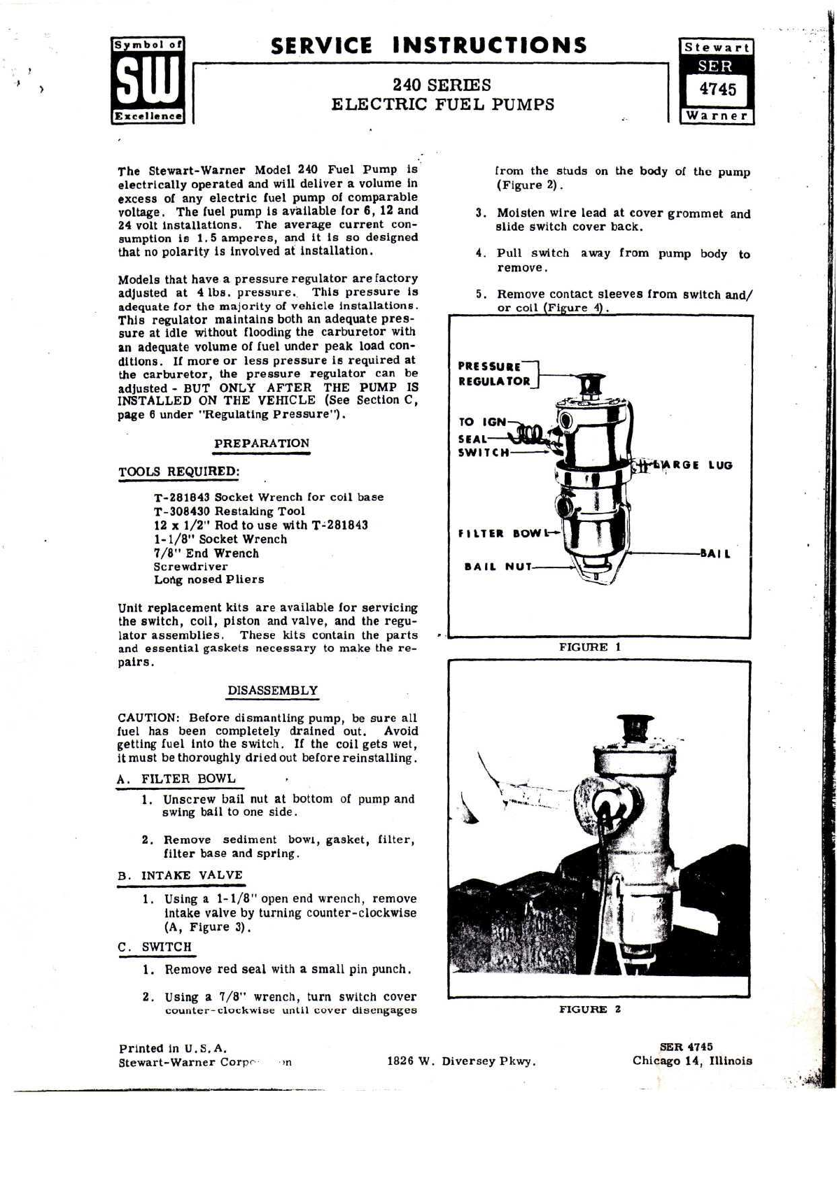
The
Stewart-Warner
Model
240
FuelPump
is
electrically
operated
and
will
deliver
a
volume
in
excess
ofany
electric
fuel
pump
of
comparable
voltage.
The
fuel
pump
is
available
for6,12and
24
volt
Installations.
The
average
current
con-
sumption
is
1.5
amperes,
andit
is
so
designed
that
no
polarity
is
involved
at
Installation.
Modelsthathave
a
pressure
regulator
are
factory
adjusted
at4
Ibs.
pressure.
This
pressure
is
adequate
forthe
majority
of
vehicle
installations.
This
regulator
maintainsboth
an
adequate
pres-
sure
at
idle
withoutflooding
the
carburetor
with
an
adequatevolume
of
fuel
under
peak
load
con-
ditions.
If
more
or
less
pressure
is
required
at
the
carburetor,
the
pressure
regulator
canbe
adjusted
- BUT
ONLYAFTER
THE
PUMP
IS
INSTALLED
ONTHE
VEHICLE
(See
Section
C,
page
6
under"Regulating
Pressure").
PREPARATION
TOOLSREQUIRED:
T-281843
SocketWrench
for
coil
base
T-308430
Restaking
Tool
12
x
1/2"
Rodtouse
withT-281843
1-1/8"
SocketWrench
7/8"
End
Wrench
Screwdriver
Long
nosed
Pliers
Unit
replacement
kits
are
available
for
servicing
the
switch,
coll,
piston
and
valve,
andthe
regu-
lator
assemblies.
These
kits
contain
the
parts
and
essential
gaskets
necessary
to
make
there-
pairs.
DISASSEMBLY
CAUTION:
Beforedismantlingpump,
be
sure
all
fuel
has
beencompletely
drained
out.
Avoid
getting
fuel
into
the
switch.
Ifthe
coil
gets
wet,
it
must
be
thoroughly
dried
out
before
reinstalling.
A.
FILTERBOWL
1.
Unscrewbail
nutat
bottom
of
pump
and
swingbail
toone
side.
2.
Removesedimentbowl,gasket,filter,
filter
base
and
spring.
B.
INTAKE
VALVE
1.
Using
a
1-1/8"
open
end
wrench,
remove
Intake
valve
by
turningcounter-clockwise
(A,
Figure
3).
C.
SWITCH
1.
Remove
red
seal
with
a
small
pin
punch.
2.
Using
a
7/8"
wrench,turnswitch
cover
counter-clockwise
until
coverdisengages
from
the
studs
onthe
body
ofthe
pump
(Figure
2).
3.
Moistenwirelead
at
cover
grommet
and
slide
switch
cover
back.
4.
Pull
switchawayfrompumpbody
to
remove.
5.
Removecontact
sleeves
fromswitch
and/
or
coil
(Figure
4).
PRE
SSURE
I
REGULATOR_T~
|ji/
_..^S
>ARGI
LUG
FILTER
BOWL-
BAIL
NUT
BAIL
FIGURE
1
FIGURE
2
Printed
in
U.S.A.
Stewart-Warner
Corpo
1826
W.
Diversey
Pkwy.
SER
4745
Chicago
14,
Illinois

(Symbol
of
SERVICE
INSTRUCTIONS
240
SERIESELECTRICFUELPUMP
SWITCH
KITNO.
426944
Stewart!
(A)
(B)
(C)(D)
oO
CONTENTS
OF
KIT
(A)
1-427879
Seal
(D)
2-425650Sleeve
(C)
1-425655Gasket(Small)
(D)
1-425660Gasket(Large)
(E)
1-425601Switch
&
Lead
Assem.
(F)
1-432975Bowl
Gasket
After
the
switch
has
beenremoved,
It
will
be
necessary
to
partiallydisassemble
the
pump
before
the
switch
canbe
replaced.
Failure
to
follow
theseInstructions
will
result
In
damaging
the
actuator
arm
bushing.Correct
procedure
Is
as
follows:
1.
Install
the
switchcontact
sleeves
onto
the
coll
terminals.
2.
Unscrew
ball
nutat
bottom
of
pump
and
swing
ball
toone
side.
3.
Remove
sediment
bowl,
gasket,filter,filter
base
and
spring.
4.
Using
a
suitablewrench,removeIntakevalve
assembly
by
turningcounter-clockwise.
5.
Trip
actuator
armof
switch
upward.
(Fig.
1).
Figure
1.
6.
With
finger
pressure
hold
piston
to
its
upper-
most
position,
then
release
pistonapproxi-
mately
1/8".
THIS
ISTHE
ONLY
POSITION
OFTHE
PISTON
THAT
THE
SWITCH
CAN
BE
REINSTALLED.
IMPORTANT:
Always
usenew
gaskets
and
seal
rings
during
reassembly.
7.
With
gaskets
In
place,
press
switch
Intopump
body
making
certain
the
switchcontactsengage
with
the
contact
sleeves.
Dueto
alignment
slot
on
switch,
It
can
only
be
Installedoneway.
8.
Replaceswitchcover
and
secure.
Note:
Vent
hole
In
covermustfacedownward.
9.Be
certain
the
"O"
ring
andthe
washer
are
In
place
atthe
protrudingportion
ofthe
piston
tube.
10.
Insertpowerspring
after
the
piston.Replace
Intake
valve,tighteningclockwiseuntil
itis
snug.Overtightening
will
cause
the
piston
tube
to
collapse.
When
properlyassembled
there
will
bea
space
between
the
valve
and
coll
base.
11.
After
inspection
or
cleaning
of
sediment
bowl,
assemblefilter
as
shown
In
Fig.
2.
Figure
2.
12.
Check
operation
of
pump
before
installation.
For
moredetailedinformation
see
SER-SW
4745
Printed
in
U.S.
A.
STEUJflRT-LUflRPER
CORPORflTIOR
1826
W.
DlverseyParkway
Chicago,
Illinois
60614
P.N.
434354
SER
4746
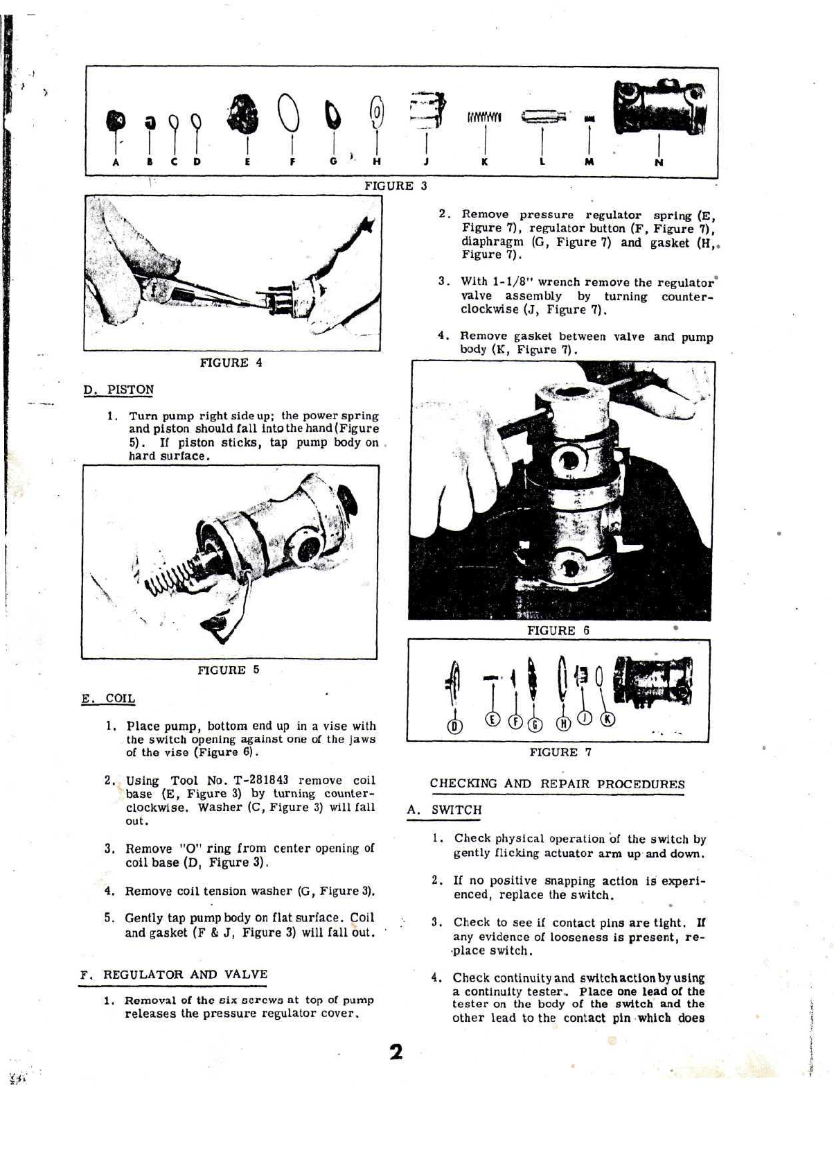
T
0
b
((
IWWWI
A
B
C D E F
G'H
M
FIGURE
3
FIGURE
4
D.
PISTON
1.
Turn
pump
right
side
up;
the
powerspring
and
pistonshouldfallinto
the
hand(Figure
5).
If
piston
sticks,
tap
pump
body
on
hardsurface.
\
FIGURE
5
E.
COIL
1.
Placepump,bottom
endupina
vise
with
the
switchopeningagainst
oneofthe
jaws
of
the
vise
(Figure
6).
2.
Using
Tool
No.
T-281843
removecoil
base
(E,
Figure
3)by
turning
counter-
clockwise.Washer
(C,
Figure
3)
will
fall
out.
3.
Remove
"O"
ring
from
center
opening
of
coil
base
(D,
Figure
3).
4.
Removecoiltensionwasher
(G,
Figure
3).
5.
Gently
tap
pump
body
on
flat
surface.
Coil
and
gasket
(F& J,
Figure
3)
will
fall
out.
•
F.
REGULATOR
AND
VALVE
1.
Removal
of
the
six
screws
attopof
pump
releases
the
pressure
regulator
cover.
2.
Remove
pressure
regulatorspring
(E,
Figure
7),
regulator
button
(F,
Figure
7),
diaphragm
(G,
Figure
7)and
gasket
(H,,
Figure
7).
3.
With
1-1/8"
wrench
remove
the
regulator"
valve
assembly
by
turningcounter-
clockwise
(J,
Figure
7).
4.
Removegasket
between
valve
and
pump
body
(K,
Figure
7).
FIGURE
6
f
T'.H'H
(D
cn
FIGURE
7
CHECKING
AND
REPAIR
PROCEDURES
A.
SWITCH
1.
Check
physical
operation
ofthe
switch
by
gently
flicking
actuator
armupand
down.
2.Ifno
positive
snapping
action
is
experi-
enced,
replace
the
switch.
3.
Check
toseeif
contactpins
are
tight.
If
any
evidence
of
looseness
is
present,
re-
•place
switch.
4.
Check
continuity
and
switch
action
by
using
a
continuity
tester.
Place
one
lead
ofthe
tester
onthe
body
ofthe
switch
andthe
other
lead
tothe
contact
pin
which
does

not
have
the
switchleadwireattached.
Flick
actuator
armofthe
switch,
circuit
should
indicate
open
and
closed
onthe
meter.
NOTE:
This
switch
isnot
serviceable,
andisto
be
replaced
asan
assembly.
.Use
Unit
Replacement
KitNo.
426944.
NOTE:
If
contact
sleeves
(A)are
damaged,
replace.
FIGURE
8
B.
INTAKE
VALVE
1.
This
unit
canbe
checked
by
placing
the
threadedportion
to
your
lips
and
forcing
air
into
the
valve.
2.Ifthe
valve
leaks,
theair
will
escape
and
must
be
replaced.
NOTE:
This
valve
isnot
serviceable
andistobe
replaced
asan
assembly.
Use
Unit
Re-
placement
KitNo.
426946.
C.
PISTON
1.
Inspect
bumper
spring.
The
minimum
measurement
ofthe
power
spring
ofa 6
volt
pump
is
1-21/32"
while
that
ofthe12
and
24
volt
pumpsmeasures
1-7/8"
(Fig-
ure
10).
FIG,
9
il
6v
12v+J4v
FIG.
10
FIG.
11
2.
Place
the
bumperspring
opening
ofthe
piston
tothe
lips
and
force
airtothe
pistoncheckvalve.
Ifair
escapes,
re-
place
the
piston.
3.
Light
score
marks
will
be
present
after
piston
has
been
in
useand
in
no
way
affects
the
performance
ofthe
pump.
The
normal
appearance
ofthe
piston
after
use
Is
shown
in
Figure
11.
Inspect
the
pistontube
for
nicks
or
scars.
A
tube
which
indicatesnormalwearwill
have
a
slight
ring
atthe
lower
end.
This
will
be
felt
by
running
the
finger
inside
the
tubeopening.
Check
whetherpistontube
is
properly
sealed
by
placingindexfinger
onendof
tube
and,
without
force,attempt
to
wiggle
(Figure
12).
Thereshould
beno
move-
ment
ofthe
pistontube.
IMPORTANT:
To
properly
rebuild
the
pump
and
Insure
against
leakage,
the
piston
tube
must
be
re-staked.
Use
Tool
No.
T-308430(Figure
13).
The
re-staking
toolconsists
oftwo
parts;
base
and
piston
tube
guide
anda
stakingpunch.
Touse
this
tool,
place
the
pump
casting
over
the
base.
The
pistontubeguide
will
auto-
matically
center
both
the
casting
andthe
pistontube.Place
the
restaking
punch
over
the
pistontube.Using
a
1-1/2pound
hammer,
strike
the
punch
sharply
oneor
two
blows.
FIGURE
12
FIGURE
13
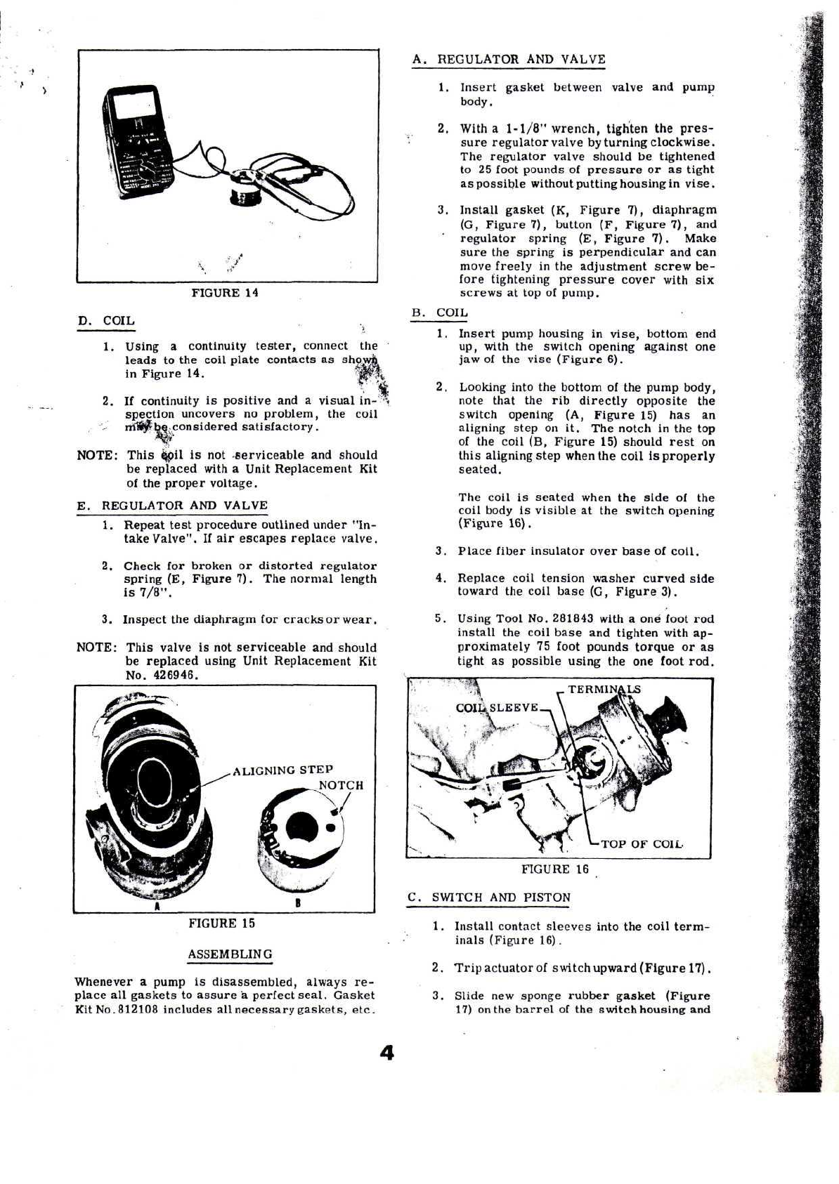
FIGURE
14
D.
COIL
the
1.
Using
a
continuity
tester,
connect
leads
tothe
coilplatecontacts
as
in
Figure
14.
2.If
continuity
is
positive
anda
visual
in-''
spectionuncovers
no
problem,
the
coil
ml^
bec
considered
satisfactory.
NOTE:
This
$pil
isnot
.serviceable
and
should
be
replaced
with
a
Unit
Replacement
Kit
of
the
propervoltage.
E.
REGULATOR
AND
VALVE
1.
Repeat
test
procedure
outlinedunder"In-
take
Valve".
Ifair
escapesreplace
valve.
2.
Check
for
broken
or
distortedregulator
spring
(E,
Figure?).
The
normallength
is
7/8".
3.
Inspect
the
diaphragm
for
cracks
or
wear.
NOTE:
Thisvalve
isnot
serviceable
and
should
be
replaced
using
Unit
Replacement
Kit
No.
426946.
ALIGNING
STEP
NOTCH
FIGURE
15
ASSEMBLING
Whenever
a
pump
is
disassembled,always
re-
place
all
gaskets
to
assure
a
perfect
seal.
Gasket
Kit
No.812108
includes
all
necessarygaskets,etc.
A.
REGULATOR
AND
VALVE
1.
Insertgasket
between
valve
and
pump
body.
2.
With
a
1-1/8"
wrench,tighten
the
pres-
sureregulatorvalve
by
turning
clockwise.
The
regulator
valve
should
be
tightened
to25
foot
pounds
of
pressure
oras
tight
as
possible
without
putting
housing
in
vise.
3.
Installgasket
(K,
Figure
7),
diaphragm
(G,
Figure
7),
button
(F,
Figure
7),and
regulatorspring
(E,
Figure
7).
Make
sure
the
spring
is
perpendicular
andcan
move
freely
inthe
adjustment
screw
be-
fore
tightening
pressure
cover
with
six
screws
attopof
pump.
B.
COIL
1.
Insert
pump
housing
in
vise,bottom
end
up,
with
the
switch
opening
against
one
jaw
ofthe
vise(Figure
6).
2.
Looking
into
the
bottom
ofthe
pump
body,
note
that
therib
directlyopposite
the
switch
opening
(A,
Figure
15)hasan
aligning
step
onit.The
notch
inthetop
of
the
coil
(B,
Figure
15)
should
rest
on
this
aligning
step
when
the
coil
is
properly
seated.
The
coil
is
seated
when
the
side
ofthe
coil
body
is
visible
atthe
switch
opening
(Figure
16).
3.
Place
fiberinsulatorover
base
of
coil.
4.
Replacecoiltensionwashercurvedside
toward
the
coil
base
(G,
Figure
3).
5.
Using
Tool
No.
281843
with
a one
foot
rod
install
the
coilbase
and
tighten
with
ap-
proximately
75
foot
poundstorque
oras
tight
as
possibleusing
theone
foot
rod.
TOPOF
COIL
FIGURE
16
C.
SWITCH
AND
PISTON
1.
Install
contact
sleeves
into
the
coil
term-
inals
(Figure
16).
2.
Trip
actuator
of
switch
upward(Figure
17).
3.
Slide
new
sponge
rubber
gasket
(Figure
17)
on
the
barrel
ofthe
switchhousing
and
sealinggasket
on
otherend.
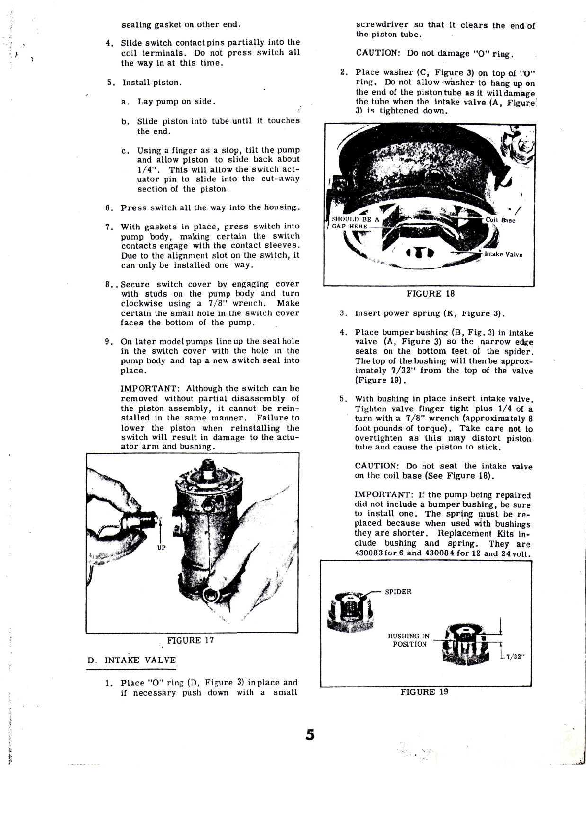
4.
Slideswitchcontactpinspartiallyinto
the
coilterminals.
Donot
press
switch
all
thewayinat
thistime.
5.
Installpiston.
a.
Lay
pump
on
side.
b.
Slidepistonintotubeuntil
it
touches
the
end.
c.
Using
a
finger
asa
stop,tilt
the
pump
and
allowpiston
to
slidebackabout
1/4".
Thiswillallow
the
switchact-
uator
pinto
slide
into
the
cut-away
section
of
the
piston.
6.
Press
switch
alltheway
into
the
housing.
7.
With
gaskets
in
place,
press
switchinto
pumpbody,making
certain
the
switch
contactsengage
with
the
contact
sleeves.
Due
tothe
alignment
slot
onthe
switch,
it
can
only
be
installed
one
way.
8..
Secureswitch
cover
by
engagingcover
with
studs
onthe
pump
body
and
turn
clockwiseusing
a
7/8"wrench.Make
certain
the
smallhole
inthe
switchcover
faces
the
bottom
ofthe
pump.
9.On
later
modelpumpslineup
the
seal
hole
in
the
switchcover
with
the
hole
inthe
pump
body
andtapa new
switch
seal
into
place.
IMPORTANT:
Although
the
switch
canbe
removed
without
partialdisassembly
of
the
pistonassembly,
it
cannot
be
rein-
stalled
inthe
samemanner.
Failure
to
lower
the
piston
when
reinstalling
the
switch
willresult
in
damage
tothe
actu-
ator
armand
bushing.
FIGURE
17
D.
INTAKE
VALVE
1.
Place
"O"
ring
(D,
Figure
3)in
place
and
if
necessarypush
down
with
a
small
screwdriver
so
that
it
clears
theendof
the
pistontube.
CAUTION:
Donot
damage
"O"
ring.
Place
washer
(C,
Figure
3)ontop
of
"O"
ring.
Donot
allow'washer
to
hang
upon
the
endofthe
pistontube
asit
willdamage
the
tube
when
the
intakevalve
(A,
Figure
31
Is
tighteneddown.
FIGURE
18
3.
Insertpower
spring
(K,
Figure
3).
4.
Place
bumper
bushing
(B,
Fig.
3)in
intake
valve
(A,
Figure
3)sothe
narrowedge
seats
onthe
bottomfeet
ofthe
spider.
Thetopofthe
bushingwill
then
be
approx-
imately7/32"from
thetopofthe
valve
(Figur°
19).
5.
With
bushing
in
place
insert
intakevalve.
Tighten
valvefingertightplus
1/4ofa
turn
with
a
7/8"wrench(approximately
8
foot
pounds
of
torque).
Take
care
notto
overtighten
as
this
may
distort
piston
tube
and
cause
the
piston
to
stick.
CAUTION:
Donot
seat
the
intakevalve
on
the
coil
base
(See
Figure
18).
IMPORTANT:
Ifthe
pumpbeing
repaired
did
not
include
a
bumperbushing,
be
sure
to
installone.
The
spring
must
bere-
placed
because
whenusedwithbushings
they
are
shorter.
ReplacementKits
in-
cludebushing
and
spring.
They
are
430083
for6 and
430084
for12and24
volt.
SPIDER
BUSHING
IN
POSITION
7/32"
FIGURE
19
FIGURE
20
E.
FILTER
BOWL
ASSEMBLY
1.
Afterinspection
or
cleaning
of
sediment
bowl,
always
usea new
bowl
gasket(Fig-
ure
20).
2.
Place
spring
inside
sedimentbowl(Fig-
ure
20).
3.
Place
filter
base
ontopof
spring
as
shown
(Figure
20).
4.
Place
filter
ontopof
filter
base
(Figure
20).
5.
Place
gasket
ontopof
sedimentbowl
(Figure
20.
PERFORMANCE
A.
EstablishingStandardLoad
Test
1.
All
tests
should
be
madeusing
5/16"O.D.
tubing
on
both
the
inlet
and
discharge
side
of
the
pump.
The
pump
shall
also
be
tested
ina
verticalposition
with
the
inlet
part
approximately
12"andnot
exceeding
24"
above
the
level
ofthe
fuel
supply.
Thesechecks
canbe
madeeither
onthe
vehicle
orata
bench
test.
B.
Pressure
1.
Place
fuel
pump
ona
650-BTestFixture
(Figure
22)or
other
suitable
fixture
if
available.
With
the
lower
or
intakepart
connected
to
a
fuel
supply,
connect
a
pres-
sure
gauge
anda
bleeder
valve
tothe
dis-
charge
ortop
part
ofthe
pump.
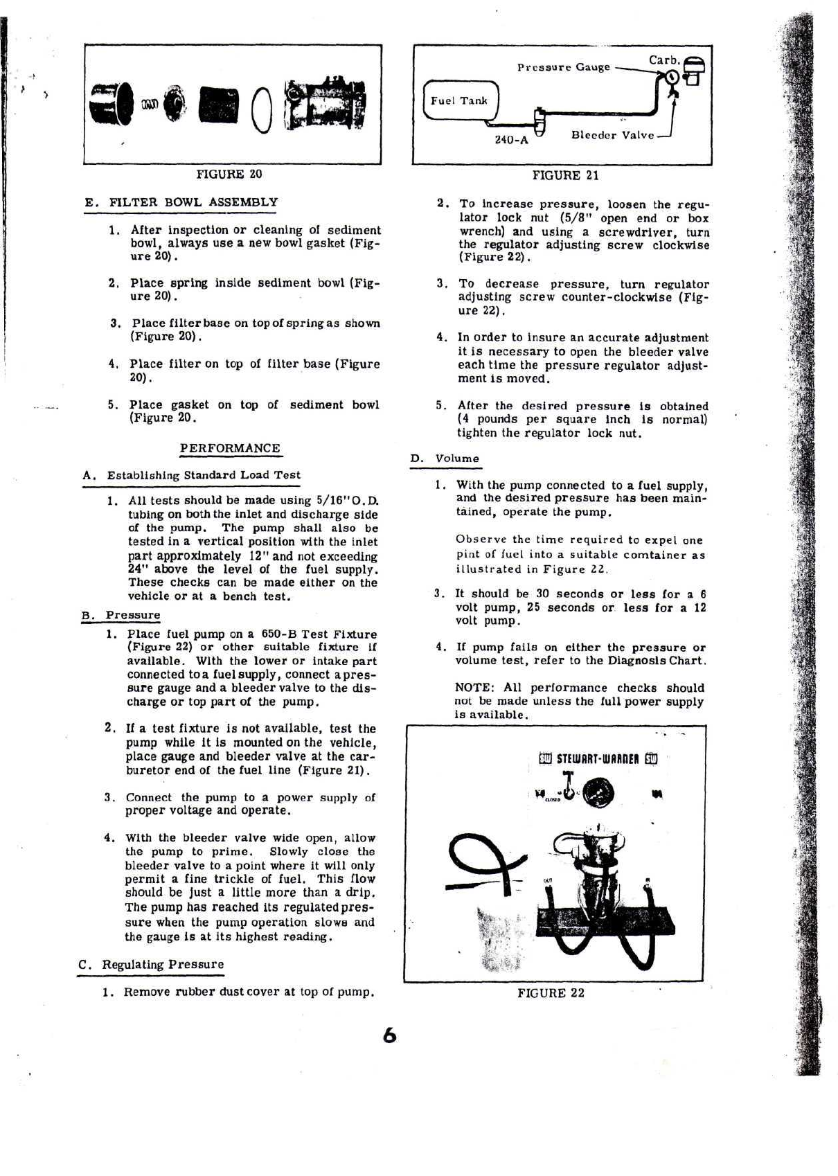
2.
Ifa
test
fixture
isnot
available,
test
the
pump
while
itis
mounted
onthe
vehicle,
placegauge
and
bleedervalve
atthe
car-
buretor
endofthe
fuel
line(Figure
21).
3.
Connect
the
pump
toa
power
supply
of
propervoltage
and
operate.
4.
With
the
bleedervalve
wide
open,allow
the
pump
to
prime.
Slowly
close
the
bleedervalve
toa
pointwhere
it
will
only
permit
a
fine
trickle
of
fuel.
This
flow
should
be
just
a
littlemorethan
a
drip.
The
pump
has
reached
its
regulated
pres-
sure
when
the
pump
operation
slows
and
the
gauge
Is
atits
highestreading.
C.
Regulating
Pressure
1.
Removerubberdustcover
attopof
pump.
240-A
Bleeder
Valve
-
FIGURE
21
2.To
increase
pressure,
loosen
the
regu-
lator
lock
nut
(5/8"open
endorbox
wrench)
and
using
a
screwdriver,
turn
the
regulatoradjustingscrewclockwise
(Figure
22).
3.
To
decrease
pressure,
turnregulator
adjusting
screwcounter-clockwise
(Fig-
ure
22).
4.In
order
to
insure
an
accurateadjustment
it
is
necessary
to
open
the
bleedervalve
each
time
the
pressure
regulatoradjust-
ment
is
moved.
5.
After
the
desired
pressure
is
obtained
(4
pounds
per
square
inch
is
normal)
tighten
the
regulatorlocknut.
D.
Volume
1.
With
the
pump
connected
toa
fuel
supply,
and
the
desired
pressure
has
beenmain-
tained,operate
the
pump.
Observe
the
time
required
to
expel
one
pint
of
fuel
into
a
suitable
comtainer
as
illustrated
in
Figure
22.
3.It
should
be30
seconds
or
less
fora 6
volt
pump,
25
seconds
or
less
fora 12
volt
pump.
4.If
pump
fails
on
either
the
pressure
or
volume
test,
refer
tothe
Diagnosis
Chart.
NOTE:
All
performancechecksshould
not
be
madeunless
the
full
powersupply
is
available.
FIGURE
22

CONDITION
PROBABLE
CAUSE
REMEDY
1.
Pump
stalls
andishot
to
touch
or
pump
operates
intermittently,
delivers
little
orno
fuel.
A.
Poorground
or
wirecon-
nections
B.
Wronggaugewire
C.
Damagedswitch
D.
Damaged
piston
tube
binding
onthe
piston
A.
Make
sure
pump
is
properly
grounded...
B.
UseNo.10
gaugewire
C.
Replaceswitch
D.
Replace
pumpbody.
2.
Pumpdoes
not
operate
A.
Open
circuit
in
switch
B.
Open
circuit
in
coil
C.
No
ground
or
break
in
wiring
A.
Replaceswitch
B.
Replacecoil
C.
Connectground
wire.
Solder
all
wireconnections,
replacing
broken
or
worn
wiring.
3.
Pump
operates
inter-
mittently
or
delivers
little
orno
fuel
A.Bad
connection
of
wire
lead.
B.Bad
groundconnection
C.
Intakelineclogged
D.
SedimentBowlclogged
E.
Broken
or
damagedspring
in
contactswitch
F.
Nylon
bushingpushedback
on
switchactuating
arm
G.
Damagedpistontube
binding
on
piston
A.
Check
all
pumpwiring
and
connections
B.
Using
a
jumperwire,hold
one
end
to
pump
body
and
ground
the
other.
If
pump
operates,
make
a
permanentground
connection
C.
Disconnect
line
from
pump
inlet
port.
If
pump
operates,
removeintakeline,clean
and
drain
fuel
tank.
D.
Removesedimentbowl
and
filter.
Cleanthoroughly
and
replace
using
new
bowl
gasket
E.
Removeswitch
and
check
physical
operation.
F.
Replaceswitch
G.
Replace
pump
body.
Pump
races
or
delivers
little
orno
fuel
A.
Fueltankempty
B.
Leak
in
intakeline
C.
Leakaroundsediment
bowl
D.
Vapor
in
lines
E.
Faulty
or
dirtyintakevalve
F.
Filter
clogged
.
A.
Check
fuel
supply
B.
Checkline
and
fittings
for
leak
at
intake
port.
Replacefittings
using
a
sealingcompound
C.
Replacegasket
and
tighten
bail
nut
D.
See
that
pump
is
mountedaway
from
extreme
heat.
E.
Inspectintake
and
pistoncheck
valves.
See
PistonAssembly,
page
3.
Replace
as
necessary.
F.
Removesedimentbowl
and
clean
parts
thoroughly.
Re-
using
new
how!
gasket
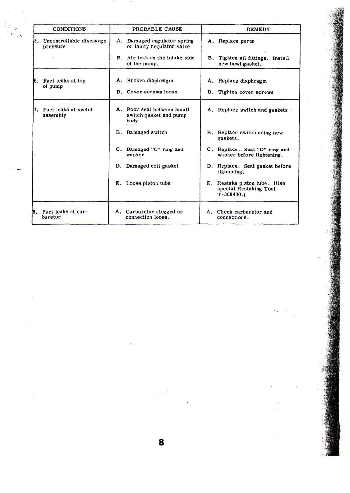
CONDITIONS
5.
Uncontrollable
discharge
pressure
-
6.
Fuelleaks
attop
of
pump
7.
Fuelleaks
at
switch
assembly
8.
Fuel
leaks
at
car-
buretor
PROBABLE
CAUSE
A.
Damaged
regulator
spring
or
faulty
regulatorvalve
B.Air
leak
onthe
intakeside
of
the
pump.
A.
Brokendiaphragm
B.
Coverscrews
loose
A.
Poor
seal
between
small
switch
gasket
and
pump
body
B.
Damagedswitch
C.
Damaged
"O"
ring
and
washer
D.
Damagedcoilgasket
E.
Loose
piston
tube
A.
Carburetorclogged
or
connection
loose.
REMEDY
A.
Replace
parts
B.
Tighten
all
fittings.
Install
new
bowl
gasket.
A.
Replacediaphragm
B.
Tightencover
screws
A.
Replaceswitch
and
gaskets
•
B.
Replaceswitchusing
new
gaskets.
C.
Replace..
Seat
"O"
ring
and
washerbefore
tightening.
D.
Replace.Seatgasketbefore
tightening.
E.
Restakepistontube.(Use
special
Restaking
Tool
T-308430.)
A.
Checkcarburetor
and
connections.
8

SYMBOL
OF
SERVICE
INSTRUCTIONS
STEWART
EXCELLENCE
240
SERIES
ELECTRIC
FUEL
PUMPS
REGULATOR
Kir
NO.
426945
^DIAPHRAGM
*
VALVE
ASSEMBLY
*
BODY
GASKET
*VALVE
ASSEMBLY
GASKET
WARNER
REGULATOR
SPRING
PUMP
BODY
DISTRIBUTION
PLATE
„
-'(6)
COVER
ADJUSTMENT
PUMP
BODY
COVER
^J
PULSE
CHAMBER
LOCKNUT
1
*
INDICATES
PARTS
CONTAINED
IN
KIT.
KIT
CONTENTS
(1)
425654
Valve
Gasket
(1)
425645
Diaphragm
(1)
425626
Valve
Assembly
(1)
425646
Regulator
Spring
(1)
425656
Body
Gasket
CAUTION:
//
adjustment
screw
is
removed
or
loosened',
the
pump
will
require
rccalibration
for
proper pressure delivery.
DISASSEMBLY
1.
Place
fuel
pump
ina
vice
inthe
uprightposition
and
secure.
2.
Remove
thesix(6)
screws
on
cover
of
pump.
NOTE:
While
removing
the
screws hold cover
down
with
hand.
The
cover
is
under
pressure
due to the
adjustment
screw
and
regulator
spring.
3,
Slowlyremovecover,regulatorspring
and
distri-
bution
plate.
4.
Remove
diaphragm
and
body
gasket.
5.
Using
a
wrench
(box
endor
socket),
turn
counter-
clockwise
to
remove
the
valve
assembly
and
valve
assembly
gasket.
CAUTION:
Donot
nick,
scratch
ormar
body
machined
surface
for
gasket
425656.
This will
prevent
leaks.
NOTE:
Before
assembly
clean
the
surfaces
ofthe
pump
body
to
insure
proper
seating
of
gaskets. This
will reduce
the
possibilities
of
leaks.
1.
Place
new
valve
gasket
onnew
valve
assembly.
2.
Insert
new
valve
assembly
and
gasket
intobody
of
pump.Turnclockwise
with
suitable
wrench(box
end
or
socket)
until
firmly
seated.
3.
Place
new
body
gasket
and
diaphragm
on
body
of
pump.Align
the
holes
in
gasket
and
diaphragm
to
those
in
pumpbody.
ASSEMBLY
4.
Center
distributionplate
on
diaphragm.
NOTE:
Pilot
on
distribution
plate
must
beontop
to
align
with
regulator spring.
5.
Place
regulator
spring
on
distribution
plate
(over
pilot).
6.
Replace
the
cover
and
position
the
holes
in
cover
to
align
with
holes
in
body
of
pump.
NOTE:
Pressure
may
have
to
be
applied
on
cover
to
start
the
screws back
in to
pump
body.
If
so
hold
cover
down
against
pump
body
and
insert screws,
then
tighten screws.
Printed
in
U.S.A.
FOR
FURTHERSERVICE,CONTACTYOURLOCAL
STEWART-WARNER
DISTRIBUTION
CENTER
STEUJflRT-LURRnEB
CORPORRTIOd
1826
W.
Diversey
Parkway
Chicago,
Illinois60614
P.N.434355
SER
4747
Popular Water Pump manuals by other brands

Agilent Technologies
Agilent Technologies DS40M user manual

Goulds
Goulds J5 instruction manual

Xylem
Xylem Rule 27SA instruction manual

Sealey
Sealey WPW9355 instructions

NEPTUN classic
NEPTUN classic NCGP-E 70 Original operating instructions

Grundfos
Grundfos DWK Series Installation and operating instructions

Tunze
Tunze Osmolator 3155 Instructions for use

Pentair
Pentair FAIRBANKS HIJHUIS 5800 Instruction and maintenance manual

Renkforce
Renkforce 2302374 operating instructions

Sicce
Sicce Syncra Nano instructions

Pfeiffer Vacuum
Pfeiffer Vacuum HIPACE 350 operating instructions

aquate
aquate 1350 Series Installation and operating manual


