STI solar 5500 User manual
© 2006 STI Group, Inc.
For further information, including parts, warranty repair
or general inquiries, please contact the STI Group, Inc. at:
Intellectual Property
This product is covered by one or more international and US patents pending.
All logos, designs and colors are copyrights and trademarks of STI Group, Inc.
All rights reserved 2006
Please register your product online at our website:
www.stigroupinc.com/registration
USA Corporate Office
Tel: 847.918.8558
Address: 1203 Loyola Drive •Libertyville, IL 60048
Email: [email protected]
Website: www.stigroupinc.com
STI Group Inc. Locations:
CHICAGO LOS ANGELES ATLANTA SHENZHEN, CHINA
Model 5500
Solar Motion Sensor
Security Light
Powerful 10 Watt Halogen Security Light
5500 manual 10/6/06 9:03 AM Page 2
SOLAR MOTION SENSOR SECURITY LIGHT
Instruction Manual Model 5500
SOLAR MOTION SENSOR SECURITY LIGHT
Instruction Manual Model 5500
CONTENTS
1. Introduction
2. Security instructions
3. Components
4. Mounting Instructions
5. Initial Charging Set-up
6. Understanding the Motion Sensor Controls
7. Adjusting Lamp Housing
8. Replacing Bulb & Battery
9. General Electrical and Safety Warnings
10. Cleaning
11. Storage
12. Troubleshooting
13. Technical Data
14. Spare Parts
15. One Year Limited Warranty
These instructions relate ONLY to this Solar Motion Sensor
Set and contain important information for using the
product for the first time. Please keep these instructions
for later reference. They should always accompany the
product in the event of transfer to a new user.
1. INTRODUCTION
Thank you for purchasing this Solar Motion Sensor Security Light.
You have purchased a product that complies with the latest
and most up-to-date solar technology available.
This product complies with the European and National Standards.
The relevant certificates of conformity are held by STI Group.
To preserve these standards and in order to maintain safety you
should adhere to the instructions for use detailed in this manual.
2. SECURITY INSTRUCTIONS
In the event of any problems arising or damage occurring as a
result of misuse the manufacturers warranty will be deemed
cancelled. The manufacturer is not responsible for any claims or
damages arising from the misuse of this product.
For safety reasons and in order to maintain standards (CE) you
are prohibited from altering or changing any component in this
Solar Motion Sensor Security Light.
Please follow the instructions very carefully.
For commercial applications due care and attention must be paid
to the Health and Safety Standards in your jurisdiction.
Figure A
Figure B
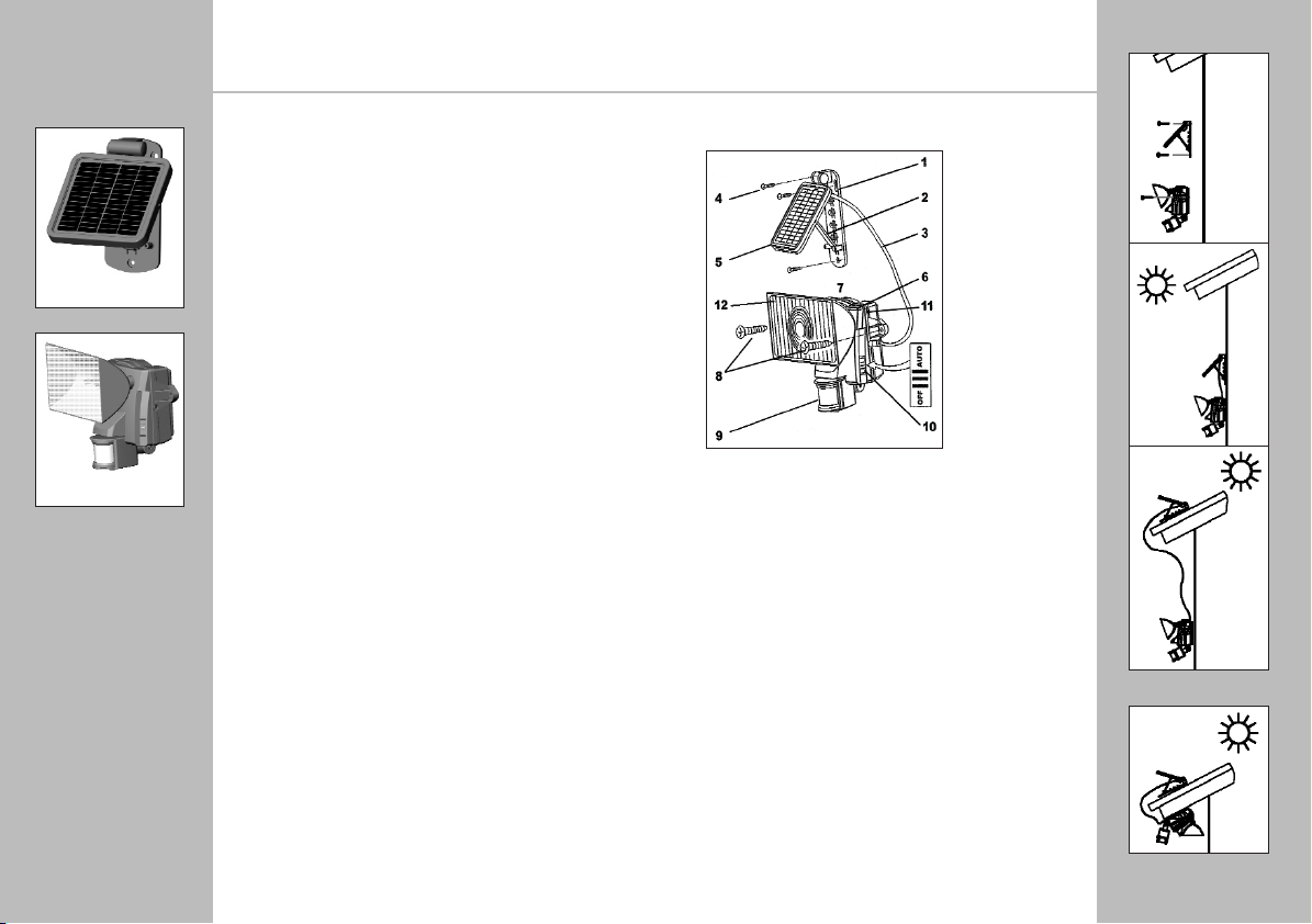
3. COMPONENTS
4. MOUNTING INSTRUCTIONS
1. Mounting Bracket
2. Adjustment
Support
3. Power Cable
4. Solar Cell Mounting
Screws (x3)
5. Solar Cell
6. Main Battery Unit
7. Main Unit
8. Mounting Screws (x2)
9. PIR Sensor
10. AUTO / OFF
Switch
11. AC-DC Adaptor
Interface (requires
9VDC/500mA output
adaptor (not included)
12. Transparent
Light Cover
HOW TO DETERMINE WHERE TO MOUNT
YOUR SOLAR MOTION SENSOR SECURITY LIGHT
Note: In the FIGURE B position, it is important not to let rain
enter the main unit. Make sure it is mounted in a covered area.
Please note that: DIRECT SUNLIGHT is important for the
operation of SOLAR MOTION SENSOR SECURITY LIGHT. The
more direct sunlight the solar cell receives in daytime, the longer
the light will operate. (Else, you have to charge it through the
Adaptor hole on the main body’s side)
Main Unit: The main unit contains the lamp (10Watt/6V G5.3
halogen bulb), motion sensor and battery (sealed Lead-Acid
Rechargeable battery, 6V, 4Ah). When determining where to
mount this unit, consider that the motion sensor has a detection
scope of around 39 feet (in front of the light) to 26 feet (around
the light). See FIGURE C on the next page. Sensor has a
horizontal field of vision of 180°. To mount the unit vertically as a
security light, attach the unit to a solid surface as shown in FIGURE
A. To mount the unit horizontally as convenience lighting, attach
the unit as shown in FIGURE B. Use the two wood/ sheet metal
screws provided in the package.
Solar Cell: The solar cell is the main power source for the
SOLAR MOTION SENSOR SECURITY LIGHT. It converts the
sunlight’s energy into electricity that charges the battery in main
unit. It requires DIRECT SUNLIGHT onto the surface of solar cell
for as long as possible during the daytime.
SOUTH
SOUTH
SOUTH
Solar Panel Unit
Lighting/Sensor Unit
5500 manual 10/6/06 9:03 AM Page 4

SOLAR MOTION SENSOR SECURITY LIGHT
Instruction Manual Model 5500
SOLAR MOTION SENSOR SECURITY LIGHT
Instruction Manual Model 5500
Use the three wood/sheet metal screws provided in the package
(#4 on parts list) to mount the solar cell unit onto a solid
surface. Make sure it is mounted fixed into the solid surface.
You can adjust the angle of the solar cell by moving the
adjustment bracket to the appropriate hook on the
mounting base. It should face as much DIRECT SUNLIGHT as
possible during the daytime.
At last route the solar cell’s power cord to the main unit and
plug it into the side hole for solar cell. Additionally, the side hole
for adaptor is for the secondary charging during raining season.
Important: if the main unit is mounted horizontally, it must
be mounted in a covered area so rain water can not get into
the unit through the exposed vents.
5. INITIAL CHARGING SET-UP
After you successfully installed your SOLAR MOTION SENSOR
SECURITY LIGHT, you are almost ready for carefree operation
with a few final steps:
Initial 3-days Charge:
On the main unit there is a slide switch with 2 positions:
• OFF • AUTO
AUTO - Position for normal operation
OFF - Position for delivery or long periods of non-use
Position for initial 3-day charge before first use.
Then, turn the slide switch to OFF position. The solar cell will
charge the battery without activating the unit. Leave the switch
in this position for 3 sunny days to ensure that the battery has a
full charge for motion sensor adjustment and normal operation.
6. UNDERSTANDING THE
MOTION SENSOR CONTROLS
After the initial 3-day charge, turn the switch to AUTO position.
In the motion sensor the following 3 specifics TIME / SENS /
LUX are pre-set in factory.
TIME - Duration time of the light to run after motion is
detected in the field, the duration time is set to 30 seconds.
On a fully charged battery, it can light up to 300
illuminations of 30 seconds each. Note: Once the light is
activated by the PIR sensor, any subsequent detection will
restart the timed period again from the beginning.
Vertical Mounting
Set-up
Horizontal Mounting
Set-up
Slide Switch
AC-DC Adaptor Interface.
Requires 9VDC/500mA
output adaptor
(not included).
SENS - The infra-red sensor’s detection range is preset to
detect movement from 26 to 39 feet away. This can be affected
by environmental temperature. The lower environmental
temperature and humidity, the more sensitive the PIR sensor.
Refer to FIGURE C for detection range.
LUX - The Lux control module has a built-in sensing device
(photocell) that detects daylight and darkness. The control
level is pre-set to 30 LUX, which denotes the dawn or dust
environmental level. When the environment is darker than 30
LUX, the sensor will start to work.
Walking test:
Point the motion sensor to facing the area you want to detect
motion in. Walking slowly in its detection area when it is
evening or when the environment is dark, the built-in infra-red
sensor detects movement by measuring the radiation given off
by the human body and then turns on the light. Test the
coverage of the area by walking around slowly until the light
does not switch on.
7. ADJUSTING LAMP HOUSING
Point the lamp housing facing the area you wish to illuminate.
8. REPLACING BULB & BATTERY
Caution: When replacing the bulb or battery, the slide switch
on the main unit must be in the OFF position.
Bulb Replacement: Depending on the amount of use, the
bulb in your SOLAR MOTION SENSOR SECURITY LIGHT is
designed to have an average life of about one year. When it
becomes necessary to replace the bulb, you can obtain a
replacement from location agent. The old bulb can be easily
replaced by popping the transparent light cover (#8 in parts
list) off with a screwdriver (there is a slot at one end of the
cover) and pulling the bulb from its base. Reverse this
procedure with the new bulb to reassemble.
IMPORTANT: The bulb will be hot when the light is on, please let
the bulb cool when replacing the bulb. Be extremely careful when
handing the bulb, especially if it is broken. Also, do not touch the
bulb with bare hands / fingers as this will shorten bulb life.)
Battery Replacement:
The battery in your SOLAR MOTION SENSOR SECURITY LIGHT
is designed to last for about 3 years. When it becomes
necessary to replace the battery, you can obtain a replacement
from your local distributor or STI Group.
Figure C
SENSOR
DETECTION RANGE
26 FT.
39
FT.
5500 manual 10/6/06 9:03 AM Page 6
SOLAR MOTION SENSOR SECURITY LIGHT
Instruction Manual Model 5500
SOLAR MOTION SENSOR SECURITY LIGHT
Instruction Manual Model 5500
12. TROUBLESHOOTING
Light does not switch on in darkness.
• Check whether the switch is on AUTO position.
• Check the motion sensor is positioned to detect movement.
• Check the solor module is correctly angled to pick-up enough sun.
• Check the bulb is not broken or out of its socket.
• Low battery - charge for 3 sunny days with switch in OFF position.
• Replace the bulb.
Light is not as bright as normal.
• Low battery - charge for 3 sunny days with switch in OFF position.
• Replace the bulb.
13. TECHNICAL DATA
Operation voltage: 6 Volt /4 Amp Hour
Solar module: 1.3 watts. 4.75" x 4.75"panel
Light source: 10 Watt / 6V G5.3 Halogen Lamp
Battery pack: 6V, 4AH Sealed Lead-Acid
Rechargeable Battery
Battery operation capacity: Up to 300 illuminations at 30 sec.
14. SPARE PARTS
Solar panel: Item No. SP5500
Halogen light: Item No. HL5500
Battery pack: Item No. BP5500
15. ONE YEAR LIMITED WARRANTY
Please register your product within 7 days at:
www.stigroupinc.com/registration
If within 12 months from the date of purchase this product fails
due to a defect in material or workmanship. STI Group will replace
or repair it free of charge. You will need to provide proof of
purchase and you may be required to send in the solar power
station to the STI Group repair center for warranty.
The warranty does not apply to:
Damage caused by accidents, abuse, poor handling, or normal
wear and tear. Products which have been subject to unauthorized
repair or modification. Batteries are a normal wear item and need
to be replaced periodically. For further information please contact
your nearest service centre detailed on the last page of this
instruction manual.
The old battery can be replaced by first removing the unit
from its mounting surface. Then remove the screws on the
back of the main unit which hold the halves together.
Carefully unplug the positive and negative battery leads and
unscrew the screws holding the battery retainer in place.
Carefully remove the battery from its compartment and
replace by reversing this procedure.
Caution: Make sure the (+) and (-) leads are attached correctly
to the appropriate (+) and (-) battery terminals. Serious damage
to the unit may result if they are connected backwards.
It is important to dispose of the battery in an environmentally
conscious manner. Dispose of according to applicable
governmental regulations. Recyclable.
9. GENERAL ELECTRICAL
AND SAFETY WARNINGS
1) The AUTO/OFF switch on the main unit must be in the OFF
position when changing the bulb or the battery.
2) Do not cut the solar cell wire. Discontinue use if the wire
becomes frayed or broken.
3) Do not immerse components in liquid.
4) Do not use any other charge than the single solar charging
panel provided with the SOLAR MOTION SENSOR SECURITY
LIGHT. This may result in injury or damage to the light and voids
any warranty.
5) Position so that the cord is securely fastened and will not
result in a hazard (such as tripping).
6) When changing the bulb or battery, be careful of any sharp
edges that could cut you or the wires. Do not pull on wires.
10. CLEANING
It is important that the solar panel is kept free of dirt and
debris. A dirty solar panel will not allow the battery to fully
charge and this will shorten the life of battery and cause the
light to malfunction.
11. STORAGE
If you wish to store your light indoors for more than two or
three days, follow these steps to prevent damage to battery:
1) Turn the switch to OFF position
2) Store the light and solar panel where it can receive some
sunlight or room light each day. The battery needs light to
maintain a charge during storage
3) During prolonged storage, unit must be fully charge once
every four months, for best performance, do not store for
prolonged periods.
5500 manual 10/6/06 9:03 AM Page 8
Table of contents
Popular Floodlight manuals by other brands


Performance In Lighting
Performance In Lighting SQUARE PRO quick start guide

GoodHome
GoodHome Summerside ASL1027-I manual

Elation
Elation EVC MH LED User instructions

lumishore
lumishore Flood Light 4 installation manual

NightSearcher
NightSearcher Solaris Pro-X user manual

Acclaim Lighting
Acclaim Lighting Dyna Accent user guide


