— 3 —
IMPORTANT NOTICE
Information and specifications are subject to change without notice.
This product has been tested and complies with the specifications for a Class B digital device, pursuant to Part
15oftheFCCRules.
These limits are designed to provide reasonable protection against harmful interference in a residential
installation.Thisequipmentgenerates,usesandcanradiateradiofrequencyenergyand,ifnotinstalledand
used according to the instructions, may cause harmful interference to radio communications. However, there
isnoguaranteethatinterferencewillnotoccurinaparticularinstallation.Ifthisequipmentdoescauseharmful
interferencetoradioortelevisionreception,whichisfoundbyturningtheequipmentoffandon,theuseris
encouragedtotrytocorrecttheinterferencebyoneormoreofthefollowingmeasures:
- Reorient or relocate the receiving antenna
-Increasetheseparationbetweentheequipmentordevices
-Connecttheequipmenttoanoutletotherthanthereceiver’s
-Consultadealeroranexperiencedradio/TVtechnicianforassistance
Operationissubjecttothefollowingtwoconditions:(1)thisdevicemaynotcauseinterference,and(2)
this device must accept any interference, including interference that may cause undesired operation of the
device. Changes or modifications not expressly approved by Safety Technology International, Inc. could void
yourauthoritytooperatethisequipment.Toreducepotentialradiointerferencetootherusers,theantenna
typeanditsgainshouldbesochosenthattheequivalentisotopicallyradiatedpower(e.i.r.p.)isnotmorethan
that permitted for successful communication. This product meets the applicable Industry Canada technical
specications.Leprésentmaterielestconformeauxspecicationstechniquesapplicablesd’IndustrieCanada.
FCCID:U5X-RE324IC:8310A-RE324
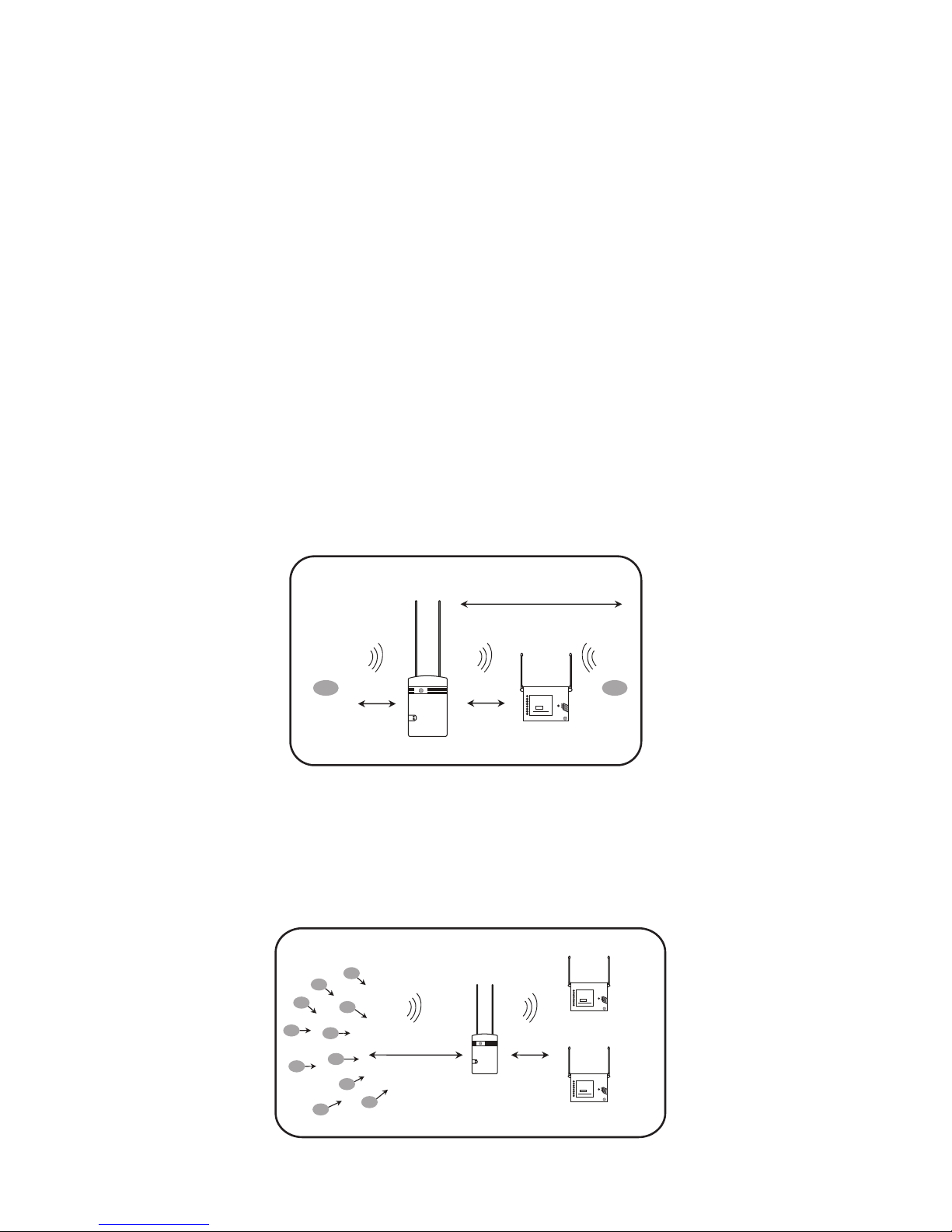
INSTALLATION GUIDE
The REPEATER is intended to be mounted indoors or in a waterproof environment. Review
the APPLICATIONS GUIDE for suggested setups.
1. Press the cover latch to remove top cover (do not lose tamper switch spring).
2. RemovethePCBfrombottomcover.
Usingthekeyholesonthebottomcoverasatemplate,markthetopandbottommountingholes.Locatethe
hole at least 1 foot away from the closest obstruction above.
3. Drill3/16”holes.
4. Insert wall anchors, screws and washers (provided) and tighten to 1/8” gap.
5. TURNOFFPOWERSUPPLY.Routepowersupplywiresfromtheside(recommended)orholefromtheback.
a.Sideinstallation–routewiresthroughrightwireguideandthenleftwireguide.Removeknockoutonthe
top cover.
b.Rearinstallation–runwiresthroughbackwireguideandthenleftwireguide.
6. Placebottomcoverkeyholesontoscrewsandorientdevicevertical.
7. Tightenscrews.
8. On the PCB, insert the antennas into the outer antenna terminals marked “ANTENNA.” Tighten the antenna
terminal screws.
9. SnapPCBintobottomcoversotheantennasareontheplasticstands.
10. Remove the battery tab. The red LED blinks when the batteries are installed. If LED does not blink, press
and release the tamper switch. If LED still does not blink, replace batteries.
11 .Insert12VoltACorDCpowersupplyleadsintotheterminalsmarked“AC/DC12V.”Thepositiveand
negativeterminalshaveinterchangeablepolarity.Theymaybeorientedeither+/-or-/+.
12.Turnonthepowersupply.ThegreenLEDturnson.IftheredLEDison,replacethe3AAAAlkaline
batteries.
13. (If desired) Program the REPEATER and/or the sensors into the receiver (follow the receiver programming
instructions).ThereceivercanmonitortheREPEATER’Ssupervisionandtroublesignalswhenenrolled.
To manually send a REPEATER signal, press and release the tamper switch. The red LED blinks when
transmitting.
14. If the REPEATER or the sensors do not program properly, move the REPEATER mounting location closer to the
receiver.
15.Latchthetopcoverinplace.Ensurethepowersupplywiresareroutedproperly.